Table of Contents
Advertisement
Advertisement
Table of Contents

Related Manuals for Craftex CX704


Summary of Contents for Craftex CX704
- Page 1 CX704 7” x 12” MINI METAL LATHE User Manual...
-
Page 2: Table Of Contents
TABLE OF CONTENTS General Safety Instructions....................3 Specific Safety Instructions ....................4 Features ..........................5 Physical Features........................ 6 Set-Up ..........................7 Un-Packing.......................... 7 Proper Grounding........................ 8 Hand Wheel Handles ......................9 Basic Controls ........................9 Test Run..........................10 Chuck Jaws Replacement....................11 Installing / Removing Chuck or Faceplate................ -
Page 3: General Safety Instructions
GENERAL SAFETY INSTRUCTIONS FOR MACHINES Extreme caution should be used when operating all power tools. Know your power tool, be familiar with its operation, read through the user manual and practice safe usage procedures at all times. ALWAYS read and understand the NEVER leave a tool unattended while it user manual before operating the is in operation. -
Page 4: Specific Safety Instructions
CX704 - MINI METAL LATHE SPECIFIC SAFETY INSTRUCTIONS broken parts, and any other conditions This machine is designed and intended for use by properly trained that may effect the tools operation. and experienced personnel only. If you are not familiar with the proper... -
Page 5: Features
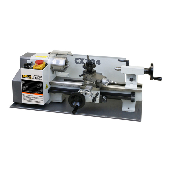
MODEL CX704 – 7” x 12” MINI METAL LATHE As part of the growing line of Craftex metalworking equipment, we are proud to offer the CX704 a 7” x 12” Mini Metal Lathe. By following the instructions and procedures laid out in this user manual, you will receive years of excellent service and satisfaction. -
Page 6: Physical Features
CX704 - MINI METAL LATHE PHYSICAL FEATURES Variable Speed Switch Tailstock Forward/Reverse Switch Tailstock Hand Wheel Emergency Stop Button Bed Way Chuck Lead Screw Tool Post Thread Dial Compound Slide Automatic Feed Lever Compound Slide Hand Wheel Cross Slide Hand Wheel... -
Page 7: Setup
Some WARNING! of the parts come assembled with the CX704 is a heavy machine, do not over- machine because of shipping purposes. exert yourself. Use fork truck or other mechanical devices or get the help of a friend for safe moving method. -
Page 8: Proper Grounding
Improper connection of the equipment- grounding conductor can result in a risk CX704 is for use on a normal 110 volt of electric shock. Check with a qualified circuit. Make sure that the machine is electrician if you are in doubt as to connected to an outlet having the same whether the outlet is properly grounded. -
Page 9: Hand Wheel Handles
Figure-4 Installing the cross feed hand wheel handle BASIC CONTROLS Figure-2 Installing the tailstock hand wheel This section describes the basic controls of handle the CX704. Use the figure and read the descriptions understand basic controls of this lathe. Figure-3 Installing longitudinal hand wheel... -
Page 10: Test Run
Failure to do so may cause serious personal injury or damage to the lathe. TO TEST RUN THE CX704: Figure-6 Rear controls Remove all the tools and objects used for assembling the machine. -
Page 11: Chuck Jaws Replacement
TO REMOVE THE CHUCK / FACEPLATE: Replacing the chuck jaws is very simple on Make sure the cord is disconnected from CX704. You just have to pay attention to the power source. the sequence in which the jaws are loaded into the chuck. -
Page 12: Tailstock
Tap the chuck / faceplate with a rubber TAILSTOCK POSITIONING mallet (if needed) and pull it out. TO ADJUST THE LONGITUDINALLY: TO INSTALL THE CHUCK / FACEPLATE: Make sure the cord is disconnected from the power source. Remove the studs from the old faceplate / chuck you just removed and thread them Loosen the tailstock lock nut securing the into the faceplate / chuck you want to... -
Page 13: Dead Center
TOOL POST rest can be moved with its finger around the work-piece. A four-way tool post is supplied with CX704 which rotates to four 90° preset stops or at Slide the work-piece between the steady any angle in between. Cutting tools can be... -
Page 14: Cross Slide
Position the steady rest on the lathe bed CROSS SLIDE where desired and secure it in place by tightening the nut. The cross slide allows the cutting tool to travel perpendicular to the bed and features scale hand wheel having graduations of 0.001". -
Page 15: Compound Slide
MANUAL MOVEMENT COMPOUND SLIDE The manual movement of the carriage can The compound slide rotates at a set angle be controlled using the hand wheel shown and features a graduation scale of 0.001". in figure-14. TO ADJUST THE COMPOUND SLIDE: Loosen the bolts located on the compound slide shown in figure-13. -
Page 16: Changing Gears
Failure to do so could result damage to the lathe. CHANGING GEARS The gears on CX704 can be changed for a variety of different feed rates. Figure-17 Threads per inch chart Figure-16 Gears and adjuster... -
Page 17: Threads Cutting
THREADS CUTTING MAINTENANCE Several different threads can be cut using During the life of your machine, you will the proper combination of gears and need to practice some regular maintenance settings. to keep your lathe in peak performance condition. Set the compound slide to the proper angle required for the cut and align the tip of the Check your machine daily for the following cutting tool with the center of the work-... -
Page 18: Lubrication
Every day, after the operation, eliminate all GIBS ADJUSTMENT the chips and clean different parts of the machine tool and apply machine tool oil to The cross slide and the compound slide prevent from rusting. gibs will need adjusted after sometimes. -
Page 19: Motor Brushes Replacement
TO CHECK THE CENTERS ALIGNMENT: MOTOR BRUSHES REPLACEMENT Center drill a 6" piece of bar stock on one end and position it between the headstock TO REPLACE THE MOTOR BRUSHES: and tailstock as shown in figure-22. Make sure the cord is disconnected from the power source. - Page 20 Figure-24 Stock thinner at the tailstock end TO MOVE THE TAILSTOCK: Make sure the switch is in the OFF position and the cord is disconnected from the power outlet. Adjust the tailstock offset half the amount by turning the offset screw. Turn another 0.010"...
-
Page 21: Wiring Diagram
WIRING DIAGRAM FOR CX704... -
Page 23: Parts List
CX704 PARTS LIST Shifting Lever PART# DESCRIPTION Shifting Grip Bed Way Handle 3 Jaws Chuck Fanning strip Spindle Compressive Spring Screw M6 × 25 Indicator Nut M6 Pinion 25T Key M5 × 50 Support Screw Key M4 × 8 Pinion 20T Screw M5 ×... - Page 24 Slide carriage box Screw M4 × 14 Slope lock block Gib Strip Washer Small carriage Screw M4 × 8 Tool Rest fixed position Screw M6 × 25 Half nuts Tool rest handle seat Angle Block Tool Rest Screw M4×10 Stud M10 × 65 Groove plate opening Lead screw Handle seat...
- Page 25 Handle seat Small spacer Pulley Spring Motor Washer Motor Cover Screw M8*55 Power cord Guard Screw M4*38 Rear Splash Guard Nut M4 H/L Label Plate of tailstock H/L Label Screw M5*16 Warning Label Base body cover Gear Screw M5*25 Gear Chuck guard Gear Shaft...
- Page 26 Support Pin Protective Cover Washer Screw M5*20 Washer Screw M6×10 Screw M6×16 Screw M8×25 Screw M4×8 Flange Screw Screw M6×8...
-
Page 27: Warranty
This warranty shall not apply to consumable products such as blades, bits, belts, cutters, chisels, punches etceteras. Craftex shall in no event be liable for injuries, accidental or otherwise, death to persons or damage to property or for incidental contingent, special or consequential damages arising from the use of our products.
Need help?
Do you have a question about the CX704 and is the answer not in the manual?
Questions and answers