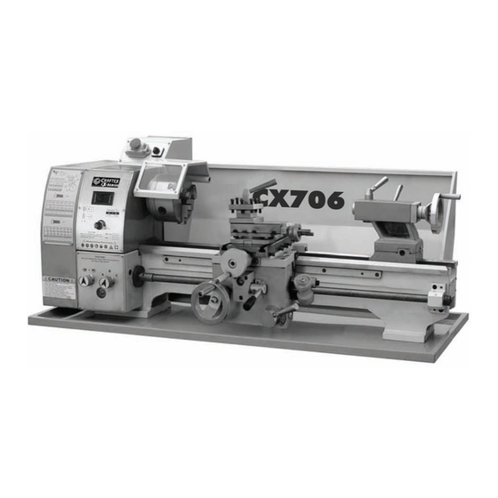
Summary of Contents for Craftex CX706
- Page 2 TABLE OF CONTENTS General Safety Instructions for Machines .................... 2 CX706 Specific Safety Instructions ...................... 3 Features............................... 4 Tool Box Contents ..........................5 Unpacking and Cleanup........................6 GENERAL DESCRIPTION ........................7 Lathe Bed............................. 7 Headstock ............................7 Gearbox ............................... 7 Carriage ...............................
- Page 3 Longitudinal Turning with Auto-Feed ....................12 Change Gears Replacement........................12 Threading and Feeding Table for Lathe....................13 Straight Turning ...........................14 Facing and Recesses ..........................14 Turning Between Centers ........................14 Taper Turning Using Tailstock Offset....................14 Taper Turning by Setting the Top Slide ....................15 Thread Cutting .............................15 LATHE ACCESSORIES ........................16 Three Jaw Universal Lathe Chuck .......................16 Four Jaw Independent Lathe Chuck ....................16...
- Page 9 are a reconfigure according to the gear chart. is eliminated by...
- Page 10 secured secured...
- Page 11 knob (C) knob (C) on the pulley.
- Page 12 Tighten the h clockwise to lock and counter-clockwise to unlock. l Handwheel Handle Move the handle up down unlock. L (not shown)
- Page 13 OPERATIONS Replacement of Chuck The head spindle holding fixture is cylindrical. Loosen three set screws and nuts (A, Fig.17, only two are shown) on the lathe chuck flange to remove the chuck. Position the new chuck and fix it using the same set screws and nuts.
- Page 14 manual feed chart Fig. 21 s as for the desired knobs change gear support change gear support change gears Fig-22 secure Secure change gear support (C, Fig 23)
- Page 15 THREADING AND FEEDING TABLE FOR LATHE 30 63 55 63 80 40 80 30 H 75 H 70 0.0025 0.0035 0.005 0.007 0.01 0.014 0.0014 0.002 0.0028 0.004 35 50 45 60 45 50 30 40 45 50 30 40 30 40 35 40 80 63...
- Page 17 w o r k - p i e c e w o r k - p i e c e...
- Page 20 How to Adjust? is adjusted...
- Page 23 MAINTENANCE Keep the maintenance of the machine tool during the operation to guarantee the accuracy and service life of the machine tool. 1. In order to retain the machine’s precision and functionality, it is essential to treat it with care, keep it clean and grease and lubricate it regularly.
- Page 24 TROUBLESHOOTING Problem Possible Reason Elimination Surface of workpiece too Tool blunt Resharpen tool rough Tool springs Clamp tool with less overhang Feed too high Reduce feed Radius at the tool tip too small Increase radius Workpiece becomes coned Centers are not aligned (tailstock has Adjust tailstock to the center offset) Top slide not aligned well (cutting with...
- Page 26 CX706 Headstock Assembly Part No. Customer's Part No. Description & Specification PCX706HS01 SPINDLE PCX706HS02 KEY M8 X 8 x 45 PCX706HS03 EXTERNAL SPACER PCX706HS04 SPINDLE BEARING 32009 PCX706HS05 INNER SPACER PCX706HS06 HEADSTOCK BODY PCX706HS07 NUT - HEX M10-1.5 PCX706HS08 STUD - M10-1.5 X 115 THREADED DOUBLE END...
- Page 28 CX706 Gearbox Assembly Part No. Customer's Part No. Description & Specification PCX706GB01 C-RING Φ14 EXTERNAL PCX706GB02 SCREW - CAP M5-0.8 X 10 PCX706GB03 LEFT FLANGE PCX706GB04 BEARING 6202 PCX706GB05 KEY M5 X 5 X 12 PCX706GB06 SHAFT WITH DOUBLE GEAR 24/24T, M=1.25...
- Page 30 CX706 Carriage Tool Post Cross Slide Assembly Part No. Customer's Part No. Description & Specification PCX706CS01 HANDLE PCX706CS02 HANDLE BASE PCX706CS03 WASHER - FLAT (SPECIAL) PCX706CS04 TOOL POST 4-WAY PCX706CS05 SCREW - SQUARE HEAD (SPECIAL) M8-1.25 X 30 PCX706CS06 PIN - (SPECIAL) PCX706CS07 NUT - HEX M4-0.7 X 16...
- Page 31 CX706 Carriage Tool Post Cross Slide Assembly Part No. Customer's Part No. Description & Specification PCX706CS49 SCREW - CAP M5-0.8 X 8 PCX706CS50 HANDLE SLEEVE PCX706CS51 HANDLE BOLT PCX706CS52 BEARING - THRUST 5101 PCX706CS53 SCREW - CAP M5-0.8 X 20...
- Page 33 CX706 Apron Assembly Part No. Customer's Part No. Description & Specification PCX706AP01 HANDLE BOLT PCX706AP02 HANDLE SLEEVE PCX706AP03 NUT - ACORN M8-1.25 GB/T889/1-2000 PCX706AP04 WASHER - FLAT M8 PCX706AP05 HANDWHEEL PCX706AP06 DIAL RING PCX706AP07 SPRING PIECE PCX706AP08 DIAL FLANGE PCX706AP09 SCREW - CAP M5-0.8 X 12...
- Page 34 CX706 Apron Assembly Part No. Customer's Part No. Description & Specification PCX706AP54 COUNTERSUNK SCREW M5-0.8 X 12-Z2 PCX706AP55 PIN - SPRING Φ5 X 40 PCX706AP56 HANDLE BASE PCX706AP57 PIN - SPRING Φ4 X 28 PCX706AP58 HANDLE BASE PCX706AP59 HANDLE PCX706AP60...
- Page 36 CX706 Tailstock Bed Assembly Part No. Customer's Part No. Description & Specification PCX706TS01 TAILSTOCK QUILL PCX706TS02 LEADSCREW NUT PCX706TS03 LEADSCREW T12 X 10 TPI PCX706TS04 KEY 4 X 4 X 15 PCX706TS05 KEY - FEATURE JY240-10-28 PCX706TS06 LOCK HANDLE SEAT...
- Page 37 CX706 Tailstock Bed Assembly Part No. Customer's Part No. Description & Specification PCX706TS54 WASHER - FLAT Φ15 PCX706TS55 NUT - HEX M12-1.25 PCX706TS56 PIN - (LOCATING) Φ6 X 25. PCX706TS57 SCREW - CAP M6-1 X 12 PCX706TS58 KEY - FLAT 5 X 5 X 25 PCX706TS59 PIN - TAPER Φ3 X 22 (BRASS )
- Page 38 CX706 Electrical Box Assembly...
- Page 39 CX706 Electrical Box Assembly Part No. Customer's Part No. Description & Specification PCX706EB01 KNOB - SPEED CONTROL PCX706EB02 SCREW - CAP M3-0.5 X 6 PCX706EB03 NUT - HEX M4-0.7 PCX706EB04 LABEL PCX706EB05 SWITCH - FOR / REV ZH-A PCX706EB06 SPEED DISPLAY PCX706EB07 SCREW M4-0.7 X 14...
- Page 41 CX706 Quadrant Assembly Part No. Customer's Part No. Description & Specification PCX706QA01 OIL CUP Φ6 PCX706QA02 NUT - HEX M12-1.25 PCX706QA03 SHAFT PCX706QA04 WASHER - SPECIAL PCX706QA05 BUSHING PCX706QA06 CHANGE GEAR 30T PCX706QA07 CHANGE GEAR 63T PCX706QA08 WASHER - FLAT SPECIAL...


Need help?
Do you have a question about the CX706 and is the answer not in the manual?
Questions and answers