Advertisement
Quick Links
Advertisement

Related Manuals for Craftex CX708


Summary of Contents for Craftex CX708
- Page 2 CX708 - 10” × 18” METAL LATHE INDEX General Safety Instruction Page 3 Features & Specifications Page 4 Installation & Lifting & Operation Page 5 - 9 Maintenance and Lubrication Page 10 - 12 Transmission System of Lathe Page 13 Parts Listing –...
-
Page 3: General Safety Instruction
GENERAL SAFETY INSTRUCTIONS EXTREME CAUTION SHOULD BE USED IN OPERATING ALL POWER TOOLS KNOW YOUR POWER TOOL, BE FAMILIAR WITH ITS OPERATION. READ THE OWNER’S MANUAL AND PRACTICE SAFE USAGE PROCEDURES AT ALL TIMES. □ CONNECT your machine ONLY to the matched and specified power source. □... -
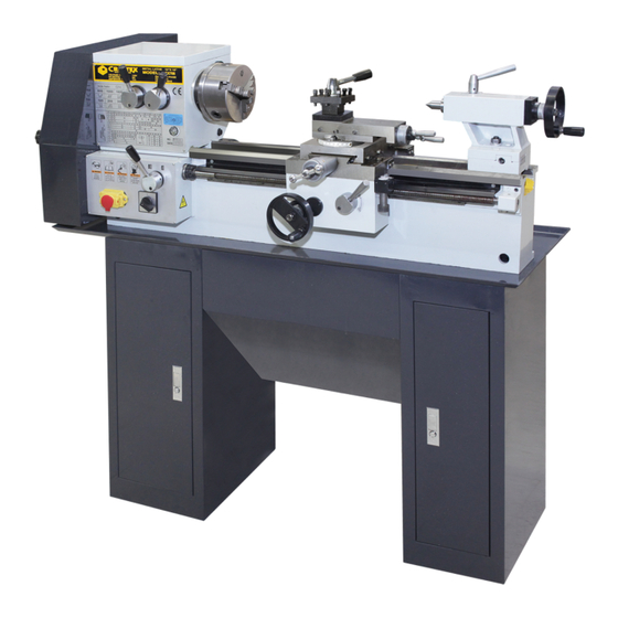
Page 4: Features & Specifications
CX708 - 10″× 18″ METAL LATHE As part of the growing line of Craftex metalworking equipment, we are proud to offer the B2227L Metal Lathe. The Craftex name guarantees Craft Excellence. By following the instructions and procedures laid out in this owner’s manual, you will receive years of excellent service and satisfaction. -
Page 5: Installation & Lifting & Operation
Installation & Lifting & Operation 1. Carefully open the crate and check for any damage to the lathe before you go any further. Make sure all standard accessories are accompanied with your lathe. 2. When lifting the lathe from the crate be sure to watch out for the center of gravity, to avoid any accidents. - Page 6 Installation Continued After calibrating the mounting level of the lathe you should fill the spindle box with No. 10 to No.20 machine oil. The oil level indicator on the front end of the headstock. At this time you should also fill up the oil filler points at the different areas of the lathe with lubrication oil.
- Page 7 Feed Box Continued Fig. # 2 Handle Position for control spindle rotating speed Fig. # 3 Diagram Sketch of gear transmission For Threading this machine can be set up in a 3 or 4 gear combination. By removing or installing the spacers (D, C) Fig 4 provided on the main drive shaft and the intermediate drive shaft.
- Page 8 Table 1 Change Gear needed for Different Feed, & Threading Pitch and the Change Gear System Apron Set the handle (4) Fig. 1 to the open position and turn the hand wheel (3). You can make manual longitudinal movement of the apron and the machine saddle. You must set the switch lever (4) Fig.1 to the close position so that you can maneuver Longitudinal feed and the threading.
- Page 9 Tail stock The hex nut (5) Fig. 1 is used to clamp the tailstock onto the machine bed. To loosen the tailstock sleeve loosen handle (7) then you can turn the hand wheel (6) so the sleeve can telescopically move forward and backward. Each scale on the dial indicator is for 0.05mm. Once the tail stock sleeve is at the desired position you must remember to tighten handle (7) again.
-
Page 10: Maintenance And Lubrication
MAINTENANCE AND LUBRICATION You must always maintain your Craftex CX708 Lathe to ensure a high working accuracy and long life. ten days after the machine is put into normal use, it is necessary to change the oil in the headstock. Remove the oil drain plug under the front side of the headstock. At this time it be a good idea to clean any shavings and or residue out of the headstock. - Page 11 Table 2 Description of Gear, Screw, Nut Used in All Parts of the Machine TABLE 2 Module screw Angle of Ser No No of tooth pitch ceffident Press Material Part Item in Fig No of helix of change Angle of Remarks positiion screw...
- Page 12 Continued Table #2 Module screw Angle of Ser No No of tooth pitch ceffident Press Material Part Item in Fig No of helix of change Angle of Remarks positiion screw Gear 20° Gear shaft 20° Gear rack 20° Leadscrew 30° 30°...
- Page 13 Transmission system of the B2227LN Lathe...
- Page 14 BED & CARRIAGE PARTS FOR B2227LN Ser No. Name Qty. Bearing Setting Screw Handle Bush Handle Knob Round Nut Dial Ring Spring Sheet Dial Lead-Screw Support Bolt Oil Cup Scale Screw Lead-Screw Flat Kay Screw Clamping Plate Screw Round Pin Screw for T Slot Screw Chip Pan...
- Page 15 Screw Rack Bar BED AND CARRIAGE DIAGRAM...
- Page 16 APRON PARTS FOR B2227LN Ser No. Name Qty. Washer Washer Transmit Shaft Shaft Bush Idler Shaft Change Gear Support Key-Nut Rotating Shaft Change Gear Taper Pin Star-Style Knob Washer Shaft Bush Taper Pin Door Knob Adjusting Washer V Shaft Screw Bolt Washer Washer Box Door...
- Page 17 Change Gear Box Cover Flat Key Electric Motor (Single Phase) APRON DIAGRAM...
- Page 18 FEEDING BOX PARTS FOR CX708 Ser No. Name Qty. Transmit Shaft Screw Bush Baffle Baffle Clutch Connecting Bush Bearing Feeding Box Oil Cup Screw Bush Thrust Ring Round Nut Lead-screw Oil cap Supporting Set Bush Steady Plate Dial Screw Clutch...
- Page 19 Steel ball Bush FEEDING BOX DIAGRAM...
- Page 20 HEAD-STOCK PARTS FOR CX708 Ser No. Name Qty. Screw Left Cover for Shaft Bearing Washer Ring Washer Ring shaft Blockage Triple Gear Blockage Screw Screw Head- Stock Head- Stock Cover Bearing Screw Right cover for 1 shaft Washer Ring Gear...
- Page 21 Gear- Shaft for Spindle Gear HEAD-STOCK PARTS FOR CX708 Ser No. Name Qty. Washer Screw Bolt Gear Gear Washer Bearing 32009 Oil Scraper Ring Front Cover Spindle Shaft Screw Bush Gear Baffle Bush Baffle Knob Handle Rod Screw Flange Yoke Shaft...
- Page 22 HEAD-STOCK DIAGRAM...
- Page 23 COMPOUND SLIDE PARTS FOR B2227LN Ser No. Name Qty. Braking Block Screw T- slot Nut Knocking Pin Screw Sliding Base T- screw Cap Shaft Long Handle Sleeve Handle Rod Handle Base Washer Slide Spring Oil Cap Sliding Carriage Sliding Nut Lead Screw Supporter Dial...
- Page 24 COMPOUND SLIDE DIAGRAM...
- Page 25 CHANGE GEAR BOX PARTS FOR CX708 Ser No. Name Qty. Washer Washer Transmit Shaft Shaft Bush 1 Dler Shaft Change-Gear Support Key – Nut Rotating Shaft Change Gear Allen Bolt Adjusting Washer V shaft Screw Bolt Washer Washer Box Door “O”...
- Page 26 CHANGE GEAR BOX DIAGRAM...
- Page 27 TAILSTOCK PARTS FOR PARTS FOR CX708 Index No. Description Qty. Sleeve Key-Nut Screw Washer Screw Handle Set Handle Shaft Handle Bush Oil Cup Tail Block Screw Tail Lead-screw Bush Flange Screw Dial Wheel Handle Taper Pin Screw Tailstock Carriage Clamp Plate...
- Page 28 TAIL-STOCK DIAGRAM...
-
Page 29: Trouble Shooting
Trouble Shooting Trouble Probable Cause Remedy Defective ON / OFF switch Replace defective parts or damaged power cord. Motor will not run Have a qualified technician Burned out motor replace the motor Lathe slows down while V - belt loose Adjust tension turning Tailstock rocks back and...
Need help?
Do you have a question about the CX708 and is the answer not in the manual?
Questions and answers