Table of Contents
Advertisement
Advertisement
Table of Contents

Subscribe to Our Youtube Channel
Related Manuals for Black Box ServSwitch ACU5010A


Summary of Contents for Black Box ServSwitch ACU5010A
- Page 1 SEPTEMBER 2002 ACU5010A ACU5011A...
- Page 2 No matter how large or small your setup is, no matter how simple or how complex, we’re confident we have a ServSwitch system that’s just right for you. The ServSwitch™ family from Black Box—the one-stop answer for all your video and KVM switching and extension needs! This manual will tell you all about your new ServSwitch™...
- Page 3 SERVSWITCH™ WIZARD EXTENDER FEDERAL COMMUNICATIONS COMMISSION AND INDUSTRY CANADA RADIO-FREQUENCY INTERFERENCE STATEMENTS This equipment generates, uses, and can radiate radio-frequency energy, and if not installed and used properly, that is, in strict accordance with the manufacturer’s instructions, may cause interference to radio communication. It has been tested and found to comply with the limits for a Class A computing device in accordance with the specifications in Subpart B of Part 15 of FCC rules, which are designed to provide reasonable protection against such interference when the equipment is...
- Page 4 EU DECLARATION OF CONFORMITY EUROPEAN UNION DECLARATION OF CONFORMITY This equipment has been tested and found to comply with the limits for a class A computing device in accordance with the specifications in the European standard EN55022. These limits are designed to provide reasonable protection against harmful interference.
- Page 5 SERVSWITCH™ WIZARD EXTENDER NORMAS OFICIALES MEXICANAS (NOM) ELECTRICAL SAFETY STATEMENT INSTRUCCIONES DE SEGURIDAD 1. Todas las instrucciones de seguridad y operación deberán ser leídas antes de que el aparato eléctrico sea operado. 2. Las instrucciones de seguridad y operación deberán ser guardadas para referencia futura.
- Page 6 NOM STATEMENT 12. Precaución debe ser tomada de tal manera que la tierra fisica y la polarización del equipo no sea eliminada. 13. Los cables de la fuente de poder deben ser guiados de tal manera que no sean pisados ni pellizcados por objetos colocados sobre o contra ellos, poniendo particular atención a los contactos y receptáculos donde salen del aparato.
-
Page 7: Table Of Contents
3.1 What You Will Need ................18 3.2 Placement ..................20 3.3 The Installation Procedure .............. 22 4. Configuration ................... 26 4.1 Configuring an Attached PC (ACU5010A Only) ......26 4.2 Configuring the Extender ..............27 4.2.1 Setting the DIP Switches ............27 4.2.2... -
Page 8: Chapter Page
7.3 Other Problems and Possible Solutions .......... 53 7.4 Resetting the Extender (Hardware Reset) ........54 7.5 Displaying the Extender’s Firmware Revision ......... 54 7.6 Calling Black Box ................55 7.7 Shipping and Packaging ..............55 Appendix: Cable Guidelines ................56 A.1 Cabling from the Keyboard, Monitor, and Mouse to the Receiver ... -
Page 9: Specifications
Between transmitters and receivers: Up to 200 m (655 ft.) of unshielded twisted-pair cable or 100 m (325 ft.) of shielded twisted-pair cable; From ACU5010A transmitter: 5 m (15 ft.) to any attached CPU; From ACU5010A receiver or ACU5011A: 10 m (30 ft.) to any attached keyboard, monitor, or mouse;... - Page 10 5 to 60% noncondensing Tolerance — Enclosure — Steel and stainless steel Power — ACU5010A transmitter: 5 VDC at 500 mA (normally draws only 180 mA) from attached CPU’s keyboard interface; ACU5010A receiver or ACU5011A using included external power adapter:...
- Page 11 SERVSWITCH™ WIZARD EXTENDER Consumption: Power (cont’d) — ACU5010A transmitter: 0.9 watts typical, 2.5 watts maximum; ACU5010A receiver or ACU5011A: 2.5 watts maximum; Size — ACU5010A transmitter, ACU5010A receiver, ACU5011A: 1"H x 4.9"W x 3.1"D (2.5 x 12.5 x 7.9 cm); rear edge of endplate protrudes an additional 0.4"...
-
Page 12: Introduction
There are a number of individual products in the Wizard Extender line. Two are covered by this manual: • The ServSwitch Wizard Extender Kit (ACU5010A) includes both a transmitter and a receiver. • The ServSwitch Wizard Extender Receiver (ACU5011A) is a single receiver that can be used with the ServSwitch™... -
Page 13: Features And Benefits
SERVSWITCH™ WIZARD EXTENDER 2.1 Features and Benefits Some useful features of the Extender: • Enables a keyboard, monitor, and mouse to be located up to 200 meters (655 ft.) of UTP or 100 meters (330 ft.) of STP from a computer or KVM switch. - Page 14 CHAPTER 2: Introduction • Flash-upgradeable through its keyboard ports. • Power/activity LED indicators confirm correct operation. • Robust metal cases ensure good shielding and video quality. • Supports IBM ® PC compatibles, Compaq ® Alpha ® , SGI™, and RS/6000 ®...
-
Page 15: Complete Packages
• (1) Power adapter for the receiver, including a region-specific input cord; • (1) Pan-head screw for attaching the module to the Extender Chassis; • (4) Adhesive rubber feet; and • This manual. If you didn’t receive everything, or if anything arrived damaged, contact Black Box right away. -
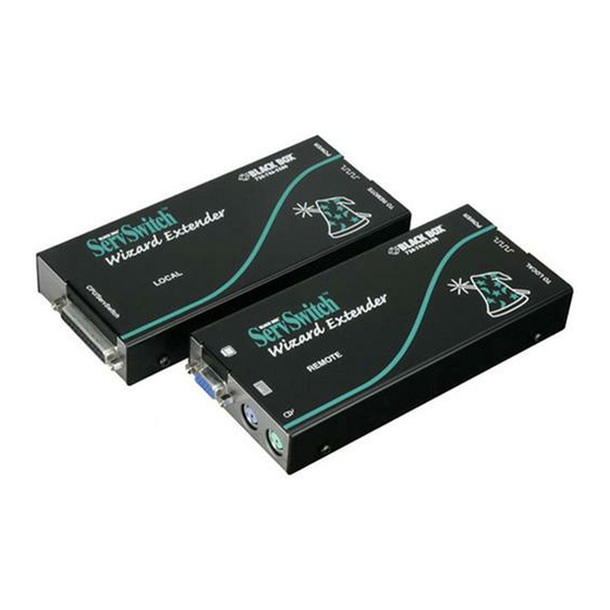
Page 16: The Extender Illustrated
CPU or KVM switch Figure 2-1. The Extender’s transmitter (local part of ACU5010A). VIEW FROM VIEW FROM RJ-45 LEFT SIDE RIGHT SIDE interconnect... - Page 17 SERVSWITCH™ WIZARD EXTENDER Slots for up to 16 transmitters, receivers, and chassis power supplies Figure 2-3. The ServSwitch Wizard Extender Chassis (ACU5000A).
-
Page 18: Safety Concerns
Extender equipment does not exceed the rated current in amperes of the cord, outlet, or circuit. • Do not attempt to service the Extender yourself. Instead, call Black Box Technical Support as described in Section 7.6. -
Page 19: Installation
SERVSWITCH™ WIZARD EXTENDER 3. Installation 3.1 What You Will Need These things must be in place before you can install your ServSwitch™ Wizard Extender: • Four-pair (eight-wire) twisted-pair cabling rated to at least Category 5. This should be long enough to reach from your Extender transmitter to the receiver, up to a maximum of 200 meters (655 feet). - Page 20 For more information about cabling, see the Appendix. For assistance figuring out which cables and adapters you’ll need, call Black Box Technical Support. • If you’ll be mounting an Extender transmitter or receiver on a wall or some other non-horizontal flat surface, you’ll need adhesive mounting strips—...
-
Page 21: Placement
SERVSWITCH™ WIZARD EXTENDER 3.2 Placement NOTE If you’d like to put an Extender module in a space in which its rackmount-enabling endplate doesn’t fit well, or if you need to remove its endplate for whatever other reason, you can do so by unscrewing the two end-mounted screws that hold it on. - Page 22 CHAPTER 3: Installation You can cover one (ACU5003) or four (ACU5004) empty slots in the chassis using our Blank Chassis Panels. The ACU5003 Single Blank Panel comes with one (ACU5003) or two screws that you’ll use to secure it to the chassis in the same way you’d secure a module.
-
Page 23: The Installation Procedure
SERVSWITCH™ WIZARD EXTENDER 3.3 The Installation Procedure First make sure the power adapter is unplugged and disconnected from the ServSwitch Wizard Extender’s receiver. Also make sure that (if possible) all of the devices you want to attach to your Extender system are turned off and unplugged. (If you have to “hot-plug”... - Page 24 AC-power outlet. The receiver (and the chassis power supply if you’re using one) should begin operating immediately; they have no on/off switch. 8A. If you’re using the full Extender kit (ACU5010A), plug in and power up the CPU or KVM switch attached to the transmitter. The transmitter should begin operating immediately;...
- Page 25 Keyboard, mouse, and monitor plug in directly or with extension cables (see the Appendix) Receiver included power adapter CAT5 or higher cable, Transmitter up to 200 m (655 ft.) Included three-to-one cable Computer CPU Figure 3-3. A simplified ACU5010A Wizard Extender installation.
- Page 26 CHAPTER 3: Installation Keyboard, mouse, Receiver and monitor plug in directly or with extension cables (see the Appendix) Remote user #1 CAT5 or higher cable, up to 200 m (655 ft.) ServSwitch Duo (KV6108SA) Optional local Local user #2 Computer CPUs connected with EHN408 cables user #1 Local users’...
-
Page 27: Configuration
4.1 Configuring an Attached PC (ACU5010A Only) If you’ve directly attached a PC to the standalone transmitter of a full ACU5010A Extender kit, configure it in the same way that you would if your keyboard, mouse, and monitor were all connected directly to it, but keep these things in mind: •... -
Page 28: Configuring The Extender
CHAPTER 4: Configuration 4.2 Configuring the Extender The ServSwitch Wizard Extender ships from the factory in a default state that’s suitable for most applications, but it has a large number of configuration options. You’ll set different options using one of two different methods: •... - Page 29 SERVSWITCH™ WIZARD EXTENDER Top of receiver Bottom of receiver Position 1 OFF: Position 4 OFF: Normal operation (default) Automatic video compensation (default) Position 4 ON: Position 2 ON: Manual video compensation Upgrade mode for receiver Positions 2 & 3 OFF: Hotkeys = [Ctrl] + [Shift] (default) Position 2 OFF, 3 ON: Hotkeys = [Alt] + [Shift]...
- Page 30 CHAPTER 4: Configuration • Position 3: If you’ve password-protected the Extender’s receiver and lost the password, move this switch position to ON to put the Extender in configuration mode when it powers up. This will allow you to reset the password, as described in Section 4.4.
-
Page 31: Using Configuration Mode
SERVSWITCH™ WIZARD EXTENDER 4.2.2 U SING ONFIGURATION If hotkeys are currently enabled (see Section 4.2.1), you can put the Extender in configuration mode by pressing the currently selected hotkeys along with the [Enter] key. For example, if the currently selected hotkey combination is the default pairing of [Ctrl] and [Shift], press [Ctrl] + [Shift] + [Enter] to activate configuration mode. - Page 32 CHAPTER 4: Configuration they’re flashing slowly (to a minimum of one cycle per second for zero distance), the Extender is compensating at a low level suitable for shorter runs of twisted-pair cable. If they’re flashing quickly (to a maximum at which the cycling can no longer be distinguished and it looks like all the LEDs are “half on”...
-
Page 33: B Issuing Other Configuration-Mode Keyboard Commands
SERVSWITCH™ WIZARD EXTENDER 4. When you find the best possible picture—and finish entering any other configuration commands (see Section 4.2.2.B)—press [Enter] to save the configuration setting and exit configuration mode. The compensation setting is saved in EEPROM, so it will persist even if the Extender is powered off. For this reason, unless you change your twisted-pair cabling, you shouldn’t need to adjust this setting again. -
Page 34: Selecting The Mouse Protocol
CHAPTER 4: Configuration [M] [6] [Enter] = Restore regular mouse [M] [7] [Enter] = Restore IntelliMouse • Set/clear password (see Section 4.4): [P] [Enter] (password) [Enter] = Sets the Extender’s password [P] [Enter] [Enter] = Clears the Extender’s password • [F] [1] [Enter] = Display firmware version (see Section 7.5) •... -
Page 35: Setting A Password For The Extender
SERVSWITCH™ WIZARD EXTENDER 4.4 Setting a Password for the Extender There are many situations where access to corporate file servers or sensitive information needs to be controlled. In such circumstances, the ServSwitch Wizard Extender’s transmitter and the attached CPU can be locked away in a secure room or cabinet and controlled from the primary control station attached to the receiver. -
Page 36: Resetting The Extender To Its Factory-Default Configuration
CHAPTER 4: Configuration If you want to remove the password after setting one, get into configuration mode, type the letter “P”, and press the [Enter] key as before, but then press [Enter] again without typing in any other characters. (If you try to lock the Extender before you’ve set a password, or after you’ve removed the password, the Extender will still blank the video, but it won’t prevent anyone from accessing the CPU.) -
Page 37: Operation
SERVSWITCH™ WIZARD EXTENDER 5. Operation This chapter explains the general operation of the ServSwitch™ Wizard Extender. We recommend that you read this chapter carefully before starting to use the Extender; also make very sure you have read the important note at the start of Chapter 4! 5.1 Power-Up Status Under normal circumstances, the ServSwitch Wizard Extender is ready for use as... -
Page 38: The Extender's Leds
AC outlet being turned OFF/not working, power supply being broken, the module’s LED being defective, or the module’s main board being defective. If you can’t determine the cause of this problem, call Black Box for technical support. -
Page 39: How The Extender Uses The Keyboard Leds
SERVSWITCH™ WIZARD EXTENDER 5.3 How the Extender Uses the Keyboard LEDs The ServSwitch Wizard Extender also uses the LEDs on the attached keyboards to indicate various conditions. It will light the Num Lock, Caps Lock, and Scroll Lock LEDs in several different ways: •... -
Page 40: Things To Keep In Mind About The Keyboards And Mice
CHAPTER 5: Operation 5.4 Things to Keep in Mind About the Keyboards and Mice PC bootup sequence: When your PC CPUs are powered on, they communicate with any attached keyboards and mice and load the setup parameters required by their particular operating systems. It is necessary for the Extender to be attached and powered on during this sequence so that it can give the CPUs the required responses and keep track of all the modes and settings requested by each of the connected CPUs. -
Page 41: Keyboard Control: Hotkey Commands
SERVSWITCH™ WIZARD EXTENDER 5.5 Keyboard Control: Hotkey Commands You can control several functions on the ServSwitch Wizard Extender—including CPU connection/disconnection, screen blanking, locking, and entering configuration mode—from the keyboard, using commands triggered with the Extender’s currently selected hotkey combination. All of the hotkey-control commands are invoked by holding down the two hotkeys and then pressing a command key. - Page 42 CHAPTER 5: Operation Extender is locked, you will have to press [Enter] to clear those characters so that they won’t invalidate the password when you proceed to type it in. • Use {Hotkeys} + [Enter] to cause the Extender to go into configuration mode. See Section 4.2.2.
-
Page 43: Hot-Plugging Ps/2 Mice And Mouse Ports Into The Extender And Re-Enabling Disconnected Cpu Ps/2 Mouse Ports
SERVSWITCH™ WIZARD EXTENDER 5.6 Hot-Plugging PS/2 Mice and Mouse Ports into the Extender and Re-Enabling Disconnected CPU PS/2 Mouse Ports It is advisable to switch off the computer systems that are going to be connected to the ServSwitch Wizard Extender before you install them. However, even if this is not possible, most systems can be “hot-plugged”... - Page 44 CHAPTER 5: Operation To restore lost mouse movement on a CPU connected to the Extender: 1. At the receiver’s keyboard, select the CPU that has lost its mouse movement. 2. Enter configuration mode (see Section 4.2.2) by pressing the hotkeys followed by [Enter].
-
Page 45: Upgrading The Extender's Firmware
To upgrade the Extender’s firmware, take these steps: 1. Create an MS-DOS boot disk using a blank floppy disk. 2. Download the latest firmware upgrade files as directed by Black Box Technical Support. The firmware upgrade is available as a compressed ZIP archive containing the following files (“xxx”... - Page 46 CHAPTER 6: Upgrading the Extender’s Firmware 3. Power down the computer that will be running the upgrade program. 4. Disconnect the twisted-pair cable and any previously connected CPU from the transmitter. 5. Connect the transmitter to the computer that will be running the upgrade program as shown in Figure 6-1.
- Page 47 SERVSWITCH™ WIZARD EXTENDER 11. Power down the Extender’s receiver and disconnect the twisted-pair cable and any previously connected keyboard from it. 12. Use standard PS/2 extension cable such as product code EVNPS03 to connect the receiver’s keyboard port to the keyboard port of the computer that will be running the upgrade program, as shown in Figure 6-2.
- Page 48 CHAPTER 6: Upgrading the Extender’s Firmware 18. Reconnect the upgraded transmitter and receiver to each other and to any previously connected equipment.
-
Page 49: Troubleshooting
Extender itself as described in Section 7.4. If nothing helps, get the Extender’s firmware-revision level as described in Section 7.5 if possible, then call Black Box Technical Support as directed in Section 7.6. If you need to ship your Extender, see Section 7.7. -
Page 50: Reporting And Compensating For Video Skew
CHAPTER 7: Troubleshooting 7.2 Reporting and Compensating for Video Skew If you notice that one or more of the primary colors (red, green, or blue) in the video image displayed on your monitor has separated from the others and is horizontally offset from them on your screen—for example, if colored shadows trail bright white objects, as shown in Figure 7-1—then your Extender system might be affected by video “skew.”... - Page 51 SERVSWITCH™ WIZARD EXTENDER • If none of the other solutions are practical or if none of them work, you can install a ServSwitch™ Wizard Skew Compensator (product code ACU5100A) between your transmitter and receiver, as shown in Figure 7-2. Receiver included power adapter...
- Page 52 CHAPTER 7: Troubleshooting Before you install or configure a Skew Compensator—or try the other remedies— you might want to have the Extender report how much skew is occurring in your system. To do this, take these steps: 1. Make sure the transmitter and receiver are connected with the twisted-pair cable you want to use.
- Page 53 SERVSWITCH™ WIZARD EXTENDER The first section of the report indicates the length differences between the twisted pairs that are carrying the red, green, and blue color signals. One of the colors will have a reported length difference of “+0.0M”; this is the color carried by the shortest twisted pair.
-
Page 54: Other Problems And Possible Solutions
CHAPTER 7: Troubleshooting 7.3 Other Problems and Possible Solutions Problem: Poor video quality with smearing, fuzziness, or rippling. Possible Solution: Make sure that the video compensation has been set for your system, as described in Sections 4.2.1 and 4.2.2.A. Check for video skew; see Section 7.2. Make sure your Category 5 cable is pinned and paired properly;... -
Page 55: Resetting The Extender (Hardware Reset)
SERVSWITCH™ WIZARD EXTENDER Problem: Compaq MX11800 model integrated keyboard and mouse only: The mouse consistently fails to boot when the Extender is connected to a PC running Windows NT ® through its PS/2 style mouse port. Possible Solutions: There are three possible solutions to this problem: 1. -
Page 56: Calling Black Box
If you need to transport or ship your ServSwitch Wizard Extender: • Package it carefully. We recommend that you use the original container. • Before you ship it back to Black Box for repair or return, contact us to get a Return Authorization (RA) number. -
Page 57: Appendix: Cable Guidelines
ServSwitch Wizard Extender’s receiver. If you use a PC/AT style keyboard you’ll need a PC/AT (5-pin DIN female) to PS/2 (6-pin mini-DIN male) adapter. (These are available from Black Box as product code FA211.) You can use Premium KVM User Cables (product code EHN409) to increase the distance from the Wizard to your peripherals to as much as 32 ft. - Page 58 APPENDIX: Cable Guidelines 6-pin mini-DIN attaches to DB9 attaches to PC’s serial port or Wizard or cable from Wizard cable to PC’s serial port RLSD (DCD) KDAT TD (-12V) SGND SGND KCLK -12V Male Male Female Female Figure A-1. The RS-232 mouse adapter’s pinout.
-
Page 59: Twisted-Pair Cabling Between The Transmitter And Receiver
SERVSWITCH™ WIZARD EXTENDER A.3 Twisted-Pair Cabling Between the Transmitter and Receiver To interconnect the transmitter and receiver of your ServSwitch™ Wizard Extender, you can use either shielded twisted pair (STP) or unshielded twisted pair (UTP) rated to Category 5 or higher. It should be pinned straight-through and paired according to the TIA-568A or (preferred) -568B specification, as shown in Figure A-2. - Page 60 APPENDIX: Cable Guidelines 1 2 3 4 5 6 7 8 Cable Pinning: Straight-through (Pin 1 to Pin 1, 2 to 2, etc.) Cable Pairing: Pair 1: Pins 4 and 5 (differential green video and vertical sync) Pair 2: Pins 1 and 2 (differential blue video) Pair 3: Pins 3 and 6 (differential red video and horizontal sync) Pair 4:...
- Page 61 TRADEMARKS USED IN THIS MANUAL BLACK BOX and the logo are registered trademarks, and ServSwitch and ServSwitch Wizard are trademarks, of Black Box Corporation. Apple and Macintosh are registered trademarks of Apple Computer, Inc. Compaq and Alpha are registered trademarks of Compaq Computer Corporation.
- Page 62 NOTES...
- Page 63 NOTES...
- Page 64 Customer Support Information: FREE tech support 24 hours a day, 7 days a week: Call 724-746-5500 or fax 724-746-0746. Mailing address: Black Box Corporation, 1000 Park Dr., Lawrence, PA 15055-1018 World-Wide Web: www.blackbox.com • E-mail: info@blackbox.com © Copyright 2001. Black Box Corporation. All rights reserved.
Need help?
Do you have a question about the ServSwitch ACU5010A and is the answer not in the manual?
Questions and answers