Table of Contents
Advertisement
Quick Links
®
®
NETWORK SERVICES
FEBRUARY 2006
ACU50XXA
Wizard
Multimedia Extenders
™
USER GUIDE
Order toll-free in the U.S.: Call 877-877-BBOX (outside U.S. call 724-746-5500)
CUSTOMER
FREE technical support 24 hours a day, 7 days a week: Call 724-746-5500 or fax 724-746-0746
SUPPORT
Mailing address: Black Box Corporation, 1000 Park Drive, Lawrence, PA 15055-1018
INFORMATION
Web site: www.blackbox.com • E-mail: info@blackbox.com
Advertisement
Table of Contents

Related Manuals for Black Box Wizard ACU50 A Series


Summary of Contents for Black Box Wizard ACU50 A Series
- Page 1 Order toll-free in the U.S.: Call 877-877-BBOX (outside U.S. call 724-746-5500) CUSTOMER FREE technical support 24 hours a day, 7 days a week: Call 724-746-5500 or fax 724-746-0746 SUPPORT Mailing address: Black Box Corporation, 1000 Park Drive, Lawrence, PA 15055-1018 INFORMATION Web site: www.blackbox.com • E-mail: info@blackbox.com...
-
Page 2: Table Of Contents
Contents ® Welcome Operation Introduction .................2 Indicators ...................17 Standard Wizard AVU models..........2 Adjustments ................17 Further expansion..............3 Brightness and sharpness adjustments ........17 Transmitter cascading ............3 Skew compensation adjustments (AVU5111A only)...18 Module mixing................3 Further information Receiver cascading .............3 What’s in the box ................4 Troubleshooting ................20 What you may additionally need ..........4 Getting assistance..............20... -
Page 3: Introduction
Welcome ® Introduction Wizard AVU5004A and AVU5111A The Wizard AVU range of multimedia extenders are designed and built The Wizard AVU5004A transmitter and multiple AVU5111A modules are specifically for use wherever high quality video and sound must be faithfully designed to provide potentially enormous expansion possibilities from the reproduced at distant locations. -
Page 4: Further Expansion
Further expansion ® Transmitter cascading Receiver cascading This method of expansion is limited As mentioned earlier, the AVU5001A and AVU5004A transmitters to the AVU5111A receivers as are both capable of supporting only they are equipped with the necessary cascade port. additional transmitter modules (and LINK OUT Using the... -
Page 5: What's In The Box
What’s in the box What you may additionally need ® Video cable to connect a transmitter to the source PC and optionally to connect additional transmitter modules in cascade. * The Wizard AV5001A and Wizard Wizard AVU5011A are packaged AV5001A AVU5011A as a transmitter and receiver pair transmitter*... -
Page 6: Module Features
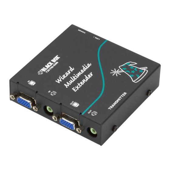
Module features ® Audio output to speakers Power supply connection Link output to receiver 1 Video output to display Receiver module Transmitter module Link outputs to (AVU5004A model pictured) (AVU5111A model pictured) Audio output to speakers receivers 2, 3 & 4 (AVU5004A only) Video output Indicators... -
Page 7: Installation
Installation ® Locations Please consider the following important points when planning the positions of your Wizard modules: • Take care not to exceed the maximum link cable lengths (please refer to the section Making cascade connections). • Ensure that the transmitters are as close as possible to the source PC system and the receivers are similarly close to the display modules. -
Page 8: Mounting
Mounting ® Before you begin connecting to the source PC system and display devices, it is advisable to mount the Wizard modules in place. There are a number of mounting possibilities for the transmitter and receiver modules: • On a horizontal surface using the supplied self adhesive feet, •... -
Page 9: Using The Optional Rack Mount Chassis
Using the optional rack mount chassis ® 1 Place the supplied rack plate onto the front of the transmitter or receiver module and secure it with the countersunk screws. 2 Orient the module on its side so that its labelled face is the correct way up and the securing plate is facing away from the rack. -
Page 10: Making Standard Connections
Making standard connections ® Connections to the Wizard modules do not need to follow the precise order given in this user guide although it is recommended that you do not apply power to the modules until all other connections have been made. Note: Unless stated otherwise, all connection information given here applies to all modules in the Wizard AVU family. - Page 11 To connect the link cable(s) ® The links between the transmitter and receiver modules are made using between one and four twisted pair cables, specified to Category 5 or higher. Each cable carries video and audio signals to each receiver module. When a single receiver is attached to a link cable, the maximum length of that link cable is 300m (1000 feet).
- Page 12 To connect the power supply ® NOTE: Please read and adhere to the electrical safety information given within Safety information section of this guide. In particular, do not use an unearthed power socket or extension cord. 1 Attach the output connector of the power supply to the socket labelled on the Wizard transmitter.
-
Page 13: Connections At The Receiver
Connections at the receiver ® To connect displays and speakers Link in Dual video and audio outputs are provided on the Wizard receiver. Both sets of The link from the transmitter to each receiver module is made using a twisted ports provide identical signals and their connection procedures are the same: pair cable, specified to Category 5 or higher. - Page 14 To connect the power supply ® NOTE: Please read and adhere to the electrical safety information given within Safety information section of this guide. In particular, do not use an unearthed power socket or extension cord. 1 Attach the output connector of the power supply to the socket labelled on the Wizard receiver.
-
Page 15: Making Cascade Connections
Making cascade connections ® Cascade connection examples The Wizard AVU series of products have been specifically designed to be flexible These examples demonstrate valid configurations and the effect of cascade in order to support both your immediate and future needs for media streaming. connections upon overall link lengths: In addition to the standard connections made from transmitters to receivers, you can also link extra transmitters to transmitters and/or receivers to receivers... -
Page 16: Cascading Transmitters
Cascading transmitters ® Expansion at the transmitter end is achieved using the video and audio output ports. The signals from these ports are connected to the video and audio inputs of the Primary transmitter next transmitter and so on. Wizard AVU5001A and AVU5004A transmitters can be mixed in a cascade in any order using the... -
Page 17: Cascading Receivers (Wizard Avu5111A Only)
Cascading receivers (Wizard AVU5111A only) ® Expansion at the receiver end is made possible using ports present on Wizard AVU5111A LINK OUT receivers. Receiver cascade links are made using twisted pair cables, specified to Category 5 or higher. NOTE: Ensure that there are no more than three cascades (transmitter or receiver cascades) between the primary transmitter and the furthest receiver in any branch. -
Page 18: Operation
Operation ® Brightness and sharpness adjustments In operation, the Wizard modules are designed to be completely transparent The brightness and sharpness adjustments - high quality video and audio from the source PC system are played as normal, provided on every Wizard receiver allow you the only difference is that they are now being seen and heard up to 1000 feet to compensate for any losses incurred within away. -
Page 19: Skew Compensation Adjustments (Avu5111A Only)
Skew compensation adjustments (AVU5111A only) ® To create a skew test pattern The twisted pair cabling used to link 1 Run any image creation/editing application, such as the Paint program 1 2 3 4 5 6 7 8 the Wizard modules consists of four supplied with Windows. - Page 20 To zero the skew adjustment dials To adjust the skew compensation ® When supplied, the two skew dials are set in Your chances of achieving a successful skew compensation adjustment will be their neutral positions. i.e. no delay to either improved if you do the following: of its colors.
-
Page 21: Further Information
Further information ® Troubleshooting If you experience problems when installing or using the Wizard modules, Power is applied via the power supply but the module operation has please check through this section for a possible solution. If your problem is not stopped. -
Page 22: Safety Information
Safety information Products in the Wizard AVU range ® • For use in dry, oil free indoor environments only. The following items are available within the Wizard AVU product range: • Do not use to link between buildings. • Wizard AVU5010A (part number: BB AVU5010A) •... -
Page 23: Emissions And Immunity
Emissions and Immunity ® A Category 5 (or better) twisted pair cable must be used to connect the modules in order to maintain compliance with radio frequency energy emission regulations and ensure a suitably high level of immunity to electromagnetic disturbances. -
Page 24: Normas Oficiales Mexicanas (Nom) Statement
Normas Oficiales Mexicanas (NOM) electrical ® safety statement Instrucciones de seguridad 15 En caso de existir, una antena externa deberá ser localizada lejos de las 1 Todas las instrucciones de seguridad y operación deberán ser leídas antes de lineas de energia. que el aparato eléctrico sea operado. - Page 25 ® © 2006 Black Box Corporation All trademarks are acknowledged. Black Box Corporation, 1000 Park Drive, Lawrence, PA 15055-1018, United States of America Tel: +1-724-746-5500 Fax: +1-724-746-0746 Documentation by: www.ctxd.com...
-
Page 26: Blackbox Subsidiary Contact Details
BlackBox subsidiary contact details ® Country Web Site/Email Phone United States www.blackbox.com 724-746-5500 724-746-0746 Austria www.black-box.at +43 1 256 98 56 +43 1 256 98 56 support@black-box.at Belgium www.blackbox.be +32 2 725 85 50 +32 2 725 92 12 support.nederlands@blackbox.be support.french@blackbox.be support.english@blackbox.be Denmark...
Need help?
Do you have a question about the Wizard ACU50 A Series and is the answer not in the manual?
Questions and answers