Table of Contents
Advertisement
®
NETWORK SERVICES
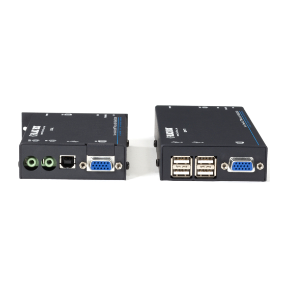
ServSwitch Wizard VGA/USB
Extend one or two* VGA video links plus four USB
devices and speakers up to nearly 1000 feet from
your computer.
Uses one or two* length of Category 5, 5e, 6, 7 or 7a twisted-pair cable.
* Dual-variant models
Order toll-free in the U.S.: Call 877-877-BBOX (outside U.S. call 724-746-5500)
Customer
FREE technical support 24 hours a day, 7 days a week: Call 724-746-5500 or fax 724-746-0746
Support
Mailing address: Black Box Corporation, 1000 Park Drive, Lawrence, PA 15055-1018
Information
Web site: www.blackbox.com • E-mail: info@ blackbox.com
®
™
ACU5050A-R2
ACU5250A-R2
Advertisement
Table of Contents

Related Manuals for Black Box ServSwitch Wizard ACU5050A-R2


Summary of Contents for Black Box ServSwitch Wizard ACU5050A-R2
- Page 1 Order toll-free in the U.S.: Call 877-877-BBOX (outside U.S. call 724-746-5500) Customer FREE technical support 24 hours a day, 7 days a week: Call 724-746-5500 or fax 724-746-0746 Support Mailing address: Black Box Corporation, 1000 Park Drive, Lawrence, PA 15055-1018 Information Web site: www.blackbox.com • E-mail: info@ blackbox.com...
- Page 2 ServSwitch Wizard VGA/USB Trademarks Used in this Manual Black Box and the Double Diamond logo are registered trademarks, and ServSwitch is a trademark, of BB Technologies, Inc. Mac is a registered trademark of Apple Computer, Inc. Linux is registered trademark of Linus Torvalds.
- Page 3 FCC and IC RFI Statements Federal Communications Commission and Industry Canada Radio Frequency Interference Statements This equipment generates, uses, and can radiate radio-frequency energy, and if not installed and used properly, that is, in strict accordance with the manufacturer’s instructions, may cause inter ference to radio communication. It has been tested and found to comply with the limits for a Class A computing device in accordance with the specifications in Subpart B of Part 15 of FCC rules, which are designed to provide reasonable protection against such interference when the equipment is operated in a commercial environment.
- Page 4 ServSwitch Wizard VGA/USB Instrucciones de Seguridad (Normas Oficiales Mexicanas Electrical Safety Statement) 1. Todas las instrucciones de seguridad y operación deberán ser leídas antes de que el aparato eléctrico sea operado. 2. Las instrucciones de seguridad y operación deberán ser guardadas para referencia futura. 3.
-
Page 5: Table Of Contents
Table of Contents Contents 1. Specifications ....................................6 2. Overview ....................................7 3. Installation ....................................8 3.1 Mounting the modules – desk or rack..........................8 3.1.1 Desk mount ................................8 3.1.2 Rack mount ................................9 3.2 Connections ................................... 10 3.2.1 Connections at the local module ........................10 3.2.2 Connections at the remote module ........................ -
Page 6: Specifications
ServSwitch Wizard VGA/USB 1. Specifications ServSwitch Wizard VGA/USB single-variant Casings (w x h x d): 118.4mm (4.66”) x 26mm (1.02”) x 74.8mm (2.94”) Construction: 1U compact case, robust metal design Weight: 0.33kg (0.72lbs) Mount kits: Rack mount Power to adapter: 100-240VAC 50/60Hz, 0.5A, Power to remote unit: 5VDC 12.5W... -
Page 7: Overview
Chapter 2: Overview 2. Overview Thank you for choosing the ServSwitch Wizard VGA-USB extenders which provide a very effective way to put distance between your computer and its peripherals. The compact casings and ease of use of the modules belie the ingenuity of their operation. Using our proprietary transmission techniques we are able to reliably transfer more signals than ever before along a single length of Category 5, 5e, 6, 7 or 7a twist- ed pair cabling. -
Page 8: Installation
ServSwitch Wizard VGA/USB 3. Installation 3.1 Mounting the modules – desk or rack The modules can be situated on a desk or alternatively, for larger installations, mounted within an optional rack mount chassis. 3.1.1 Desk mount Apply the supplied self-adhesive rubber feet to the underside of the module as shown in Figure 3-1: Figure 3-1. -
Page 9: Rack Mount
Chapter 3: Installation 3.1.2 Rack mount Note: The module switches are not accessible once it is inserted into the rack, therefore, check all settings before insertion. 1 Place the rack securing plate (available as a separate kit) onto the front of the module and secure it with the two countersunk screws. -
Page 10: Connections
ServSwitch Wizard VGA/USB 3.2 Connections Installation of the modules is straightforward and requires minimal configuration in most cases. • Connections at the local module • Connections at the remote module IMPORTANT: The ServSwitch Wizard VGA-USB can be used with other hubs in the system, but please note that the local unit should not be connected to the downstream port of a bus-powered hub due to power constraints. - Page 11 Chapter 3: Installation 3 Optionally connect a local video display to the video out feed-through connector on the local module as shown in Figure 3-5: Figure 3-5. Optionally attaching a video display to the local module [Dual-variant only] Optionally connect a second local video display to the upper socket on the local module.
- Page 12 ServSwitch Wizard VGA/USB 3.2.1.2 USB connections IMPORTANT: The Wizard VGA/USB can be used with other USB hubs in the system, but please note that due to power con- straints, the local unit should not be connected to the downstream port of a bus-powered USB hub. Additionally, Wizard VGA/ USB dual-variant local units must always be powered using their supplied power adapter.
- Page 13 Chapter 3: Installation 3.2.1.3 Audio connections 1 Optionally connect an audio link from the computer’s speaker port to the audio input port on the local module as shown in Figure 3-8. Figure 3-8. Attaching an audio input to the single- and dual-variant local modules 2 Optionally connect local speakers to the audio output port on the local module as shown in Figure 3-9.
- Page 14 ServSwitch Wizard VGA/USB 3.2.1.4 Link connections 1 Connect the link cable (up to 984 feet/300 meters in length) to the local module socket labeled as shown in Figure TO REMOTE 3-10: Figure 3-10. Attaching the CATx link cable [Dual-variant only] Attach a second category 5e, 6 or 7a link cable (up to 984 feet/300 meters in length) to the upper socket on the dual-variant local module.
- Page 15 • The single-variant local module is designed to derive its power from the host computer via the USB connection. If this is not possible, then use an optional power adapter, available from your Black Box stockist. • The dual-variant local module always requires the use of a power adapter and hence two power adapters are supplied with all Wizard VGA/USB dual-variant units.
-
Page 16: Connections At The Remote Module
ServSwitch Wizard VGA/USB 3.2.2 Connections at the remote module 3.2.2.1 Video connections 1 Where possible ensure that power is disconnected from the computer system to be connected. 2 Attach the lead from the video display to the video out socket on the remote module as shown in Figure 3-14: Figure 3-14. - Page 17 Chapter 3: Installation 3.2.2.2 USB connections 1 Attach the leads of up to four USB devices (two of which are usually a keyboard and mouse) to the sockets located adjacent to the video output connector as shown in Figure 3-16: Figure 3-16.
- Page 18 ServSwitch Wizard VGA/USB 3.2.2.4 Link connections 1 Attach the connector of the category 5, 5e, 6, 7 or 7a link cable (up to 984 feet/300 meters in length) to the ‘TO LOCAL’ socket on the remote module as shown in Figure 3-18: Figure 3-18.
- Page 19 Chapter 3: Installation 3.2.2.5 Remote module power 1 Attach the output connector of the power adapter to the ‘POWER’ socket of the remote module as shown in Figure 3-20: Figure 3-20. Attaching the power adapter 2 Attach the IEC power cord to the power adapter body and insert the mains plug of the cord to a nearby power outlet as shown in Figure 3-21: Figure 3-21.
-
Page 20: Dual User Configuration
ServSwitch Wizard VGA/USB 3.2.3 Dual user configuration You can combine two ServSwitch Wizard VGA-USB extender sets to create a dual user configuration. Such an installation would allow a single computer to be controlled from two different positions, with each position receiving the same audio visual output and having equal and concurrent control over the computer. - Page 21 Chapter 3: Installation First local module Video crosslink Audio, USB and from first to video from the PC second local module Audio crosslink from first to second local module Second USB from the PC Figure 3-23. Interconnections required for a dual user configuration Most of the connections are similar to the standard configuration.
-
Page 22: Video Display (Ddc) Information
ServSwitch Wizard VGA/USB 3.3 Video display (DDC) information The Display Data Channel (or DDC) is an industry standard scheme which allows video monitors to declare their capabilities to the computer’s video adapter circuitry, allowing the latter to optimise their outputs accordingly. Since the widespread adoption of the scheme, video adapters have become increasingly dependent on receiving relevant DDC information during startup, before they will output anything more than a rudimentary video signal. -
Page 23: Ddc Indications
Chapter 3: Installation 3.3.1 DDC indications When power is first applied to the local module (either from the computer’s USB port or an optional power adapter) it will search for valid DDC data on its video out connector. During this process, the green indicator (built into the link connector) will flash to indicate its progress: •... -
Page 24: Video Compensation
• Video gain - Alter the signal gain for the image. • Color skew - Adjust the timing of each color to fine tune the image. • Expert mode - Please contact Black Box technical support for details. What is skew and why is compensation needed? The twisted pair cabling supported by the ServSwitch Wizard VGA-USB modules consists of four pairs of wires per cable, three of which are used to convey red, green and blue video signals to the remote video monitor. -
Page 25: To Enter Video Compensation Mode
Chapter 3: Installation 3.4.1 To enter video compensation mode 1 Ensure that the two ServSwitch Wizard VGA-USB units are connected to the computer and powered on. A USB keyboard must be connected to the remote unit. 2 Arrange your test images on the remote screen. Please refer to the section ‘Test images while compensating’ shown bottom left. -
Page 26: To Set The Cable Type
ServSwitch Wizard VGA/USB 3.4 Video compensation (continued) Once you have entered video compensation standby level, you can choose which adjustments to make. Generally you should set the cable type and cable length options first. Then, if necessary, use the video gain and color skew adjustments to fine tune the remote video image. -
Page 27: To Adjust Video Gain
Chapter 3: Installation 3.4.5 To adjust video gain a From standby, use to decrease or increase the gain level. If necessary, press to return to a neutral setting. Gain adjustments are saved automatically. 3.4.6 To adjust color skew You will only need to use these adjustments if the video image is not sharp after adjusting the cable type and length. -
Page 28: Operation
When using two sets of ServSwitch Wizard VGA-USB modules to allow two users to access a single computer, be aware that arbi- tration between the users is handled by the USB sub-system of the computer. Unlike with other Black Box products, this means that both users can control the computer at exactly the same time and the resulting keyboard and mouse influences will be an amalgam of the two inputs - i.e. - Page 29 Chapter 4: Operation 724-746-5500 | blackbox.com Page 29...
-
Page 30: Appendix A. Troubleshooting
ServSwitch Wizard VGA/USB Appendix A. Troubleshooting A.1 Status indicators The green indicators built into the link connectors on each module provide useful feedback regarding the connection and power status: During startup (of the local module) • One very short green flash: no valid DDC information available from a locally connected video monitor, no changes made to stored DDC information. -
Page 31: Appendix B. Safety Information
Appendices Appendix B. Safety Information • For use in dry, oil free indoor environments only. • Do not use to link between buildings. • Ensure that all twisted pair interconnect cables are installed in compliance with all applicable wiring regulations. •... -
Page 32: Network Services
About Black Box Black Box Network Services is your source for an extensive range of networking and infrastructure products. You’ll find everything from cabinets and racks and power and surge protection products to media converters and Ethernet switches all supported by free, live 24/7 Tech support available in 30 seconds or less.
Need help?
Do you have a question about the ServSwitch Wizard ACU5050A-R2 and is the answer not in the manual?
Questions and answers