
Related Manuals for Black Box Balun G.703


Summary of Contents for Black Box Balun G.703
- Page 1 © Copyright 1998. Black Box Corporation. All rights reserved. 1000 Park Drive • Lawrence, PA 15055-1018 • 724-746-5500 • Fax 724-746-0746...
-
Page 2: Customer Support Information
Order toll-free in the U.S. 24 hours, 7 A.M. Monday to midnight Friday: 877-877-BBOX FREE technical support, 24 hours a day, 7 days a week: Call 724-746-5500 or fax 724-746-0746 Mail order: Black Box Corporation, 1000 Park Drive, Lawrence, PA 15055-1018 Web site: www.blackbox.com • E-mail: info@blackbox.com... -
Page 4: Trademarks Used In This Manual
CE NOTICE CE Notice The CE symbol indicates that the product is in compliance with the Electromagnetic Compatibility (EMC) directive and the Low Voltage Directive (LVD) of the Union European (EU). TRADEMARKS USED IN THIS MANUAL Any trademarks mentioned in this manual are acknowledged to be the property of the trademark owners. -
Page 5: Specifications
G.703 MODULES, MODULE PANEL, AND CHASSIS 1. Specifications Data Rate — 2.048 Mbps Transmission Line — CCITT G.703 (unstructured) Connections — 75-ohm: Dual coax BNC connectors, female (RG59 or 2002 coax); 120-ohm: Shielded RJ-45 jack Link-to-Data Isolation — 500 volts AC/DC Operating Temperature —... - Page 6 CHAPTER 2: Description 2. Description 2.1 Introduction The G.703 Balun Module Panels match multiple sets of dual 75-ohm coax connections to multiple 120-ohm twisted-pair connections. This allows carriers to provide 120-ohm G.703 service to customers retaining 75-ohm CPE hardware. It also allows carriers who have standardized on 75-ohm coax to provide 120-ohm terminations to their customers (in keeping with European ONP requirements).
- Page 7 G.703 MODULES, MODULE PANEL, AND CHASSIS 2.2 Features • Connects 75-ohm dual coax to 120-ohm twisted pair. • Bi-directional signal conversion according to CCITT G.703. • Data rates up to 2.048 Mbps. • Low-profile design. • Mounts in standard 19-inch rack. •...
- Page 8 CHAPTER 3: Configuration 3. Configuration Each G.703 Balun Module is equipped with four jumpers that you may use to configure several grounding options. This chapter shows the jumper locations and describes their functions. There are five configuration jumpers on the back of the Module’s printed circuit board.
- Page 9 G.703 MODULES, MODULE PANEL, AND CHASSIS Figure 3-1. Jumper Location. Figure 3-2 shows the orientation of the rear interface- card straps. Note that the strap can either be on posts 1 and 2, or on posts 2 and 3. Figure 3-2. Possible Positions for the Jumpers.
- Page 10 CHAPTER 3: Configuration The jumper straps allow you to set shielding and grounding options. The settings for each jumper strap are shown in the table below. Following the table are more detailed explanations of each jumper. Table 3-1. Strap Summary Table Strap Function Position 1&2 Position 2&3...
- Page 11 G.703 MODULES, MODULE PANEL, AND CHASSIS Jumper JP1: 75-Ohm TX Shield to 120-Ohm TX Pair Shield (Pin 3) In the default “Connected” setting, the 75-ohm transmit- out coaxial shield connects to RJ-45 pin 3, the transmit- pair shield. Setting Description Position 1 &...
- Page 12 CHAPTER 3: Configuration Jumper JP2: 75-Ohm Shield to 120-Ohm Overall Shield In the default “Connected” setting, the 75-ohm transmit-out coaxial shield connects to the RJ-45 overall foil shield. Setting Description Position 1 & 2 Connected 75-ohm TX shield connected to the RJ-45 overall foil shield Position 2 &...
- Page 13 G.703 MODULES, MODULE PANEL, AND CHASSIS Jumper JP3: 75-Ohm RX Shield to 120-Ohm Overall Shield In the default “Connected” setting, the 75-ohm receive- in coaxial shield connects to RJ-45 pin 6, the receive- pair shield. Setting Description Position 1 & 2 Connected 75-ohm RX shield connected to the...
- Page 14 CHAPTER 3: Configuration Jumper JP4: 75-Ohm RX Shield to 120-Ohm RX Pair Shield (Pin 6) In the default “Connected” setting, the 75-ohm coaxial shield connects to the RJ-45 overall foil shield. Setting Description Position 1 & 2 Not Connected 75-ohm RX shield not connected to the RJ-45 RX pair shield (Pin 6)
- Page 15 G.703 MODULES, MODULE PANEL, AND CHASSIS Jumper JP7: RJ-45 Shield to Chassis Ground In the default “Connected” setting, the RJ-45 overall shield connects to chassis ground. Setting Description Position 1 & 2 Connected RJ-45 shield connects to Frame Ground Position 2 & 3 Not Connected RJ-45 shield does not connect to Frame Ground...
-
Page 16: Installation
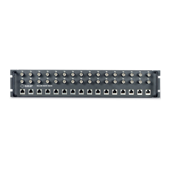
CHAPTER 4: Installation 4. Installation 4.1 The G.703 Balun Chassis The G.703 Balun Chassis can accommodate up to 16 G.703 Balun Modules. Measuring only 3.5" high, the Chassis is designed to occupy only 2U in a 19-inch rack. Sturdy front handles allow the Chassis to be extracted and transported conveniently. - Page 17 G.703 MODULES, MODULE PANEL, AND CHASSIS 4.2 Installing a Module in the Chassis The Chassis is made up of a 2U-high rack chassis and individually mountable G.703 Balun Modules. You can purchase a fully populated 16-port rack (part number MT243A) or you may purchase individual modules. Refer to Figure 4-2 as a guide and follow the steps below to install each additional module into the chassis.
- Page 18 CHAPTER 4: Installation Star Washer (behind the module) Spacer Lexan Shield Modules Hex Nut Lock Washer Figure 4-2. Mounting the Module to the Rack. 5. Secure the Module by connecting a lock washer and a hex nut on each screw.
- Page 19 G.703 MODULES, MODULE PANEL, AND CHASSIS 4.3 Connecting the 75-Ohm BNC Ports The 75-ohm BNC ports on the front of the Chassis are labeled “TX” (Transmit Data Output) and “RX” (Receive Data Input). Simply connect the G.703 lines as follows: G.703 Network G.703 Balun Module BNC Connector...
- Page 20 CHAPTER 4: Installation 4.4 Connecting the 120-Ohm RJ-45 Ports The pin configuration of the 120-ohm twisted-pair port is shown below: RJ-45 Pins Function 1 ....TX Output 2 ....TX Output 3 ....TX Shield 4 ....RX Input 5 ....RX Input 6 ....RX Shield 7 ....No connection 8 ....No connection Install the twisted-pair wires by making the following...
-
Page 21: Appendix A: Pin Assignments
G.703 MODULES, MODULE PANEL, AND CHASSIS Appendix A: Pin Assignments 120-Ohm Twisted-Pair Interface RJ-45 Jack Pin No./Signal 1- Transmit Data Out 2- Transmit Data Out 3- Transmit Data Shield 4- Receive Data In 5- Receive Data In 6- Receive Data Shield 7- no connection 8- no connection... -
Page 22: Appendix B: Block Diagram
APPENDIX B: Block Diagram Appendix B: Block Diagram RJ-45 Shield RJ-45 Shield TX Shield RX Shield...
Need help?
Do you have a question about the Balun G.703 and is the answer not in the manual?
Questions and answers