Table of Contents
Advertisement
Quick Links
EncrypTight Enforcement Point (ETEP) Installation Guide
The EncrypTight
Guide provides detailed information on how to
install and configure EncrypTight Enforcement
Points.
Order toll-free in the U.S.: Call 877-877-BBOX (outside U.S. call 724-746-5500)
Customer
FREE technical support 24 hours a day, 7 days a week: Call 724-746-5500 or fax 724-746-0746
Support
Mailing address: Black Box Corporation, 1000 Park Drive, Lawrence, PA 15055-1018
Information
Web site: www.blackbox.com • E-mail: info@blackbox.com
Download from Www.Somanuals.com. All Manuals Search And Download.
Enforcement Point Installation
™
BLACK BOX
ET0010A
ET0100A
ET1000A
ET10000A
®
Advertisement
Table of Contents

Subscribe to Our Youtube Channel
Related Manuals for Black Box EncrypTight ET0010A


Summary of Contents for Black Box EncrypTight ET0010A
- Page 1 Customer FREE technical support 24 hours a day, 7 days a week: Call 724-746-5500 or fax 724-746-0746 Support Mailing address: Black Box Corporation, 1000 Park Drive, Lawrence, PA 15055-1018 Information Web site: www.blackbox.com • E-mail: info@blackbox.com Download from Www.Somanuals.com. All Manuals Search And Download.
- Page 2 Download from Www.Somanuals.com. All Manuals Search And Download.
-
Page 3: Table Of Contents
About This Document .......................7 Purpose ........................7 Intended audience .....................7 Assumptions ......................7 Conventions used in this document ................7 Contacting Black Box Technical Support ................7 Product Overview ........................9 ETEP Introduction ........................9 ET0010A Physical Description ..................10 Front Panel Connectors .....................10 Status Indicators ......................11 Rear Panel .........................11... - Page 4 To cable the ET0010A: .....................34 Powering On the ET0010A .....................35 To power on the ETEP: ....................35 Installing the ET0100A ......................36 Cabling Requirements: ET0100A ...................36 Unpacking the Shipping Carton: ET0100A ..............37 Rack-Mount Installation: ET0100A ................37 To install the ETEP in a rack: ...................38 Connecting the Cables: ET0100A ..................38 To cable the ET0100A: .....................38 Powering on the ET0100A .....................39...
- Page 5 Setting the Date and Time ....................61 To set the date and time: ...................61 Entering a Throughput License .....................62 To add a license from the command line: ..............62 To view the ETEP throughput speed: ...............63 Configuration Example ......................63 Managing the ETEP ......................63 Maintenance ..........................65 Preventative Maintenance .....................65 What To Do If an Appliance Fails ..................65...
- Page 6 Emissions ........................79 FCC Information (USA) ...................79 Interference-Causing Equipment Standard Compliance Notice (Canada) ....79 European Notice .......................80 ET0100A Cabling .....................80 ET1000A Regulatory Information ..................80 Safety ........................80 Immunity ........................80 Emissions ........................80 FCC Information (USA) ...................80 Interference-Causing Equipment Standard Compliance Notice (Canada) ....81 European Notice .......................81 ET1000A Regulatory Information ..................81 Safety ........................81...
-
Page 7: About This Document
About This Document Purpose The ETEP Installation Guide describes how to cable and install the Black Box™ ETEP Black Box Enforcement Point. Intended audience This document is intended for use by network technicians and security administrators who are familiar with setting up and maintaining network equipment. - Page 8 About This Document ETEP Installation Guide Download from Www.Somanuals.com. All Manuals Search And Download.
-
Page 9: Product Overview
Product Overview ETEP Introduction The EncrypTight Enforcement Point (ETEP) Variable Speed Encryptors (VSEs) are purpose-built encryption appliances that provide multi-layer data protection. With straightforward setup and configuration, the ETEP has the flexibility to provide Ethernet frame encryption for Layer 2 networks, IP packet encryption for Layer 3 networks, and Layer 4 data payload encryption for MPLS networks. -
Page 10: Et0010A Physical Description
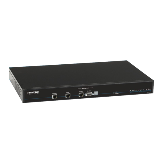
The ET0010A is a rack-mountable encryptor that can run at speeds ranging from 3-50 Mbps. It has two data ports on the front panel labeled Remote and Local. The following sections describe the Black Box ET0010A connectors and LED indicators. -
Page 11: Status Indicators
ETEP Introduction Status Indicators The ET0010A status indictors are shown in Figure 3. The status indications are described in Table Figure 3 ET0010A Status Indicators Elements of Figure Power LED Alarm LED Status indicators Link indicators The following table describes how to interpret the ET0010A status indicators. Table 1 ET0010A Status Indicators Indicator Light... -
Page 12: Et0100A Physical Description
Product Overview Figure 4 ET0010A Rear Panel and External Power Supply Elements of Figure External power supply power connector Rear panel power connector ET0100A Physical Description The ET0100A is a rack-mountable encryptor that can run at speeds ranging from 100–250 Mbps. The following sections describe the connectors and LED indicators that appear on the front and rear panels of the ET0100A. -
Page 13: Rear Panel
ET0100A Physical Description Figure 6 ET0100A LED Indicators Elements of Figure Diagnostic display Alarm LED Link indicators Power indictor The following table describes how to interpret the LEDs on the ET0100A front panel. Table 2 ET0100A Front Panel LED Indicators Indicator Light State Indication... -
Page 14: Et1000A Physical Description
Product Overview Figure 7 ET0100A Rear Panel Elements of Figure Power receptacle Product ID label ET1000A Physical Description The ET1000A is a rack-mountable 1 Gbps encryptor with dual power supplies. It can operate at speeds ranging from 500 Mbps–1 Gbps. The following sections describe the ET1000A connectors and LED indicators. -
Page 15: Led Indicators
ET1000A Physical Description LED Indicators The ET1000A LED indicators are shown in Figure 9. The LEDs are described in Table Figure 9 ET1000A LED Indicators Elements of Figure Power LED Alarm LED Diagnostic display Link indicators: 10/100 Ethernet management port Link indicators: Gigabit management port Link indicators: Aux1, Remote and Local ports Power supply status LEDs... -
Page 16: Rear Panel
Product Overview Table 3 ET1000A Front Panel LED Indicators Indicator Light State Indication Power supply status Power supply is not operational. Possible causes include power supply unplugged, power supply removed from chassis, or a malfunction. Power supply is operational. a. Gigabit links include the remote and local data ports, gigabit Ethernet management port, and Aux1 port. Rear Panel The ET1000A rear panel is shown in Figure... -
Page 17: Et10000A Physical Description
ET10000A Physical Description ET10000A Physical Description The ET10000A is a rack-mountable 10 Gbps encryptor with dual power supplies. It can operate at speeds ranging from 2.5–10 Gbps. The following sections describe the ET10000A connectors and LED indicators. Front Panel Connectors The ET10000A front panel connectors are shown in Figure Figure 11... - Page 18 Product Overview Figure 12 ET10000A LED Indicators Elements of Figure Alarm LED Power LED Diagnostic display Link indicators: 10/100 Ethernet management port Link indicators: Gigabit management port Link indicators: 10/100 Ethernet Aux ports Link indicators: Gigabit Aux ports Link indicators: Remote port Link indicators: Local port Secure traffic LED Power supply status LEDs...
-
Page 19: Rear Panel
ET10000A Physical Description Table 4 ET10000A Front Panel LED Indicators Indicator Light State Indication Gigabit link status (green) Loss of signal on the Gigabit link. The Gigabit link is up but no traffic is passing over the interface link. Blinking Indicates the presence of traffic on the Gigabit link. -
Page 20: Features
Product Overview Features ETEPs share many of the same features and capabilities across hardware models, as shown in Table Hardware differences between the ETEP models are summarized in Table Table 5 ETEP Hardware Comparison Dual Form Data Port Data Port Mgmt Port Auxiliary Power... -
Page 21: Specifications
Specifications Table 6 ETEP Feature Summary Category Feature Device Management • EncrypTight Manager software for device and policy management • Out-of-band management • Alarm condition detection and reporting • Syslog support • SNMPv2c and SNMPv3 managed object support • Audit logging •... - Page 22 Product Overview Table 7 ET0010A Mechanical and Environmental Specifications Category Specification ET0010A 19 inch rack mount design Electrical/Mechanical Dimensions 1u tamper evident chassis Dimensions: 1.6” H x 9.1” W x 7.1” D Weight (without external power supply),1 pound 10 ounces External power supply: •...
- Page 23 Specifications Table 9 ET1000A Mechanical and Environmental Specifications Category Specification Interfaces (2) Gigabit Ethernet ports for encrypting and decrypting traffic (single mode, multimode, or copper) 10/100 Mbps auto-sensing Ethernet LAN port for management RS-232C port for management (1) Auxiliary Gigabit port for data traffic (not enabled) (1) Gigabit Ethernet port for management (not enabled) ET1000A 19 inch rack mount design...
-
Page 24: Mib Support
“ET10000A Regulatory Information” on page MIB Support This section identifies the Black Box MIBs and standard MIBs that are used to manage ETEP appliances. The MIBs can be loaded into a management station SNMP client application, which typically includes a MIB browser and an SNMP trap receiver. - Page 25 MIB Support Table 11 ETEP MIBs Module Filename BLACKBOX-SMI BLACKBOX-SMI.txt BLACKBOX-CRYPTO-MIB BLACKBOX-CRYPTO-MIB.txt SNMPv2-CONF SNMPv2-CONF.txt SNMPv2-MIB SNMPv2-MIB.txt SNMPv2-SMI SNMPv2-SMI.txt SNMPv2-TC SNMPv2-TC.txt ETEP Installation Guide Download from Www.Somanuals.com. All Manuals Search And Download.
- Page 26 Product Overview ETEP Installation Guide Download from Www.Somanuals.com. All Manuals Search And Download.
-
Page 27: Installation
The ETEP contains a lithium battery, which users should not attempt to replace. Battery replacement must be performed by qualified Black Box personnel. Risk of explosion if battery is replaced by an incorrect type. Used batteries should be disposed of according to the manufacturer’s instructions. -
Page 28: Etep Site Preparation
ETEP in a standalone deployment. See the EncrypTight Manager User Guide for additional third party software you may want to install when using in EncrypTight Manager to manage Black Box appliances. Table 12 Third party management station software Software How it’s used... -
Page 29: Firewall Ports
Grounding • Maintain reliable grounding of a rack-mounted ETEP. Pay particular attention to supply connections other than direct connections to the branch circuit, such as the use of power strips. Maintenance • Allow at least 19 inches (48.3 cm) of clearance at the front of the rack for maintenance. Use a cable- management system to help keep cables organized, out of the way, and free from kinks or bends that degrade cable performance. -
Page 30: Rack Mount Installation
Installation Rack Mount Installation To mount the ETEP in a standard 19-inch equipment rack, have the following tools and materials available: External power supply • Two mounting brackets, supplied in the Accessory Kit • (4) small black screws and (4) large #10-32 screws, supplied in the Accessory Kit •... - Page 31 Figure 15 Attach mounting brackets to the bottom panel. ET0010A is shown below. 3 Turn the ETEP face up and locate the external power supply. With the label side facing down, place the power supply in the mounting bracket cradle and snap it into place, as shown in Figure Figure 16 Power supply installed in mounting bracket cradle on the ET0010A...
-
Page 32: Solid Surface Installation
Installation Figure 17 Insert the power supply cable into the connector on the rear panel 5 Attach the mounting brackets to the rack’s front supports with the large #10-32 screws (item 1 in Figure 23), using a #2 Phillips screwdriver. Insert two screws in each bracket, using the top and bottom holes. - Page 33 Figure 19 Screw holes for rubber feet installation on bottom of unit 3 Place one of the rubber feet over the hole and insert a screw into the opening (Figure 20). Tighten the screw. Figure 20 Rubber feet installed 4 Repeat step 3 for the remaining feet. 5 Turn the unit over so that it is resting on the rubber feet.
-
Page 34: Connecting The Cables: Et0010A
1 For initial setup, connect the RS-232 serial port directly to a PC or workstation. Using the null modem cable supplied by Black Box, insert the RJ-45 connector in the RS-232 port and connect the DB-9 female connector to your PC. This cable can be removed after initial setup is complete. -
Page 35: Powering On The Et0010A
Figure 22 ET0010A Cabling NOTE The Aux1 port on the ET0010A is not enabled in this release. Powering On the ET0010A Use the following procedure to power up the ETEP. Figure 23 Attaching the power cables on the ET0010A-402 To power on the ETEP: 1 Check that the power supply cable is properly inserted in the power connector on the ETEP rear panel. -
Page 36: Installing The Et0100A
ET0100A port, and may or may not be the same connector type required for the other end of the cable. Some cables are supplied by Black Box and others are user-supplied. -
Page 37: Unpacking The Shipping Carton: Et0100A
Installing the ET0100A Table 15 ET0100A Standard Cables ET0100A Port Cabling Supplied by... Remote and Local ports Shielded Category 5 straight User through cables (STP), RJ-45 connector a. The local, remote, and Ethernet management ports are auto-sensing for polarity. You can use shielded Category 5 straight through cables or crossover cables when connecting to these ports. -
Page 38: To Install The Etep In A Rack
Installation To install the ETEP in a rack: 1 Attach a mounting bracket to each side of the ETEP (near the front panel). Attach each bracket with three small screws provided in the Accessory Kit, using a #1 Phillips screwdriver. 2 Attach the ETEP to the rack’s front supports with the large screws, using a #2 Phillips screwdriver (Figure 24). -
Page 39: Powering On The Et0100A
Installing the ET0100A Figure 25 ET0100A Cabling Powering on the ET0100A Use the following procedure to power up the ET0100A. To power on the ET0100A: On the appliance’s rear panel, plug the power cord into the ET0100A power receptacle. Attach the •... -
Page 40: Installing The Et1000A
Installation Figure 27 Improperly seated ET0100A power cable When the appliance powers up, all LEDs illuminate (see Figure 28). The Alarm LED illuminates briefly and the diagnostic code LED displays 88 to verify that the diagnostic display segments are functioning. The power LED remains lit until the unit is powered off. -
Page 41: Cabling Requirements: Et1000A
ET1000A port, and may or may not be the same connector type required for the other end of the cable. Some cables are supplied by Black Box and others are user-supplied. -
Page 42: Unpacking The Shipping Carton: Et1000A
Installation NOTE To meet the requirements of FCC Part 15 and the EU EMC Directive 2004/108/EC, use only shielded Category 5 cables with the ET1000A Ethernet management port Unpacking the Shipping Carton: ET1000A Remove all product components from the shipping carton and compare the contents to the packing list. Keep all packaging in case it is necessary to return the unit. -
Page 43: To Install The Et1000A In A Rack
Installing the ET1000A To install the ET1000A in a rack: 1 Place the unit on a solid surface, with the top facing up. Position the mounting brackets on each side of the appliance, as shown in Figure Figure 29 Mounting bracket orientation 2 Attach the mounting brackets to each side of the unit using the 8 small black screws provided in the accessory kit, and a #1 Phillips screwdriver, as shown in Figure... -
Page 44: Grounding Of Dc Power Supply: Et1000A
Installation Grounding of DC Power Supply: ET1000A For DC Power Supply Only Rating -36 to -72Vdc + 0%, 6 - 4.5A For Earth Connection 1 Loosen the ground terminal screw. 2 Insert an earthing wire to earth. 3 Protective device of the DC power source is rated at 20A, which is physically connected in front of the DC power supply. -
Page 45: Powering On The Et1000A
Installing the ET1000A 3 Plug an SFP Gigabit transceiver into the ET1000A remote port. If you are using an optical SFP, insert the fiber cable in the SFP and connect the other end to the untrusted network, typically via a router port. -
Page 46: To Power On The Et1000A
Installation Figure 33 Dual power supplies on the ET1000A rear panel Elements of Figure Power cord clips Status LED for power supply 2 Power receptacle for power supply 2 Power receptacle for power supply 1 Status LED for power supply 1 To power on the ET1000A: 1 On the appliance’s rear panel, plug the power cords into the power receptacles for each power supply. -
Page 47: Installing The Et10000A
Installing the ET10000A During the boot process the ET1000A cycles through its startup tests, and the corresponding diagnostic codes are displayed. After the tests execute successfully, the diagnostic code display is solidly illuminated with code 00. NOTE During the boot process the ET1000A discards all traffic on its data ports. Once the appliance is operational, the default mode of operation passes all packets in the clear until you deploy security policies. -
Page 48: Cabling Requirements: Et10000A
ET10000A port, and may or may not be the same connector type required for the other end of the cable. Some cables are supplied by Black Box and others are user-supplied. -
Page 49: Unpacking The Shipping Carton: Et10000A
Installing the ET10000A NOTE The polarity of the ET10000A DC power cable is indicated via color coding with Yellow being + (plus), Black being - (minus), and Green being (Ground) Unpacking the Shipping Carton: ET10000A Remove all product components from the shipping carton and compare the contents to the packing list. Keep all packaging in case it is necessary to return the unit. -
Page 50: To Install The Et10000A In A Rack
Installation 1 ET10000A chassis Firmware and software is factory-installed on the unit. • 2 Accessory Kit Rack mount kit includes 2 mounting brackets, 16 small black screws, and 4 large silver screws • (#10-32) (2) Power cables (US) • (1) Shielded null modem cable with an RJ-45 connector at one end and a DB-9 female connector •... -
Page 51: Connecting The Cables: Et10000A
1 For initial setup, connect the RS-232 port directly to a PC or workstation. Using the null modem cable supplied by Black Box, insert the RJ-45 connector in the RS-232 port and connect the DB-9 female connector to your PC. This cable can be removed after initial setup is complete. -
Page 52: Powering On The Et10000A
Installation Figure 39 ET10000A Cabling NOTE The Aux ports, and USB and Gigabit management ports are not enabled in this release. Powering on the ET10000A This section lists important safety guidelines for the ET10000A power modules, and describes how to safely apply power to the appliance. -
Page 53: Power-Up Procedure
Installing the ET10000A Power-Up Procedure Follow the instructions in this section to safely apply power to the ET10000A. Figure 40 Dual power supplies on the ET10000A rear panel Elements of Figure Status LED for power supply 2 Status LED for power supply 1 Power receptacle for power supply 2 Power receptacle for power supply 1 To power on the ET10000A:... -
Page 54: Shutting Down The Etep
Installation Figure 41 ET10000A Front Panel Status Indicators Elements of Figure Alarm LED Power indicator Diagnostic display Power supply LEDs Shutting Down the ETEP It is important that a proper system shutdown is performed prior to powering off the appliance. The shutdown command halts all running tasks on the ETEP and prepares it for being powered off. - Page 55 Shutting Down the ETEP Example In the following example the user logs in as admin and shuts down the ETEP. pep login: admin Password: Last login: Tue Apr 8 15:12:21 2008 on ttyS0 Welcome admin it is Tue Apr 8 15:17:57 UTC 2008 admin>...
- Page 56 Installation ETEP Installation Guide Download from Www.Somanuals.com. All Manuals Search And Download.
-
Page 57: Initial Setup
Initial Setup Overview The following steps are required for initial setup of the ETEP: 1 Log in through a serial link. 2 Configure the management port. 3 Set the date and time. 4 Enter the throughput license. Logging In Through a Serial Link Initial setup is performed through a serial link to the RS-232 port. -
Page 58: Configuring The Management Port
Initial Setup 6 When you are successfully logged in, the command line prompt displays as shown below (password text is not displayed). admin pep login: Password: Last login: Tue Jan 29 19:18:59 2008 on ttyS0 Welcome admin it is Tue Jan 29 19:37:12 UTC 2008 admin>... -
Page 59: About Auto-Negotiation
Configuring the Management Port Figure 42 Management Port Default Gateway Elements of Figure ETEP Router Management workstation About auto-negotiation The default setting for the ETEP enables auto-negotiation, which negotiates the link speed, duplex setting, and flow control. Use the autoneg command if the device that the ETEP connects to from a particular port does not support auto-negotiation or flow control. - Page 60 Initial Setup ip <ip address> <subnet mask> [gateway] ip address Management port IP address, entered in dotted decimal notation. subnet mask IP subnet mask, entered in dotted decimal notation. gateway Specifies how to route traffic between the ETEP management port and the management station.
-
Page 61: Setting The Date And Time
Setting the Date and Time Example The following example sets the management port IPv4 address, subnet mask, and gateway for the ETEP as shown in Figure 42. Auto-negotiation is left at its default setting of enabled. admin> configure management-interface config> ip 192.168.10.10 255.255.255.0 192.168.10.1 man-if>... -
Page 62: Entering A Throughput License
Initial Setup hour 00-23 minutes 00-59 seconds 00-59 3 Type exit to return to the command prompt. Example admin> configure date 2008 10 11 15 30 00 config> config> exit Entering a Throughput License The method for entering licenses on the ETEP depends on your management software: For ETEPs that are managed exclusively through the command line, follow the procedure in this •... -
Page 63: To View The Etep Throughput Speed
Configuration Example To view the ETEP throughput speed: 1 At the command prompt, type show throughput-speed . Configuration Example The following example illustrates the commands used for initial setup of the ETEP to configure the following parameters: management IP address, subnet mask, and default gateway, auto-negotiation, date and time. - Page 64 Initial Setup CAUTION After entering FIPS Mode, the user must replace the admin and ops passwords from the default settings. See the user guide for your management software for details: ETEP CLI User Guide • EncrypTight Manager User Guide • ETEP Installation Guide Download from Www.Somanuals.com.
-
Page 65: Maintenance
Maintenance Preventative Maintenance Periodically perform maintenance on your ETEP. Keep components free of dust and other particulate matter. Examine cables for damage and ensure that airflow requirements have been met. On ETEP models that have fans, check the fans for reduced airflow caused by dust build-up and clean as necessary. No special maintenance is required. -
Page 66: Obtaining A License For Replacement Units
Maintenance Obtaining a License for Replacement Units When replacing the ETEP with a spare, the replacement ETEP will run at full throughput for a grace period. During the grace period, contact customer support to report the RMA unit and to receive a new license for the replacement. -
Page 67: Replacing The Et10000A Power Supply
5 Insert the power cord in the replacement power supply and secure it with the clip. 6 Reconnect power supplies 1 and 2 to their respective power sources. 7 Return the failed power supply to Black Box as directed by Customer Support. Replacing the ET10000A Power Supply CAUTION Disconnect all power cords before servicing the ET10000A. - Page 68 Maintenance Figure 46 The power supply bracket is secured with two screws 3 Locate the release lever at the top of the power supply (Figure 47). Press the release lever downward toward the black support support to release the power supply latch. Figure 47 Press the release lever downward to unlatch the power supply 4 Keeping the lever in the release position, pull the power supply outward to remove it from the chassis.
-
Page 69: Tamper Switch And Zeroization
7 Insert the power cord in the replacement power supply. 8 Reconnect power supplies 1 and 2 to their respective power sources. 9 Return the failed power supply to Black Box as directed by Customer Support. Tamper Switch and Zeroization The following ETEP models include a tamper switch: ET0010A, ET0100A, ET1000A, and ET10000A. -
Page 70: To Recover The Etep Following Zeroization
Maintenance To recover the ETEP following zeroization: Wait approximately 20 minutes for the zeroization process to complete. If you are connected to the ETEP through the serial port, you will see the following message: Power cycle required to reboot appliance After cycling the power, you will be able to configure and manage the ETEP from its factory default settings. -
Page 71: Rs-232 Serial Cable: Et0100A, Et1000A Models
Cable Pinouts RS-232 Serial Cable: ET0100A, ET1000A Models The RS-232 serial cable on the ET0100A, and ET1000A is a null modem cable with DB-9 connectors (female to male). Figure 51 ETEP100x Null Modem Serial Cable Table 25 ETEP100x Null Modem Pin Connection 2 Receive Data 3 Transmit Data 3 Transmit Data... - Page 72 Maintenance ETEP Installation Guide Download from Www.Somanuals.com. All Manuals Search And Download.
-
Page 73: Troubleshooting
Troubleshooting Symptoms and Solutions The following tables provide some solutions to common problems that may occur with your ETEP. LED Indicators Table 26 LED Indicators Symptom Explanation and Possible Solution No power light. • Make sure the power cable is attached and plugged in to both the device and the power outlet. -
Page 74: Error State
Troubleshooting Error State Table 27 Error State Symptoms and Solutions Symptom Explanation and Possible Solutions The Alarm LED is illuminated The ETEP enters an error state when a boot test fails, the operating temperature threshold is exceeded, signature errors are detected on critical files pertaining to policies and keys. -
Page 75: Diagnostic Code Display
Diagnostic Code Display Diagnostic Code Display ETEPs display self-test codes during boot up, in addition to operational status and error conditions. See the following sections for information about your appliance model. Status Codes: ET0010A The ET0010A status LEDs display self-test codes during boot up. After the ET0010A boots, the status LEDs reflect the operational state of the appliance. -
Page 76: Diagnostic Codes: Et0100A, Et1000A And Et10000A
Alarm light illuminates if diagnostic tests 01-04 fail. In the event of a failure, make a note of the code and of the error message on the console, and then contact Black Box customer support. After the ETEP boots up the diagnostic display reflects the operational state of the appliance. -
Page 77: Environmental And Regulatory Information
Black Box’ position that its network security products qualify for the lead-in-solder exemption. Black Box is committed to completely eliminating its use of RoHS prohibited materials as that becomes technically feasible. We are constantly monitoring the availability of lead-free components and the progress of the lead-free manufacturing processes. -
Page 78: Et0010A Regulatory Information
Environmental and Regulatory Information ET0010A • ET0100A • ET1000A • ET10000A • ET0010A Regulatory Information The ET0010A and ET0010A-Desktop, have received a statement of compliance for the items listed in the following sections: Application of Regulations: FCC Title 47, Part 15, Subpart B, EMC Directive 2004/108/EC •... -
Page 79: European Notice
Regulatory Information European Notice Products with the CE Marking comply with both the EMC Directive (2004/108/EC) and the Low Voltage Directive (2006/95/EC) issued by the Commission of the European Community. ET0100A Regulatory Information The ET0100A, part number 410-032-002, has received a statement of compliance for the items listed in the following sections. -
Page 80: European Notice
Environmental and Regulatory Information European Notice Products with the CE Marking comply with both the EMC Directive (2004/108/EC) and the Low Voltage Directive (2006/95/EC) issued by the Commission of the European Community. ET0100A Cabling WARNING Use only shielded cables to connect I/O devices to this equipment. You are cautioned that changes or modifications not expressly approved by the party responsible for compliance could void your authority to operate the equipment. -
Page 81: Interference-Causing Equipment Standard Compliance Notice (Canada)
Regulatory Information Interference-Causing Equipment Standard Compliance Notice (Canada) “The Class A digital apparatus complies with Canadian ICES-003.” “Cet appareil numerique de la class A est conforme a la norme NMB-003 du Canada.” European Notice Products with the CE Marking comply with the European Council Directive 2004/108/EC. ET1000A Regulatory Information The ET1000A, part number 410-032-103, has received statements of compliance for the items listed in the following sections:... -
Page 82: Interference-Causing Equipment Standard Compliance Notice (Canada)
Environmental and Regulatory Information Interference-Causing Equipment Standard Compliance Notice (Canada) “The Class B digital apparatus complies with Canadian ICES-003.” “Cet appareil numerique de la class B est conforme a la norme NMB-003 du Canada.” European Notice Products with the CE Marking comply with the European Council Directive 2004/108/EC. ET10000A Regulatory Information At the time of publication of this manual, testing was in process for the ET10000A, part number 410- 032-702. - Page 83 Regulatory Information 13 Los cables de la fuente de poder deben ser guiados de tal manera que no sean pisados ni pellizcados por objetos colocados sobre o contra ellos, poniendo particular atención a los contactos y receptáculos donde salen del aparato. 14 El equipo eléctrico debe ser limpiado únicamente de acuerdo a las recomendaciones del fabricante.
- Page 84 Environmental and Regulatory Information ETEP Installation Guide Download from Www.Somanuals.com. All Manuals Search And Download.
-
Page 85: Index
Index diagnostics alarm LED power up codes ET0010A 11 ET0010A description 75 ET0100A 13 ET0100A description 76 ET1000A 15 ET1000A description 76 ET10000A 18 diagrams autoneg command 60 ET0010A front panel connectors 10 battery replacement 27 front panel LEDs 11 booting the appliance rear panel connectors 12 ET0010A 35... - Page 86 Index initial setup maintenance auto-negotiation settings 59 recommendations 65 logging in through the serial port 57 replacing appliances 65 overview 57 management interface setting the management IP address 58 auto-negotiation 59 installation default gateway 58 ET0010A description 58 applying power 35 IP address 58 connecting the cables 34 MIB support 24...
- Page 87 Index regulatory information error state 74 ET0010A 78 LED indicators 73 ET0100A 79 power up codes ET1000A 80 ET0010A 75 ET10000A 82 ET0100A models 76 requirements ET0100A cables 36 unpacking the shipping carton ET1000A cables 41 ET0100A 37 ET10000A cables 48 ET1000A 42 safety guidelines 27 ET10000A 49...
- Page 88 24/7 Tech support available in 30 seconds or less. © Copyright 2012. All rights reserved. Black Box and the Double Diamond logo are registered trademarks, and EncrypTight is a trademark, of BB Technologies, Inc. Any third-party trademarks appearing in this manual are acknowledged to be the property of their respective owners.
- Page 89 Free Manuals Download Website h p://myh66.com h p://usermanuals.us h p://www.somanuals.com h p://www.4manuals.cc h p://www.manual-lib.com h p://www.404manual.com h p://www.luxmanual.com h p://aubethermostatmanual.com Golf course search by state h p://golfingnear.com Email search by domain h p://emailbydomain.com Auto manuals search h p://auto.somanuals.com TV manuals search h p://tv.somanuals.com...
Need help?
Do you have a question about the EncrypTight ET0010A and is the answer not in the manual?
Questions and answers