Table of Contents
Advertisement
Quick Links
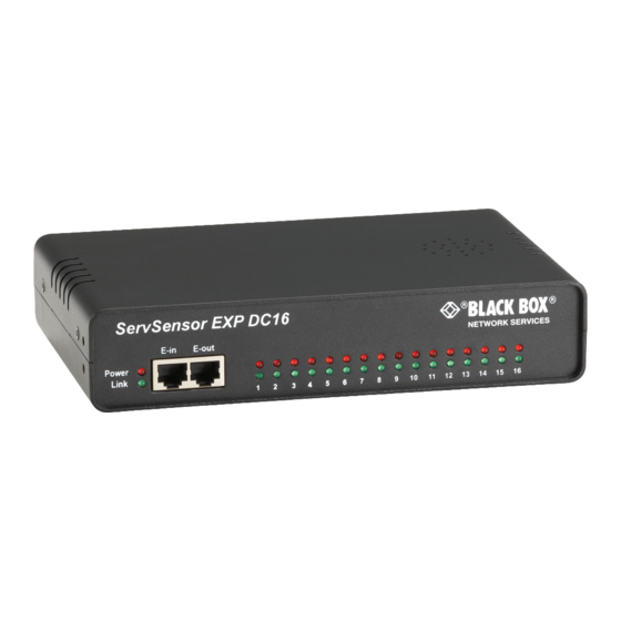
ServSensor EXP DC16
Adds 16 opto-isolated dry contacts,
so you can monitor more data points
from a ServSensor V4E.
Order toll-free in the U.S.: Call 877-877-BBOX (outside U.S. call 724-746-5500) •
Customer
FREE technical support 24 hours a day, 7 days a week: Call 724-746-5500 or fax 724-746-0746 •
Support
Mailing address: Black Box Corporation, 1000 Park Drive, Lawrence, PA 15055-1018 •
Information
Web site: www.blackbox.com • E-mail: info@blackbox.com
BLACK BOX
March 2010
EME1DC16
®
Advertisement
Table of Contents

Related Manuals for Black Box EME1DC16


Summary of Contents for Black Box EME1DC16
- Page 1 Order toll-free in the U.S.: Call 877-877-BBOX (outside U.S. call 724-746-5500) • Customer FREE technical support 24 hours a day, 7 days a week: Call 724-746-5500 or fax 724-746-0746 • Support Mailing address: Black Box Corporation, 1000 Park Drive, Lawrence, PA 15055-1018 • Information Web site: www.blackbox.com • E-mail: info@blackbox.com...
- Page 2 ServSensor EXP DC16 Trademarks Used in this Manual Black Box and the Double Diamond logo are registered trademarks of BB Technologies, Inc. Any other trademarks mentioned in this manual are acknowledged to be the property of the trademark owners. We‘re here to help! If you have any questions about your application or our products, contact Black Box Tech Support at 724-746-5500 or go to blackbox.com and click on “Talk to Black Box.”...
- Page 3 FCC and IC RFI Statements Federal Communications Commission and Industry Canada Radio Frequency Interference Statements This equipment generates, uses, and can radiate radio-frequency energy, and if not installed and used properly, that is, in strict accordance with the manufacturer’s instructions, may cause inter ference to radio communication. It has been tested and found to comply with the limits for a Class A computing device in accordance with the specifications in Subpart B of Part 15 of FCC rules, which are designed to provide reasonable protection against such interference when the equipment is operated in a commercial environment.
-
Page 4: Instrucciones De Seguridad
ServSensor EXP DC16 Instrucciones de Seguridad (Normas Oficiales Mexicanas Electrical Safety Statement) 1. Todas las instrucciones de seguridad y operación deberán ser leídas antes de que el aparato eléctrico sea operado. 2. Las instrucciones de seguridad y operación deberán ser guardadas para referencia futura. 3. -
Page 5: Table Of Contents
Table of Contents Table of Contents 1. Specifications ....................................... 6 2. Overview ......................................7 2.1 Introduction ....................................7 2.2 What’s Included .................................... 7 2.3 Hardware Description ..................................8 2.3.1 Front Panel ................................... 8 2.3.2 Back Panel.................................... 9 3. Installation ......................................10 3.1 Connecting to the Base Unit ................................10 3.2 Setting Up a Sensor (Standard Configuration) ..........................11 3.3 Setting Up a Sensor (Daisychained Configuration) ........................14... -
Page 6: Specifications
Components: Manufactured using highly integrated, low-power surface-mount technology to ensure long-term reliability Data Transfer Rate: 115.2 kbps Expandability/E-modules: Daisychain multiple E-modules, including EME1X8 and EME1DC16, uses standard RJ-45 connections and CAT5 LAN cable, connect up to 600 intelligent sensors Maximum Cable Length: 1000 ft. (300 m) -
Page 7: Overview
16 opto-isolated dry contacts. This increases the number of data points that can be monitoried from a single ServSensor V4E. 2.2 What’s Included Your ServSensor EXP DC16 package should contain the following items. If anything is missing or damaged, contact Black Box Technical Support at 724-746-5500 or info@blackbox.com. • ServSensor EXP DC16 •... -
Page 8: Hardware Description
Unit is operating in safe mode Used when the ServSensor EXP DC16 loads the operating system (OS) with a minimal set of drivers. If your device enters safe mode after rebooting, contact Black Box Technical Support at 724-746-5500 or info@blackbox.com. -
Page 9: Back Panel
Chapter 2: Overview 2.3.2 Back Panel Figure 2-2 shows the ServSensor EXP DC16’s back panel, and Table 2-3 describes its components. Figure 2-2. Back panel. Table 2-3. Back panel components. Number Component Description (16) 2-pin ports The 2-pin dry contact ports, numbered 1–16, are used to connect the input voltage. -
Page 10: Installation
ServSensor EXP DC16 3. Installation 3.1 Connecting to the Base Unit To connect the ServSensor EXP DC16 to the ServSensor V4E, follow the steps listed below. 1. Connect the cable to your chosen port. See Figure 3-1. Figure 3-1. E1 port. 2. -
Page 11: Setting Up A Sensor (Standard Configuration)
Chapter 3: Installation In the example shown in Figure 3-3, two expansion modules are connected from two separate expansion ports on the ServSensor. In the example shown in Figure 3-4, the same two modules are connected to one expansion port in a daisychain configuration. - Page 12 ServSensor EXP DC16 Figure 3-6. Summary page. The dry contact sensor should be listed along with its current reading and status. 4. Click on the dry contact sensor’s name (indicated in previous screen). The Sensors page appears. Figure 3-7. Sensors page. NOTE: You can also access this page by clicking on the Sensors tab at the top of the page.
- Page 13 Chapter 3: Installation Figure 3-8. Sensors menu. 6. Click on the dry contact sensor icon (or another type of sensor icon). 7. The page shown in Figure 3-9 appears. Figure 3-9. Sensor Settings page. As with the ServSensor V4E, the procedure for changing sensor values remains the same. For more information on sensor set- tings, refer to the ServSensor (EME134A) manual or individual sensor manual.
-
Page 14: Setting Up A Sensor (Daisychained Configuration)
ServSensor EXP DC16 3.3 Setting up a Sensor (Daisychained Configuration) This section describes the basic setup of a sensor in a daisychained configuration. It focuses on the dry contact sensor; however, this basic setup process applies to all compatible sensors. If you require information on specific functions of a particular sensor, then download the manual for that sensor from our Web site or locate it on your product CD. - Page 15 Chapter 3: Installation 3. When the unit is connected, the LEDs will enter the boot-up sequence indicating that the expansion module (EME1DC16) is communicating with your ServSensor V4E (EME134A). 4. Plug a sensor into one of the dry contact ports on the rear panel of the unit. In this example, we will use Port 1.
- Page 16 ServSensor EXP DC16 Figure 3-14. Sensors page. 7. Click on any available sensor icon (see Figure 3-15). The settings for that particular sensor will appear as shown in Figure 3-16. Figure 3-15. Temperature sensor settings icon. 724-746-5500 | blackbox.com Page 16...
- Page 17 Chapter 3: Installation Figure 3-16. Sensor Settings page. 724-746-5500 | blackbox.com Page 17...
-
Page 18: Notifications
ServSensor EXP DC16 4. Notifications Set up a notification to define what to do when the sensor gives a reading beyond your previously set thresholds. This allows you to determine how you will be notified that a sensor's reading has reached the specified parameters (high warning, critical, etc.). 4.1 Adding a Notification 1. -
Page 19: Snmp Traps
Chapter 4: Notifications Figure 4-2. Notification Wizard page. NOTE: Next you’ll see a sample notification. To learn what the other types of notifications do, refer to the separate notification manuals on your product CD. 4.2 SNMP Traps Set up a notification via SNMP trap, so that when your sensor reaches a certain threshold it will send a notification to your SNMP server. - Page 20 ServSensor EXP DC16 Figure 4-3. SNMP Trap screen. 5. Fill in the following information: • Enter a name for the SNMP notification. • Enter the IP address of the SNMP trap. 6. Press the “Add Trap Destination” button. 7. Input another trap or click the “Next” button. The screen shown in Figure 4-4 appears. Figure 4-4.
- Page 21 Chapter 4: Notifications 10. Select the expansion board and the sensor. Figure 4-5. Selecting the expansion board and sensor. 11. Select the status and the action. Figure 4-6. Selecting setting and trap name. NOTE: In the example above, the SNMP trap is bound to the temperature sensor that’s connected on Port 1. The trap will be sent when the sensor reads a “High Critical,”...
- Page 22 ServSensor EXP DC16 12. Once we have created the parameters for the SNMP trap, we need to make it active. To do this, go back to the “Notification” tab. It should look like the screen shown in Figure 4-7. Figure 4-7. Notification tab. 724-746-5500 | blackbox.com Page 22...
- Page 23 Chapter 4: Notifications 13. Select the sensor and SNMP trap parameters as before. Figures 4-8 and 4-9 appear. Select the expansion board, then select the sensor. Figure 4-8. Select the expansion board, then select the sensor. 14. Select the status, then select the action. Figure 4-9.
- Page 24 ServSensor EXP DC16 As shown in Figure 4-10, the SNMP trap has been added to the “Notification” page. Figure 4-10. Notification page. NOTE: To remove this trap and make it inactive, highlight the notification and click remove. NOTE: You can repeat this process to set up multiple SNMP traps for different sensors or for multiple SNMP servers. 724-746-5500 | blackbox.com Page 24...
- Page 25 About Black Box Black Box Network Services is your source for more than 118,000 networking and infrastructure products. You’ll find everything from cabinets and racks and power and surge protection products to media converters and Ethernet switches all supported by free, live 24/7 Tech support available in 20 seconds or less.
Need help?
Do you have a question about the EME1DC16 and is the answer not in the manual?
Questions and answers