
Related Manuals for Ecobee EMS Si


Summary of Contents for Ecobee EMS Si
- Page 1 ©2012 ecobee 477 Richmond Street West | #210 Toronto | Ontario | M5V 3E7 | Canada Toll free 1.877.932.6233 www.ecobee.com MA-EMSSi-01-rev1...
- Page 2 EMS Si Manual...
-
Page 3: Table Of Contents
Wiring Requirements INSTALLING THE EMS Si Step 1. Power Off HVAC Equipment Step 2. Remove Existing Thermostat Step 3. Install the EMS Si Step 4. Connect the Wiring Step 5. Power On HVAC Equipment NAVIGATING THE MENUS Using the Navigation Buttons... - Page 4 AUTOMATION Setting Up the Sensor Inputs CONNECTING TO THE INTERNET Setting Up WiFi and Obtaining a Registration Code Configuring a Web Portal Account USING YOUR EMS Si System Mode Weather Forecast Cleaning the EMS Si CONFIGURING YOUR EMS Si Configuring Personal Preferences...
-
Page 6: Getting Started
The ecobee EMS Si can maximize any building’s efficiency, reduce energy consumption and deliver significant cost savings Technical Support Our technical support team is available to answer your questions at 1.877.932.6233, or via... -
Page 7: Before You Begin
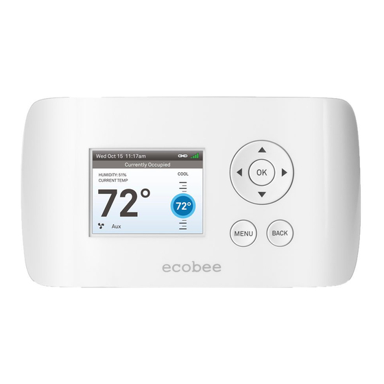
This manual explains the procedures for installing the ecobee EMS Si. Please read it carefully before beginning the installation. The EMS Si is designed to be mounted on the wall in a convenient location. MENU BACK ecobee Caution: Disconnect electric power to the HVAC system before installing this product. -
Page 8: Hvac System Compatibility Information
HVAC System Compatibility Information The EMS Si is designed to operate with low- voltage heating and cooling systems. It is not designed for use with line-voltage or millivolt heating and cooling systems. The EMS Si supports: Up to 2 heat and 2 cool stages on a conventional system. -
Page 9: Approvals
Approvals This product was designed and built in accordance to RoHS directive 2002/95/EC and contains no hazardous substances as defined by this directive. FCC Compliance Statement This equipment has been tested and found to comply with the limits for Class B digital devices, pursuant to Part 15 of the FCC Rules. -
Page 10: Specifications
FCC ID: WR9EBSTAT IC: 7981A-EBSTAT Warning: Changes or modifications not expressly approved by ecobee Inc. could void the user’s authority to operate the equipment. Specifications Temperature ranges Heat: 45 to 79 °F (7 to 26 °C) Cool: 45 to 92 °F (14 to 33 °C) Display: 40 to 100 °F (5 to 37 °C) -
Page 11: Wiring Requirements
Wiring Requirements The following table shows the maximum wire lengths allowed: Thermostat to HVAC Equipment 18 AWG 20 AWG 22 AWG 128 ft/380 m 80 ft/240 m 50 ft/150 m Terminal Description and Electrical Ratings Terminal Description Voltage Current Max Unused 1st stage compressor 30V AC... -
Page 12: Installing The Ems Si
Step 2. Remove Existing Thermostat Disconnect the wires to the existing thermostat and remove it from the wall (if you are installing the EMS Si in the same location). Step 3. Install the EMS Si The ideal location for the thermostat is approximately 5 ft (1.5 m) above floor level in the main living area. - Page 13 In an area that could restrict air flow To install the thermostat: 1. Gently separate the backplate from the thermostat. 2. Place the thermostat backplate on the wall. Make sure that any existing wires can be inserted through the opening for the wiring.
-
Page 14: Step 4. Connect The Wiring
To connect the thermostat to the equipment: 1. Connect the wires as shown in the wiring diagrams. 2. Attach the EMS Si to the backplate. Ensure that the pins on the thermostat align with the terminal block on the backplate. - Page 15 1-stage Furnace 1-stage AC EMS Si Thermostat Single stage heat/cool...
- Page 16 1-stage Furnace 2-stage AC EMS Si Thermostat Single stage heat, dual stage cool...
- Page 17 2-stage Furnace 1-stage AC EMS Si Thermostat Dual stage heat, single stage cool...
- Page 18 2-stage Furnace 2-stage AC EMS Si Thermostat Dual stage heat, dual stage cool...
- Page 19 Air Handler 1-stage Heat Pump Y/Y2 EMS Si Thermostat Single stage heat pump with auxiliary heat...
- Page 20 2-stage Heat Pump Air Handler Y/Y2 EMS Si Thermostat Dual stage heat pump with auxiliary heat...
- Page 21 Air Handler 1-stage AC Boiler EMS Si Thermostat * Remove RH/RC factory jumper C terminal to be connected to heating transformer common Boiler with air handler and single-stage cool...
- Page 22 Air Handler 1-stage AC 2-stage Boiler EMS Si Thermostat * Remove RH/RC factory jumper C terminal to be connected to heating transformer common Dual stage boiler with air handler and single stage cool...
- Page 23 2-stage AC Air Handler Boiler EMS Si Thermostat * Remove RH/RC factory jumper C terminal to be connected to heating transformer common Single stage boiler with air handler, dual stage cool...
- Page 24 2-stage AC Air Handler 2-stage Boiler EMS Si Thermostat * Remove RH/RC factory jumper C terminal to be connected to heating transformer common Dual stage boiler with air handler, dual stage cool...
-
Page 25: Step 5. Power On Hvac Equipment
Using the Navigation Buttons The navigation buttons located on the right of the EMS Si let you select options and control the EMS Si. ▲ On the Home screen, press ▲ to (up) increase the temperature set point by 1°F... - Page 26 (right) ▶ On the Home screen, if Auto mode is enabled, press ▶ to switch between heat and cool set points. For menus, press ▶ to choose the currently highlighted option. On a menu screen, press to choose the currently highlighted option. If a configuration option is selected, pressing will keep its new value and return back to the previous screen.
-
Page 27: Configuring The Hvac Settings
CONFIGURING THE HVAC SETTINGS The first step after installing the EMS Si is to configure the settings for the various devices (such as a furnace or air conditioner) that are being connected. Equipment To configure the The Equipment settings let you configure the equipment settings: devices connected to the thermostat. - Page 28 from running when the outdoor temperature is too low, thus resulting in damage to the compressor. You can also set this value to determine when you want the auxiliary heat (if installed) to engage to help meet the set temperature. The temperature range is adjustable from 0 to 65 °F (–17.8 to 18.3 °C) or can be completely disabled.
- Page 29 Heat Fan Control Configures the furnace fan to be controlled by the EMS Si or the HVAC system during heat cycles. Normally the HVAC system controls the fan during heat cycles. Air Conditioner Configures up to 2 stages of air conditioning.
-
Page 30: Thresholds
Thresholds To configure threshold This section configures the temperature and settings: time thresholds associated with the heating and cooling equipment. From the Home screen, press MENU. You must configure the Equipment settings Select Settings ▶ (page 10) before setting the thresholds. Only the Installation Settings. - Page 31 (if installed) to engage to help meet the set temperature. The temperature range is adjustable from 0 to 65 °F (–17.8 to 18.3 °C) or can be completely disabled. Note: You need an internet connection for this feature to operate properly. Aux Heat Settings Max Outdoor Temperature Configures the...
-
Page 32: Advanced Settings
in longer cycle times. The temperature range is adjustable from 0 to 3 °F (0.3 to 1.7 °C) in 0.5°F (0.3°C) increments. Cool Dissipation Time The amount of time the fan will run after the cool has been turned off. Running the fan for a period of time allows for any cooled air left in the ducts to circulate throughout the home. - Page 33 next stage. Options are Auto (default) and 10 to 120 minutes. Comp to Aux Temp Delta The maximum amount of time this stage will run before engaging the next stage. Options are Auto (default) and 1 to 10 °F (0.6 to 5.6 °C). Comp to Aux Runtime The minimum difference between the current temperature...
-
Page 34: Reset Hvac Equipment Settings
Reset HVAC Equipment Settings You can quickly restore all HVAC equipment To reset the EMS Si: settings on the EMS Si back to their factory From the Home screen, defaults. Any user setting (not related to the press MENU. -
Page 35: Rebooting The Ems Si
Rebooting the EMS Si You can reboot the EMS Si by pressing the physical hardware reset button, located through an opening in the bottom left corner of the EMS Si. Rebooting will not alter programming or configuration options. Reset button... -
Page 36: Configuring Reminders And Alerts
Configuring Reminders and Alerts To configure Reminders The Reminders and Alerts list displays the and Alerts reminders and alerts described below. From the Home screen, HVAC Service press MENU. The HVAC Service (maintenance) reminder Reminders and Select generates an alert telling the homeowner that Alerts. -
Page 37: Alerts
40 °C). Display Alerts on Thermostat Select No if you do not want any of the alerts to be displayed on the EMS Si screen. Alerts will continue to be displayed on the web portal and sent via email. -
Page 38: List Of Alerts
HVAC system due for regular Maintenance Reminder maintenance. Auxiliary Heat Run Auxiliary heat source is running Time too often. Your EMS Si auxiliary heat has Auxiliary Outdoor Temperature been called to run when the outdoor temperature exceeds the programmed set point. -
Page 39: Automation
AUTOMATION The EMS Si can be configured to perform actions based on the status of its 2 dry contact inputs. You can have multiple actions per input. You can also have the same input perform different actions when it is open or closed. For example, if... - Page 40 Do Nothing No specific action will occur. Switch to Occupied* Switches the system to the Occupied program when the input is activated. Switch to Unoccupied* Switches the system to the Unoccupied program when the input is activated. * The Economizer and/or Occupancy relay outputs, if configured, will also be switched to the appropriate state when this input is configured and activated.
- Page 41 input is cleared. Send Alert Enables the system to send an alert when the input has been activated. Send Update Log Enables the system to log when this input is activated. Activation Delay Configures time delay from when the input detects the active state to when the action programmed in the Type section is performed by the system.
- Page 42 If Adjust Temperature is chosen as the Type you will also be presented with the following options: Decrease Heat Temp Allows you to program the number of degrees that the heat set temperature will be adjusted by once an input has been activated. A positive number increases the heat set point and a negative number decreases the heat set point Increase Cool Temp Allows you to program...
-
Page 43: Connecting To The Internet
CONNECTING TO THE INTERNET Connect your EMS Si to the Internet so you can control it from your own personalized, secure ecobee Web Portal, smartphone, or tablet. From the Web Portal, you can: Program, configure and control your EMS Si. -
Page 44: Setting Up Wifi And Obtaining A Registration Code
Setting Up WiFi and Obtaining a Registration Code To set up WiFi: The EMS Si uses your home WiFi network to connect to the Internet. First, enable WiFi on the From the Home screen, EMS Si (see instructions to the right). -
Page 45: Configuring A Web Portal Account
See WiFi on page 52. Configuring a Web Portal Account After setting up WiFi on your EMS Si and obtaining the registration code, you need to configure your Web Portal account. 1. From a web browser on a PC, visit www.ecobee.com... - Page 46 5. Enter your address, contact, and user account information. Click Submit. Your EMS Si is now registered. You can now monitor and control your EMS Si from the Web Portal or from your smartphone or tablet. Re-registering the EMS Si...
-
Page 47: Using Your Ems Si
Press to decrease the temperature set point by 1°F (0.5°C). If the EMS Si is set to Auto mode, press ◀ to select the Cool setting. If the EMS Si is set to Auto mode, press ▶ to select the Heat setting. -
Page 48: System Mode
Turns on the fan when the system is heating or cooling your home, or to satisfy the minimum fan “on” time. When you switch between Auto and ON in fan control, the EMS Si will prompt you with the following:... - Page 49 After the fan mode is changed and you return to the home screen, the EMS Si will indicate that it is in a Hold state. The temperature setting will also be set to Hold. Press to revert the fan mode back to the weekly schedule fan and temperature settings.
-
Page 50: Weather Forecast
4-day and 24-hour forecast. Cleaning the EMS Si You can clean the EMS Si’s screen by spraying water or any mild, non-abrasive household cleaner on to a clean cloth. Wipe the surface of the screen with the dampened cloth. -
Page 51: Configuring Your Ems Si
The Preferences menu has settings for Preferences: personalizing your EMS Si. From the Home screen, Name press MENU. You can customize the name of your EMS Si to Settings ▶ Select suit your needs (i.e. Main Floor). This is useful Preferences. - Page 52 Brightness Select Set the Active brightness intensity. Set the Standby (idle screen) brightness intensity. Set the minimum time the EMS Si will stay in active brightness before switching to standby brightness. Hold Action Whenever you manually adjust the set temperature, the EMS Si will indicate you are in a “Hold”...
-
Page 53: Access Control
Web Portal or from the ecobee smartphone/ tablet application. Access Control You can protect your EMS Si so that certain features will require the user to enter a 4-digit access code. Use the arrow keys to highlight a number and then press OK. When you are done, select Save. -
Page 54: Temperature Range
Heat Temp Range Press ▲ ▼ select the maximum heat set point then press OK. Users will not be able to set the EMS Si to a temperature above this limit. Cool Temp Range Press ▲ ▼ to select the minimum cool set point and then press OK. -
Page 55: Utility Cpp Setting
Recovery Options Recovery options allow the EMS Si to learn how your heating and cooling system works, taking into account infrastructure, weather and historical operating performance so that your home is a comfortable temperature as soon as you walk in the door. - Page 56 (cool) from your existing set point. For example, if you program a 4 °F set forward, and your current cool set point is 76 °F, during an event your EMS Si set point will change to 80 °F until the event has expired. System Off...
-
Page 57: Wifi
Encryption (WEP, WEP128, WPA, or WPA2) Password (if encryption is used) WiFi Channel IP Address and IP Subnet Gateway Primary and Secondary DNS If you need to specify your EMS Si’s MAC address in your router’s configuration, you can obtain it from the About menu. -
Page 58: Creating Your Weekly Schedule
Your weekly schedule is down in the winter, to reduce heating energy. shown on the screen. By default, the EMS Si includes two configurable periods: Occupied Represents the period when the building or area is occupied. -
Page 59: Using The Weekly Schedule Editor
If your schedule changes, you can quickly and easily update the EMS Si settings on the device itself or online through your Web Portal. Using the Weekly Schedule Editor The Weekly Schedule editor lets you to set specific times, temperatures and furnace fan settings for each day of the week. -
Page 60: Scheduling A Calendar Event
Scheduling a Calendar Event The EMS Si’s Calendar Event feature helps To schedule a calendar you conserve energy while you are away for event: extended periods of time. It also ensures your From the Home screen, building is comfortable when you return. - Page 61 ON fan setting. In either mode, the EMS Si will ensure that when your calendar event ends, the EMS Si will revert to the regular settings.
-
Page 62: 3-Year Limited Warranty
During the warranty period, ecobee shall, at its option, repair or replace any defective Products, at no charge. Any replacement and/ or repaired device are warranted for the remainder of the original warranty or ninety (90) days, whichever is longer. - Page 63 Product until ecobee has received the defective Product). Product should be returned to the following address: ecobee Customer Service, 477 Richmond Street West, #210, Toronto, ON M5V 3E7, Canada. If the returned Product is found by ecobee to be defective and Customer is otherwise eligible to receive a replacement product, no amount shall be charged to Customer’s credit card;...
-
Page 64: End-User Software License Agreement
(a) ecobee if you have purchased the ecobee product directly from ecobee or; (b) to an ecobee authorized reseller or distributor if you have purchased the ecobee product from such entities, and the purchase price paid within fourteen days of its receipt of the return. - Page 65 Software and the User Manual is the sole and exclusive property of ecobee and/or its licensors), as the case may be. ecobee reserves all rights not expressly granted to LICENSEE hereunder, and for greater certainty, ecobee shall retain all intellectual property and other proprietary rights in and to the Software and the User Manual.
- Page 66 (e) use Software to access or in conjunction with any other thermostat monitoring services or products of any ecobee competitor. 8. Support: ecobee may in its discretion, without any obligation to do so and subject to the limitations of this EULA, provide LICENSEE with help-desk telephone support concerning LICENSEE’s use of the SOFTWARE to the extent provided for...
- Page 67 TO LICENSEE FOR ANY AND ALL ACTS OF THIRD PARTIES. NO OTHER PERSON IS AUTHORIZED TO EXTEND, VARY OR TRANSFER ANY PROVIDED WARRANTY ON BEHALF OF ecobee. THE ENTIRE RISK AS TO THE RESULTS AND PERFORMANCE AND USE OF THE SOFTWARE, SOFTWARE DOCUMENTATION AND ANY PROVIDED SUPPORT IS ASSUMED BY LICENSEE.
- Page 68 Software. 17. General Provisions: No delay or omission by ecobee to exercise any right or power it has under this EULA or to object to the failure of any covenant of...
- Page 69 Any waivers by ecobee must be in writing and signed by an authorized representative of ecobee. If any provision of this EULA is...
Need help?
Do you have a question about the EMS Si and is the answer not in the manual?
Questions and answers