Table of Contents
Advertisement
Advertisement
Table of Contents

Related Manuals for Ecobee ecobee4


Summary of Contents for Ecobee ecobee4
- Page 1 How to install your ecobee4...
- Page 2 happy You have joined a growing community of people who want to conserve energy, save money, and do something good for our planet. Let’s get started!
- Page 3 Download the ecobee app for customized installation instructions. Or continue reading!
- Page 4 First things first. Here’s what you’ll find in the box. ACC- ACC+ ecobee smart Room sensor Backplate Power Extender thermostat and stand Kit (PEK) Screws Control Board Thermostat Drywall plugs Install guide (this booklet), Trim plate room sensor manual, wire labels,...
- Page 5 You’ll also need these tools: Drill for mounting Small Phillips anchors (3/16” drill bit) flathead screwdriver screwdriver Hammer Pencil Wire stripper...
- Page 7 Guide 1 or Guide 2? Start here to find out. The steps in this section will help you decide which install guide you’ll use to complete the installation. These icons indicate useful tips and important reminders.
- Page 8 STE P 1 Power off your Heating, Ventilation, and Air Conditioning (HVAC) system by using the master switch or circuit breaker box. This is important for your safety. Look for your master switch or circuit breaker box in the basement, attic, utility closet, or behind a wall panel near the thermostat.
- Page 9 STEP 2 Confirm your system is off by turning on your heat (during winter) or your AC (during summer). Wait a few minutes—you should not feel air coming from your vents. If you have a boiler, check to see that the main flame is extinguished.
- Page 10 STE P 3 Remove your old thermostat cover from the wall. Many thermostats simply pop off or unclip from the base, while others may have screws that you will need to remove.
- Page 11 CHE CKPOIN T: CO MPATI BI LITY Does your old thermostat’s backplate have any of these indicators? 110 VAC 120 VAC WARNING HIGH VOLTAGE 240 VAC L1 L2 Sadly, you might Great, please not be compatible. continue to You can double-check here: the next page. ecobee.com/compatibility...
- Page 12 Take a picture of the wires connected to the terminals of your old thermostat. You may need to reference this photo later on. WARNING ecobee4 is designed for 24VAC with a 2A maximum current. Do not connect it to line (high) voltage or millivolt systems.
- Page 13 CHE CKPOIN T: C WI R E Do you have a C wire connected to your old thermostat? Continue to Continue to Guide 1 Guide 2...
- Page 15 GUID E 1 Install your ecobee with a C wire If you have a C wire, it will power your ecobee. You won’t need the Power Extender Kit included in the box.
- Page 16 CHECKPOINT: DO N’T SKI P AH EAD Have you completed steps 1–4 in the ‘Start Your Install’ section? Continue to Return to step 1 the next page in ‘Start Your Install’...
- Page 17 STEP 5 Carefully disconnect and label the wires from your old thermostat one at a time, using the labels provided. TIP 1 If you have a jumper between Rc, Rh, or R, leave it alone. Only label the wires that run from your wall into a terminal block. TIP 2 To install accessories (humidifier, dehumidifier or ventilator) please refer to the wiring diagrams in the ‘Extras’...
- Page 18 STEP 6 Unscrew the mounting plate of your old thermostat to remove it from the wall. WARNING Be careful, as some thermostats may contain mercury. Recycle your old thermostat safely with your local hazardous waste facility.
- Page 19 STE P 7 Decide if you want to use the trim plate with your ecobee. The trim plate is useful if you want to hide marks or holes left on the wall by your old thermostat. ACC- ACC+...
- Page 20 STE P 8: OP TIONAL If using the trim plate, align the mounting holes on the trim plate and backplate and press them into place together.
- Page 21 ST EP 9 Pull the wires through the hole in the middle of the backplate and then attach the backplate to the wall using the drywall anchors and screws provided. Use a 3/16” drill bit to drill a hole for the drywall plugs.
- Page 22 CHE CKPOINT: INSERT YO UR R WIR E(S) Do you have more than one R wire? (That includes R, R , and R ACC- ACC- ACC+ ACC+ Insert your wires: Insert your single R or R R, R , or R wire into the R terminal.
- Page 23 STEP 10 Insert your remaining wires into the side (not the front) of their corresponding terminal blocks. ACC- ACC+ Press the terminal block levers to insert the wires more easily.
- Page 24 STE P 1 1 Tug on the wires gently to ensure they are securely connected. When a wire has been connected correctly, the lever on that block will lower.
- Page 25 STEP 12 Carefully push any excess wires back into the hole and ensure there are no drafts coming from the hole(s) in the wall. Large holes behind your thermostat will affect temperature readings. Prevent drafts by covering the hole(s).
- Page 26 STE P 1 3 Gently press your ecobee into the backplate until it ‘clicks’ into place. If the thermostat ‘rocks’ or is not flush with the wall, be sure the excess wires are pushed all the way into the wall.
- Page 27 STEP 14 Turn the power to your HVAC system back on using the master switch or at the circuit breaker box.
- Page 28 STE P 1 5 Say hi to your new ecobee! The screen will power on and guide you through the setup and registration. If your thermostat does not power on, please see the troubleshooting tips in the ‘Extras’ section.
- Page 29 ALL DON E! Congratulations, you did it! To complete your setup, follow the instructions on your ecobee screen.
- Page 31 Install your ecobee without a C wire If you don’t have a C wire, you’ll need to use the Power Extender Kit (PEK) included to reliably power your ecobee.
- Page 32 CHE CKPOINT: DON’T SK IP AHEAD Have you completed steps 1–4 in the ‘Start Your Install’ section? Continue to Return to step 1 the next page in ‘Start Your Install’...
- Page 33 4 wires: W/W1, Y/Y1, G, and R (or Rc or Rh) or 3 wires: Y/Y1, G, and R (or Rc or Rh) Do you have these wires? Continue to Contact us the next page To proceed call 1.877.932.6233 The Power Extender Kit or email support@ecobee.com will work with your system!
- Page 34 STE P 5 Take your Power Extender Kit, wire labels, tools, your smartphone, and go to your HVAC system. ecobee wire labels Label wires at your: Thermostat Control Board Your HVAC system can most often be found in your basement or...
- Page 35 STEP 6 Open your HVAC system’s cover to reveal the control board. Control board WARNING HVAC systems contain high voltage wires. Use caution when working with the control board.
- Page 36 ST EP 7 Take a picture of the wires connected to your control board. You may need to reference this photo later on.
- Page 37 (ignore these) Wires going to your thermostat If you have wires connected to both R and R terminals at the control- board you may have a two transformer system. Please contact support to help you with installation: 1.877.932.6233 or support@ecobee.com.
- Page 38 STE P 9 Disconnect the wires labeled R, Y, G, and W from the control board.
- Page 39 STEP 10 Connect the wires you disconnected from the control board into their matching gray terminal blocks on the Power Extender Kit. Press the buttons to insert the wires more easily.
- Page 40 STE P 1 1 Tug on the wires gently to ensure they are securely connected. When a wire has been connected correctly, the button on that block will lower.
- Page 41 STEP 12 Connect the five white wires coming out of your Power Extender Kit to their corresponding terminals on the control board. Once again, tug on the wires gently to ensure they are securely connected.
- Page 42 CHE CKPOIN T: POWER EXTENDER K IT Check that you have installed the Power Extender Kit correctly. It should be installed between your thermostat wiring and your control board. BEFORE BEFORE AFTER AFTER...
- Page 43 STEP 13 Mount the Power Extender Kit inside your HVAC system, taking care not to strain the wires. Close the HVAC cover panel securely and return to your thermostat. Make sure your HVAC panel is fully closed. Some systems will not turn on if the cover panel has not been closed properly.
- Page 44 STE P 1 4 Back at your thermostat: Carefully disconnect and label the wires from your old thermostat one at a time, using the labels provided. If you have a jumper between Rc, Rh, or R, leave it alone. Only label the wires that run from your wall into a terminal block.
- Page 45 STEP 15 Unscrew the mounting plate of your old thermostat to remove it from the wall. WARNING Be careful, as some thermostats may contain mercury. Recycle your old thermostat safely with your local hazardous waste facility.
- Page 46 STE P 1 6 Decide if you want to use the trim plate with your ecobee. The trim plate is useful if you want to hide marks or holes on the wall left by your old thermostat. ACC- ACC+...
- Page 47 STEP 17: OP TIONA L If using the trim plate, align the mounting holes on the trim plate and backplate and press them into place together.
- Page 48 STE P 18 Pull the wires through the hole in the middle of the backplate and then attach it to the wall using the drywall anchors and screws provided. Use a 3/16” drill bit to drill a hole for the drywall plugs.
- Page 49 STEP 19 Remove the Rc, C, and PEK labels from the label sheet and attach them to the wires as shown below: R/Rc/Rh Rc Y PEK ACC- ACC+...
- Page 50 STE P 20 First, connect these 3 wires as shown: Rc, C, PEK Then, connect any remaining wires to their corresponding terminal. ACC- ACC+ Press the terminal block levers to insert the wires more easily.
- Page 51 C HECKPOINT: DON’T SK I P AH EAD Did you connect the correct wires to the Rc, C, and PEK terminals, as shown below? ACC- ACC+ Continue to Return to the next page Step 19...
- Page 52 STE P 20 Tug on the wires gently to ensure they are securely connected. When a wire has been connected correctly, the lever on that block will lower.
- Page 53 STEP 21 Carefully push any excess wires back into the hole and ensure there are no drafts coming from the hole(s) in the wall. Large holes behind your thermostat will affect temperature readings. Prevent drafts by covering the hole(s).
- Page 54 STEP 22 Gently press your ecobee into the backplate until it ‘clicks’ into place. If the thermostat ‘rocks’ or is not flush with the wall, be sure the excess wires are pushed all the way into the wall.
- Page 55 STEP 23 Turn the power to your HVAC system back on using the master switch or at the circuit breaker box.
- Page 56 STE P 24 Say hi to your new ecobee! The screen will power on and guide you through the setup and registration. If your thermostat does not power on, please see the troubleshooting tips in the ‘Extras’ section.
- Page 57 ALL DON E! Congratulations, you did it! To complete your setup, follow the instructions on your ecobee screen.
- Page 59 EXTR AS In here you’ll find: — Troubleshooting — Meet your ecobee — Wiring diagrams — Warranty and Legal...
- Page 60 TROUBLESHOOT ING If your ecobee doesn’t turn on, please try these steps: 1. Check that all wires are properly 2. Make sure your HVAC cover pan- inserted into the terminal blocks el is closed. Some systems will at the thermostat. Tug on the not turn on if the cover panel wires to ensure they are not loose.
- Page 61 Kit, make sure you inserted the inserted into the Rc terminal. wires into the correct terminals: Your R, Rc, or Rh wire ACC- ACC+ ecobee support is here to help: CALL EMAIL 1 877.932.6233 (North America) support@ecobee.com 1 647.428.2220 (International)
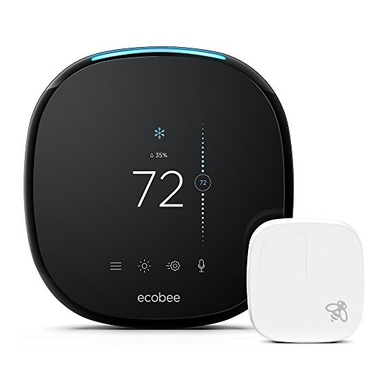
- Page 62 MEE T YOUR ECO BEE Here’s what you’ll see on the home screen: Slider to adjust System Mode Temperature Humidity Indoor Temperature Voice Control Weather Menu Quick Changes...
- Page 63 M EET YOUR ECOB EE And here’s what that means: System Mode Menu Shows your current ecobee setting Allows you to control your system, (heat/cool/auto/off). schedule a vacation, and more. Humidity Weather Shows the indoor humidity in Shows the local weather and forecast your home.
- Page 64 ME E T YO UR ECOBEE These system mode icons are shown on the Home screen and in Quick Changes. Heat Cool Your system is in heat mode. Your system is in cool mode. A white A white icon means your system icon means your system is off.
- Page 65 More common icons you’ll find: HOME SCREEN Menu Menu Weather Quick (with notification) Changes MENU Registration System Settings Schedule Vacation Alerts and Comfort Settings About Reminders COMFORT SETTINGS Home Away Sleep Custom 1 (of 5) VOICE Voice Control Microphone Off Push to Talk...
- Page 66 Y1 Y2 W1 W2 R C G Stage 2 heat Air Conditioner Furnace and cool, if applicable NOTE Do not connect any jumper wires between Rc and Rh. ecobee does this automatically. The R wire needs to go into the Rc terminal on your ecobee.
-
Page 67: Auxiliary Heat
W2 Y1 compressor and auxiliary Heat Pump Air Handler heat, if applicable NOTE Do not connect any jumper wires between Rc and Rh. ecobee does this automatically. The R wire needs to go into the Rc terminal on your ecobee. - Page 68 HUMI DI FI ER / DEHUMI DI FIER ( 1-WIRE SET UP) Step 1: Locate the humidifier/dehumidifer control and remove the plate. HUM/DHUM Thermidistat HUM/DHUM R C G Y W (24V) Furnace Control Board Humidifier/ Dehumidifier Solenoid...
- Page 69 HU MIDI FIE R / DEHUMI DI FIER ( 1-WIR E SETUP) Step 2: Wire the humidifier/dehumidifer as shown below. ACC- ACC+ (24V) G Y W Humidifier/ Furnace Dehumidifier Solenoid Control Board NOTE During setup, select 2-wire (ACC+, ACC-) accesory on the thermostat screen.
- Page 70 HUMI DI FI ER / DEHUMI DI FIER ( 2-WIR E S ETUP) Step 1: Locate the humidifier/dehumidifer control and remove the plate. R C U U Humidistat Humidifier/ Dehumidifier R C G Y W Furnace Control Board...
- Page 71 HUMIDI FI E R / DEH UMIDI FI ER ( 2-WIR E SET UP) Step 2: Wire the humidifier/dehumidifer as shown below. ACC- ACC+ Humidifier/ Dehumidifier R C G Y W Furnace Control Board NOTE During setup, select 1-wire (ACC+) accesory on the thermostat screen.
- Page 72 Air Conditioner Boiler or Heat Pump* *Stage 2 heat and cool, if applicable NOTE Do not connect any jumper wires between Rc and Rh. ecobee does this automatically. The R wire needs to go into the Rc terminal on your ecobee.
- Page 73 WIRIN G D IAGRAM Power Extender Kit thermostat wiring. ACC- ACC+ NOTE Do not connect any jumper wires between Rc and Rh. ecobee does this automatically. The R wire needs to go into the Rc terminal on your ecobee.
- Page 74 VE N TIL ATOR (2-WIR E SETUP) Step 1: Locate the ventilator timer control and remove the plate. Ventilator Timer Control Ventilator Timer Control R G (HI/LO) Ventilator /ERV/HRV...
- Page 75 VENTI L ATOR (2-WI RE SETUP) Step 2: Wire the ventilator as shown below. ACC- ACC+ R G (HI/LO) ERV/HRV NOTE During setup, select 2-wire (ACC+, ACC-) accesory on the thermostat screen.
- Page 76 L EG AL Approvals · Consult the dealer or an experienced radio/ TV technician for help. This product was designed and built in accordance to RoHS directive 2002/95/EC This device complies with part 15 of FCC and contains no hazardous substances as rules.
- Page 77 3-Year Limited Warranty L’exploitation est autorisée aux deux ecobee warrants that for a period of three (3) conditions suivantes : years from the date of purchase by the consumer (“Customer”), the ecobee4 (the 1.
- Page 78 Product should be returned to our address. warranted for the remainder of the original If the returned Product is found by ecobee warranty or ninety (90) days, whichever is to be defective and Customer is otherwise longer.
- Page 79 · Was installed improperly. ecobee’s sole responsibility shall be to repair This warranty gives you specific rights, and or replace the Product within the terms you may also have other rights which vary stated above.
- Page 80 We’re here to help. ecobee.com support@ecobee.com 1.877.932.6233 © 2016 ecobee, Inc. All rights reserved. ecobee and the ecobee logo are trademarks of ecobee Inc., registered in the U.S. and other countries. EB-STATE4-01 770-00034...
Need help?
Do you have a question about the ecobee4 and is the answer not in the manual?
Questions and answers
Can Ecobee Thermostat be used for duel fuel?
Yes, the Ecobee4 thermostat can be used for dual fuel systems.
This answer is automatically generated