Advertisement
- 1 GETTING STARTED
- 2 INSTALLING THE DEVICE
-
3
SYSTEM SET-UP
- 3.1 Navigating the Device
- 3.2 Configuring the Installer Settings
- 3.3 Installation Wizard
- 3.4 Equipment
- 3.5 Thresholds
- 3.6 Test Equipment
- 3.7 Sensors
- 3.8 View Wiring Diagram
- 3.9 Contractor Info
- 3.10 Reset Installation Settings
- 3.11 Reset All Setting
- 3.12 Setting up Reminders and Alerts
- 3.13 Alerts
- 3.14 List of Alerts
- 4 AUTOMATION
- 5 CONNECTING TO THE INTERNET
- 6 CREATING AN EMS WEB PORTAl ACCOUNT
-
7
USING THE DEVICE
- 7.1 What's on the Home Screen?
- 7.2 Feature Icons
- 7.3 Cleaning the Touch Screen
- 7.4 Viewing Details
- 7.5 Viewing Sensor
- 7.6 Preferences and Settings
- 7.7 Access Control
- 7.8 Temperature Range
- 7.9 Recovery Options
- 7.10 Economizer Setting
- 7.11 Device Name
- 7.12 Notes
- 7.13 Vacation Property
- 7.14 Programming the Device
- 7.15 Using the Program Wizard
- 7.16 Using the Editor
- 7.17 Scheduling a Calendar Event
- 7.18 Performing a Hardware Reset
- 8 Documents / Resources
GETTING STARTED
Welcome
The ecobee Energy Management System (EMS) is the newest technology designed for the commercial market. It is ideal in applications where a simple programmable Thermostat does not provide adequate controls and functionality and a full-scale building automation system is too complex and cost prohibitive. The ecobee EMS is user friendly, reduces a building's operating costs and delivers increased energy conservation.
Through a dedicated EMS Web Portal, users can remotely monitor, identify, analyze and trouble-shoot performance issues; manage the temperature and operational settings from a central location and take action without having to send a technician on-site, reducing the need for truck rolls.
The ecobee EMS will maximize any building's efficiency, reduce energy consumption and deliver significant cost savings.
Technical Support
Our technical support team is available to answer your questions at 1.877-9-ecobee (1.877.932.6233), or via email at support@ecobee.com.
Before You Begin
This product is intended to be installed by trained service professionals.
This manual explains the procedures for installing the ecobee Energy Management System (EMS). Please read it carefully before beginning the installation.
The ecobee EMS consists of two pieces of hardware:
- The ecobee Thermostat senses temperature, displays information and, if enabled, allows users to make adjustments directly on the touch screen.
![]()
- The Equipment Interface Module provides power to the Thermostat and is the interface for all of the HVAC equipment.
![]()


An optional 12 VDC power adaptor can be plugged into the Thermostat for product demonstrations or to power the Equipment Interface module in place of the normal 24Vac configuration.

Disconnect electric power to the system before installing this product. Failure to do so could result in electric shock and/or equipment damage.
All wiring must conform to your local electrical code.
Mercury Notice: This product does not contain mercury. If you are replacing a product that does contain mercury please contact your local waste-management authority for disposal instructions. Do not discard the old product in the regular trash.
HVAC System Compatibility Information
ecobee Energy Management System is designed to operate low-voltage heating and cooling systems. It is not designed for use with line-voltage or millivolt heating and cooling systems.
| Equipment Description | |
| Gas/Oil/Electric heating (up to three stages) | Yes |
| Air or ground source heat pump with auxiliary heat (up to four stages) | Yes |
| Standard electric cooling (up to two stages) | Yes |
| Two-wire hydronic heat | Yes |
| Central humidifier | Yes |
| Central dehumidifier | Yes |
| Heat Recovery Ventilator (HRV) | Yes |
| Energy Recovery Ventilator (ERV) | Yes |
| Economizer | Yes |
| Sensors with dry contact outputs | Yes |
WiFi Specifications
Your Smart Thermostat is designed to support:
- A 802.11 b g wireless router
- WEP 64, WEP 128, WPA1 and WPA2 encryption methods
- Dynamic or static IP addressing.
Approvals
Ecobee EMS was designed and built in accordance to RoHS directive 2002/95/EC and contains no hazardous substances as defined by this directive.
Specifications
Temperature Ranges
Heat: 45 – 79°F (7 – 26°C)
Cool: 58 – 92°F (14 – 33°C)
Display: 40 – 100°F (5 – 37°C)
Sensitivity: +/- 1°F (0.5°C)
Equipment Interface Operating: -40o to 160oF (-40o to 70oC)
Thermostat Operating: 32o to 130oF (0o to 55oC)
Humidity Range
Humidify: 20 to 50% R.H
Dehumidify: 30 to 60% R.H
Display: 0 - 90% R.H
Sensitivity: +/- 2% R.H.
Operating: 5 – 95% R.H non-condensing
Dimensions
Thermostat: 5.5"W x 3.25"H x 1"D (139.5mm H x 82.5mm W x 25mm D)
Equipment Interface: 4.6"W x 10"H x 1.3"D (118mm W x 254mm H x 32mm D)
Power
AC Transformer - 24 VAC - 3VA Minimum (not included)
Battery – CR2032 – 3V lithium coin cell (included),
Power Adaptor - #EB-PS-01 - 120V 50/60Hz to 12V DC 1A (not included)
Wiring Specifications
Refer to this table to determine maximum wire lengths allowed:
| Thermostat to Equipment Interface | |||
| 18 AWG | 20 AWG | 22 AWG | |
| 1250ft/380m | 790ft/240m | 500ft/150m | |
| Equipment Interface to Heating/Air Equipment | |||
| 18 AWG | 20 AWG | 22 AWG | |
| 128ft/39m | 80ft/24m | 50ft/15m | |
| Terminal Description and Electrical Ratings | |||
| Terminal | Description | Voltage | Current max |
| Y | 1st stage cooling | 30V AC | 3A |
| W (O/B) | 1st stage heating (or changeover) | 30V AC | 3A |
| G | Fan | 30V AC | 3A |
| W2(AUX) | 2nd stage heating (or 1st auxiliary heat) | 30V AC | 3A |
| R/H | Heat transformer return | 30V AC | 3A |
| R/C | Cool transformer return | 30V AC | 3A |
| ACC1 | 1st accessory relay | 30V AC | 3A |
| ACC1r | 1st accessory relay return | 30V AC | 3A |
| ACC2 | 2nd accessory relay | 30V AC | 3A |
| ACC2r | 2nd accessory relay return | 30V AC | 3A |
| ACC3 | 3rd accessory relay | 30V AC | 3A |
| ACC3r | 3rd accessory relay return | 30V AC | 3A |
| IN1 + | Input 1 + | Dry contact only | Dry contact only |
| IN1- | Input 1 - | Dry contact only | Dry contact only |
| IN2+ | Input 2 + | Dry contact only | Dry contact only |
| IN2- | Input 2- | Dry contact only | Dry contact only |
| +12v | 12V DC power to Thermostat | 8-14V DC | 600mA |
| GND | GND to Thermostat | - | - |
| D+ | Data + communication line | - | - |
| D- | Data – communication line | - | - |
INSTALLING THE DEVICE
Planning the Installation
Prior to installing the ecobee EMS, we recommend that you consider the following:
Where is the ideal location to mount the Equipment Interface?
- On a relatively flat surface
- In an environment that does not exceed the temperature or humidity level outlined in the specification section of this manual.
- In a location that is within the maximum wiring distance of the HVAC equipment and the Thermostat.
How do I intend to power the ecobee Energy Management System?
- Does the HVAC system control board have enough spare capacity to power this system?
- Do I need to provide a 24Vac transformer?
- Do I have access to a 120V electrical output to use the optional 12Vdc power adapter?
Where is the optimum location for the Thermostat?
- Within the maximum wiring distance to the Equipment Interface.
- Receiving good reception of WiFi signal (3 bars or more) from the location.
- If WiFi reception is sub-optimal, what will be relocated, the Thermostat or WiFi router?
- Do the temperature and humidity levels adequately represent the area controlled by the HVAC system?
How is the WiFi and Internet connection configured in this building?
- Do I have access to the customer's WiFi and/or internet connection?
- What information do I need to provide to the IT staff to ensure the ecobee EMS can successfully connect to their WiFi and/or internet connection?
Once you have planned your installation continue with the installation instructions.
Installing the Equipment Interface
To install the Equipment Interface:
- Choose a suitable location to mount the Equipment Interface as determined from Planning the Install section.
- Remove the front cover of the Equipment Interface. If necessary, insert a flat-head screwdriver into one of the slots as shown below, and gently twist the screwdriver.
![]()
- Place the back of the enclosure on the intended mounting surface and use it as a template to mark the location of the mounting holes as shown below.
![]()
- Move the back of the enclosure out of the way and make the holes where indicated in step 3. The mounting holes can accommodate a #6 pan-head screw.
- Use drywall plugs or other screw anchors (not included) to ensure the Equipment Interface can be mounted securely.
- Fasten the backplate to the wall using the appropriate screws (not included).


Wiring the Equipment Interface
To wire the Equipment Interface:
- Disconnect the power to the HVAC equipment.
- Disconnect the wires going to the existing Thermostat.
- Follow the wiring diagrams below, connect the HVAC equipment to the Equipment Interface.
- Do not apply power until you have installed and connected the Thermostat. (see Connecting the Thermostat to the Equipment Interface)
- Do not install the front cover on the Equipment Interface at this point.
Wiring Diagrams
Below are the Equipment Interface Terminal Labels
Please take note that there is a factory-installed jumper between R/H and R/C.


Single Stage Heat/Cool with Three Accessories

Dual Stage Heat, Single Stage Cool with Three Accessories

Dual Stage Heat/Cool with Two Accessories
 indicates a jumper. Non-powered accessories require a jumper from RH / RC to ACC1, ACC2, ACC3 for a 24V feed.

Dual Stage Furnace with Dehumidifier and Two-Stage Heat Pump

Single Stage Cooling with Boiler
 Remove factory-installed jumper

Dual Stage Cooling with Boiler
indicates a jumper. Non-powered accessories require a jumper from RH / RC to ACC1, ACC2, ACC3 for a 24V feed.
Remove factory-installed jumper
Installing the Unit
Before beginning installation of the Thermostat, choose a suitable location as outlined in the Planning the Install section.
Do not install the Thermostat:
- Close to sources of heat such as incandescent lights or heating/cooling registers.
- In direct sunlight.
- On exterior, non-insulated or poorly insulated walls.
- In the kitchen or other areas of potentially high heat and/or humidity.
- In an area that could restrict air flow.
To install the Thermostat:
- Remove the front cover of the Thermostat, insert a flat-head screwdriver into one of the slots as shown below and gently twist the screwdriver.
![]()
- Place the Thermostat backplate on the wall. Make sure that any existing wires can be inserted through the opening for the wiring.
- Using the backplate as a template, mark the location of the mounting holes on the wall as shown below.

The solid color indicates mounting holes - Move the backplate out of the way and make holes where indicated in step 3. The mounting holes can accommodate a #6 pan-head screw.
- Use drywall plugs or other screw anchors (not included) to ensure the Thermostat can be mounted securely to the wall.
- Fasten the backplate to the wall using the appropriate screws (not included).


Connecting the Unit to the Equipment Interface
Only four wires are needed to connect the Thermostat to the Equipment Interface. If you are replacing a Thermostat, you can use the existing wiring.
Note: Ensure any unused wires do not have exposed bare copper conductors.
- Connect the wires between the Thermostat and Equipment Interface as shown below.
![]()
- Attach the front cover of the Smart Thermostat to the backplate. Ensure the four pins on the circuit board mate with the terminal block on the backplate as shown below.
![]()


The Thermostat come with a factory installed, coin cell battery. When replacing the battery ensure the + side of the battery is facing out and the battery contacts remain in the upright position (not bent underneath the battery). The battery should snap in easily.

Slide the battery under the contacts and push down firmly
Connecting Power
Once you've completed the wiring of the Thermostat and Equipment Interface, you can apply power to the Equipment Interface and restore power to the heating and air conditioning equipment.
There are two methods of powering the Thermostat.
You can power it directly from a 24VAC source capable of at least 3VA.

The second method requires the optional 120V to 12Vdc power adaptor. Plug the power supply into a standard electrical outlet and plug the barrel connector into the Equipment Interface.

Equipment Interface Status LED
The Equipment Interface has four LEDs to display the status of the system.
If you've wired the system correctly, only the Power LED should be on.

The LEDs operate as follows:
| Power This LED monitors the power supply of the Equipment Interface. | |
| LED ON | Power is connected to the Equipment Interface and is within the appropriate voltage range. |
| LED OFF | Power is disconnected or has dropped below 9V. |
| System This LED monitors the operation of the Equipment Interface. | |
| LED ON | There is a fault with the Equipment Interface. |
| LED OFF | The equipment interface is operational. |
| Line This LED monitors the power supplied to the Thermostat from the Equipment Interface. | |
| LED ON | The voltage at the +12V and GND terminal has dropped below 7V. |
| LED OFF | Adequate power is being supplied to the Thermostat. |
| Communication This LED monitors the communication between the Thermostat and the Equipment Interface (i.e., the D+ and D- terminals). | |
| LED ON | The Equipment Interface and Thermostat are not communicating with each other. |
| LED OFF | The two devices are communicating properly. |
SYSTEM SET-UP
Navigating the Device
Once the Thermostat and Equipment Interface are powered up and working correctly, you can begin configuring the system.
The Thermostat uses touch screen technology, so it's easy to navigate – just tap the icons, buttons and lists.
Note: To prevent damage to the touch screen, never use a sharp object such as a pen.
When the screen shows a list setting an arrow on the right, it indicates there are more than two options to choose from.

If there is no arrow, then the list item only has two options. Toggle between options by pressing the list item.

In the various screens, you have three navigation choices:
Press Done to save changes and move to the next screen.

Press Cancel to go back to the previous screen without saving changes.

At any time, press the Home button (found on the right-hand side of the touch screen). This cancels any action and takes you back to the home screen.
If you need to enter data in the form of text, you will be presented with a keyboard.
Pressing the Caps key will allow you to enter capital letters; pressing the 123@ key will change the letters to numbers or commonly used symbols.
To configure the installer settings:
From the Home screen, press More.

Press Settings and select Installation Settings

Configuring the Installer Settings
Installer Settings let you configure the settings related to the various devices (such as a furnace, air conditioner, humidifier, dehumidifier or ventilator) that are connected to the Equipment Interface.
To prevent accidental modifications to these settings you can enable a 4-digit installer code. This code is pre-programmed to 3262 and can be enabled in the Thresholds option menu.
Installation Wizard
The Installation Wizard takes you step-by-step through a series of choices regarding the heating and cooling equipment intended to be connected to the Equipment Interface. Simply make the selections when prompted on the screen and press Next to advance to the next screen. Once completed you will be shown a diagram of the wiring connections that reflects the choices made during the wizard process. You can press Back to go back and make any changes. Once you are satisfied with the setup, press Done.
Equipment
In addition to the Installation Wizard, the equipment setting will allow you to manually configure the various devices that are connected to the Equipment Interface.
Heat Pump
This section allows you to enable and configure up to a 2 stage heat pump. If a second stage is required you must configure an Accessory relay to control that stage
- Geothermal/Ground Source Heat pump
If you select Yes, this tells the system a geothermal or ground source heat pump is being controlled. This helps the Thermostat determine optimum performance and default settings. If you select NO, the system will optimize for an air-to-air heat pump. - O/B Energize on Cool
If you choose Yes, the reversing valve output (O/B terminal) will activate when there is a call for cooling. If you select No, the relay will energize when there is call for heat. - Min Cycle Off Time
Enables you to configure the compressor off time between cycles. This is adjustable from 240 - 900 Seconds. - Min Outdoor Temp
Allows you to set the minimum outside air temperature at which the compressor will be disabled. This performs two functions: You can set it to prevent the compressor from going on when the outdoor temperature is too low, thus resulting in damage to the compressor. You can also set this value to determine when you want the auxiliary heat (if installed) to help meet the set temperature. The temperature range is adjustable from 0°F (-17.8°C) - 65°F (18.3°C) or can be completely disabled. You will need an internet connection for this feature to operate properly. - Allow Heat Pump/Auxiliary Heat to Run Simultaneously
If you select Yes and there is a source of auxiliary heat, both auxiliary heat and heat pump will turn on. The heat pump will be energized for the first 30 minutes. If, after 30 minutes, the set point has not been met, the auxiliary heat will be called to assist the heat pump in meeting the load.
If you select No, the heat pump will be activated for up to 2 hours. If after 2 hours the set point has not been met, the Thermostat will shutdown the heat pump and call on the auxiliary heat to meet the set point. This option should also be used for installation where the heat pump evaporator coil is downstream from the source of auxiliary heat.
Furnace (Auxiliary Heat)
Allows you to enable and configure up to a 3-stage conventional heat source. If you have selected heat pump as your primary source, this feature will allow you to configure the auxiliary heat connected to the system.
- Furnace Type
Allows you to configure the type of furnace connected. This allows the Thermostat to optimize its algorithms based on the type of fuel and typical characteristics of the chosen system. Choose the option that best represents the type of heating system installed. - Heat Stages
Allows you to configure up to 3 stages of heat. If you require a third stage, you must configure an accessory relay to control that stage. - Heat Fan Control
This option allows you to determine if the system fan is controlled by the system during heat cycles, or if the Thermostat is required to control the fan. Normally the HVAC system controls the fan during heat cycles.
Air Conditioner
Allows you to enable and configure up to 2 stages of air conditioning. If you require a second stage, you must configure an accessory relay to control that stage.
Staging Method of Operation
The ecobee Thermostat uses a unique method for staging for multi-stage heating or cooling. It uses a combination of intelligent algorithms and past performance to determine when to activate the stages. When there is a call for heat or cool, the system computes how long it would take for the system to reach the desired set point in stage 1, stage 2 or stage 3 accordingly. It will determine that highest stage at which a minimum of 10 minutes of run time is required. It will then automatically start the system at that stage (ie if it calculates that it will take 15 minutes at stage 2 but only 7 minutes at stage 3, the system will immediately turn on stage 2 to meet the set point). If the calculation indicates to start at stage 1, and it takes more than 10 minutes to reach the set point, it will automatically engage stage 2. If stage 2 runs for more than 10 minute without reaching the set point it will activate stage 3. A minimum run time of 10 minutes is used to ensure that proper circulation throughout the system and that minimum cycle times are maintained. For heat pumps with auxiliary heat, the operation of the auxiliary heat will depend on the configuration of the Allow Heat Pump/Auxiliary Heat to Run Simultaneously.
Accessory relays
Accessory relays are generic relays that can be configured to control the following;
- Heat Stage 3
Select this option when the Thermostat is required to control a 3-stage conventional heating system. Connect the third stage (or W3) contact to this accessory relay. - Auxiliary Heat Stage 2
Select this option when the Thermostat is required to control a heat pump system with 2 stages of Auxiliary heat. Connect the second stage of the auxiliary heat to this relay. - Compressor/AC Stage 2
Select this option when the Thermostat is required to control either a 2-stage heat pump or a 2-stage air conditioner. Connect the Y2 terminal of the system to this relay. - Humidifier
Select this option when the Thermostat is required to control a humidifier. When this option is selected you will also be able to configure the following:
Humidify only while heating
If Yes is chosen, the system will activate this relay when the current humidity is below the humidity set point and there is a call for heat.
If No is chosen the system will activate this relay and the system fan when the current humidity is below the humidity set point. This is designed to support steam type humidifiers
Window Efficiency
To optimize the frost control feature of this system, the system needs to know the efficiency ratio of the windows within the area being controlled by this system. Options are Low, Medium and High.
- Dehumidifier
On a call for cool, if the current humidity is above the set point, this relay will be activated. When this option is selected you will also be able to configure if you wish to enable the fan during the dehumidification cycle. Choose yes if you are using the air conditioning system to dehumidify, choose No if you are using a standalone dehumidification system that independently controls the system fan. - Ventilator
Activated when the user engages Ventilator Max from the Details screen. The system fan will also turn on when Ventilator Max is engaged
Thresholds
This section will allow you to configure the various temperature or time thresholds associated with the heating and cooling equipment. You must configure the required equipment first before setting the thresholds, and only the application thresholds will be shown (i.e. if no air conditioner is configured, you will not see the options related to air conditioners).
Allow Auto Heat/Cool
Enable this option to allow the user to select auto change-over as a system mode.
Heat/Cool Min Delta
The minimum difference between the heat mode set temperature and the cool mode set temperature when the system mode is in Auto change-over.
Compressor Settings
- Min Cycle Off Time
Allows you to configure the compressor off time between cycles. This ensures the compressor does not short cycle which could affect the operating life of the system. This is adjustable from 240 - 900 Seconds. - Min Outdoor Temp
Allows you to set the minimum outside air temperature at which the compressor will be disabled. This performs two functions: You can set it to prevent the compressor from going on when the outdoor temperature is too low, thus resulting in damage to the compressor. You can also set this value to determine when you want the auxiliary heat (if installed) to engage to help meet the set temperature. The temperature range is adjustable from 0°F (-17.8°C) - 65°F (18.3°C) or can be completely disabled. You will need and Internet connection for this feature to operate properly. - AC Overcool Max
When using the AC to dehumidify, the section allows you to program how many degrees below the current set point the Thermostat will run in order to reach the dehumidify set point.
Aux Heat Settings
- Max Outdoor Temperature
Allows you to set the maximum outdoor temperature threshold. Above this level, the auxiliary heat will not be activated. Instead, the heat pump will maintain the set point.
Common Heat/Cool Settings
- Heat Differential Temp
The minimum difference between the current temperature and set temperature before the system calls for heat. A smaller difference means a more comfortable environment, whereas a larger difference is more economical. - Heat Dissipation Time
The amount of time the fan will run after the heat set point has been reached and the call for heat has been turned off. Running the fan for a period of time allows for any heated air left in the ducts to circulate throughout the home. - Cool Differential Temp
The minimum difference between the current temperature and the set temperature. - Cool Dissipation Time
The amount of time the fan will run after the compressor has been turned off. Running the fan for a period of time allows for any cooled air left in the ducts to circulate throughout the home.
Advanced Settings
This section will allow you to customize how long each stage will run before the next stage will turn on. You may also program when a particular stage is turned on based on the temperature delta between the set temperature and the current temperature.
- Stage X Maximum Runtime
The maximum amount of time X stage will run before engaging the next stage. Options are Auto and 10-120 minutes - Stage X Temperature Delta
The minimum difference between the current temperature and the set temperature that will activate this stage (regardless if the maximum run time of the previous stage was reached). Options are Auto and 1-10F. - Comp to Aux Runtime
The maximum amount of time this stage will run before engaging the next stage. Options are Auto and 10-180 minutes - Comp to Aux Temp Delta
The minimum difference between the current temperature and the set temperature that will activate this stage (regardless if the maximum run time of the previous stage was reached). Options are Auto and 1-10F. - Cool Min On Time
Sets the minimum equipment run time in cool mode. - Heat Min On Time
Sets the minimum equipment run time in heat mode.
Temperature Correction
This will allow you to program an offset between what temperature the Thermostat is measuring versus what is displayed. If you find that the temperature where the Thermostat is mounted does not represent the room temperature, this offset allows you to compensate for that difference.
Installer Code
This option lets you enable or disable 3262 as the installer code. Adding an installer code prevents accidental modifications to the installation setting. If a user code has been programmed it will be required to enter the installation setting.
Test Equipment
This section allows you to manually turn on and off the various equipment connected to the Equipment Interface, in order to test the wiring and connections.
If an optional Remote Sensor module is installed this section will display the actual value (in ohms or volts) being read by the module for each individual sensor.

Compressor protection and minimum run-time features are not enforced while in this mode.
In any of the screens within this section, the equipment will turn off when you select Done.
Sensors
This section will allow you to configure the sensor inputs on the Equipment Interface as well as the sensors on the optional remote sensor module (EB-RSM) Refer to the Automation section for details on how to program sensor inputs.
View Wiring Diagram
This feature allows you to view the terminal connections of the equipment interface as determined by the configuration options selected during the installation process.
Contractor Info
Enter your contact information in this area to have it displayed in the About menu, found in the Settings menu, when an alert is shown on the touch screen and in the customer's personal web portal. You can enter your:
- Company name
- Phone number
- Email address
- Website address.
This information can also be configured on the ecobee EMS Web Portal. Once the Thermostat is connected to the Internet this information will be automatically loaded into the Thermostat.
Reset Installation Settings
This will restore all the installation settings back to the factory default. Any user settings (not related to the equipment installed) will remain unchanged.
Reset All Setting
Selecting this option will reset the entire ecobee EMS back to the original factory default settings
Setting up Reminders and Alerts
Use the scroll bar to the right of the list to see all of the settings. These alerts and reminders, along with the contractor contact information (if programmed) will be displayed on the touch screen, displayed on the EMS Web Portal and emailed to those recipients who have selected this option.
HVAC Maintenance
The Maintenance reminder generates an alert telling the user that regularly scheduled maintenance is required. Select this item to turn the reminder on or off, to show the date of the last service and to set a reminder interval between 1 and 12 months.
Furnace Filter
Select this item to turn the reminder on or off and set the reminder interval in run-time hours or calendar months. You can also check the date of the last filter change.
To set up reminder alerts:
From the Home screen, Press More.

Press Settings and select Reminders and Alerts from the menu.

Humidity Filter (Optional)
Select this item to turn the reminder on or off to choose the reminder interval in run-time hours or calendar months. You can also check the date of the last filter change.
Dehumidifier Filter (Optional)
Select this item to turn the reminder on or off and to select the reminder interval (in hours or calendar months). This reminder also displays the date of the last filter change.
UV lamp
Sets the reminder period for cleaning or replacing the UV lamp. Select this item to turn the reminder on or off and to set the reminder in calendar months. You can also check the date of the last lamp change.
Ventilator Filter (Optional)
Select this item to turn the reminder on or off to choose the reminder interval in run-time hours or calendar months. You can also check the date of the last filter change.
Note: If a humidifier, dehumidifier or ventilator is not configured in the accessory relays, these options will not be displayed.
Alerts
The ecobee EMS can generate alerts when the temperature in the building reaches a pre-programmed level. This protects the building from damage due to freezing and/or excessive heat.
Low Temperature Alert
Select this item to set the temperature at which the EMS will generate a Low Temperature alert. The range can be adjusted to:
- Off – no alert will be generated
- Set temperature range of 35° – 68°F (1.5° – 20°C).
High Temperature Alert
Select this item to set the temperature at which the EMS will generate a High Temperature alert. The range can be adjusted to:
- Off – no alert will be generated
- Set temperature range of 60° – 104°F (15.5° – 40°C).
Low Humidity Alert
Select this item to set the humidity level at which the EMS will generate a Low Humidity alert. The range can be adjusted to:
- Off – no alert will be generated
- Set humidity range of 5 – 95% R.H. in 5% increments
High Humidity Alert
Select this item to set the humidity level at which the EMS will generate a High Humidity alert. The range can be adjusted to:
- Off – no alert will be generated
- Set humidity range of 5-95% R.H. in 5% increments
Auxiliary Heat Run-Time Alert (optional)
If you have a heat pump with auxiliary heat configuration, you can program the EMS to generate an alert if the auxiliary heat runs for more than this programmed amount of time during a 24-hour period.
Auxiliary Outdoor Temperature Alert (optional)
If you have a heat pump with auxiliary heat configuration, you can also program the EMS to generate an alert if the auxiliary heat is called for when the outdoor temperature exceeds this programmed set point. You need an internet connection for this feature to function.
Enable Alerts to be displayed on console
Select No, if you do not want any of the alerts to be display on the touch screen interface. Alerts will continue to be displayed on the web portal and sent via email.
Enable Heating and Cooling Alerts
Select No, if you do not want the Thermostat to generate the System Failed to Heat or Cool alerts. If disabled, these alerts will not be shown on the Thermostat or web portal and no emails will be sent.
List of Alerts
Below is a complete list of alerts. Depending on the configuration, some of these may not apply to the system.
| Low Battery | The battery in your Thermostat will need to be changed soon. |
| Furnace Air Filter | Your furnace filter needs to be cleaned/changed. |
| Ventilator Filter | Your ventilator filter needs to be cleaned/changed. |
| UV lamp | Your UV lamp needs to be changed. |
| Humidifier Filter | Your humidifier pad needs to be cleaned/changed. |
| Comms fault | There is no communication between the Thermostat and the Equipment Interface module. |
| Low Temp. Alert | The temperature in the area is too low. |
| High Temp Alert | The temperature in the area is too high. |
| Low Humidity Alert | The humidity in the area is too low. |
| High Humidity Alert | The Humidity in the area is too high. |
| Heat Not Responding | The system has failed to heat the area. |
| Cool Not Responding | The system has failed to cool the area. |
| Input 1 | Used if this input is programmed to generate an alert. |
| Input 2 | Used if this input is programmed to generate an alert. |
| Maintenance Reminder | You are due for regular maintenance. |
| Auxiliary Heat Run Time | Your auxiliary heat source is running too often. |
| Auxiliary Outdoor Temperature | Your auxiliary heat source is running at higher than expected outdoor temperatures. |
AUTOMATION
The ecobee EMS can be configured to perform a number of predetermined actions through the use of the 2 dry contact inputs and/or the 3 accessory relays outputs. An additional 4 sensors can be supported with the ecobee Remote Sensor module (EB-RSM). The EMS system will automatically detect when this module is installed.
Setting Up the EI Sensor Inputs
The ecobee EMS system supports 2 dry contact inputs (IN1 and IN2).
Name
To enable, simply enter a name for this input (i.e. Door sensor). To disable this input delete the name assigned.
Type
This defines the type of input. In this version only Dry Contacts are supported.
Configure States
This option allows you to view and edit the states or Add New State.
To Set-Up Sensor Inputs:
From the Home screen, Press More.

Press Settings, select Installation Settings then Sensors from the menu...

To Add a New Sensor state:
 Select the Dry Contact associated with the Sensor.
Give the Sensor state a Name then select Configure States.
Enter the chosen State, open or closed, then Select Configure Actions.
Enter all applicable info including the type of action you would like performed for this state.
State
Select whether the circuit or contact is open or closed.
Configure Actions
This section allows you to program and edit the actions or Add New Action.
- Type Select the type of action from the list.
Do Nothing No specific action will occur if this option is selected.
Switch to Occupied* Switches the system to the Occupied program when the input is activated.
Unoccupied* Switches the system to the Unoccupied program when the input is activated.
* The Economizer and/or Occupancy relay outputs, if configured, will also be switched to the appropriate state when this input is configured and activated.
Shut down Compressor/Humidifier The compressor (both for AC or Heat pump) or the humidifier/ dehumidifier will shutdown and remain shutdown until this input is cleared.
Shut down AC The air conditioning system will shutdown and will remain shutdown until this input has cleared.
Adjust Temperature** When the input is activated the heat and/or cool set points can be adjusted by a preprogrammed amount. It will revert back to the original set point when the input has cleared.
Activate Output Relay*** When the input is activated, a User defined relay will be activated. - Send Alert Choosing Yes enables the system to send an alert when the input has been activated.
- Send Update log Choosing Yes, enables the system to log when this input has been activated.
- Activation Delay Allows you to program a time delay from when the input detects the active state to when the action programmed in the Type section is performed by the system. For example, if you connect a door sensor to the input and program a five-minute activation delay, the door will need to open and remain open for five-minutes before the Thermostat takes action.
- Deactivation Delay Allows you to program a time delay from when the input detects the inactive state to when the system reverts back to its normal operating conditions. For example, if you connect a door sensor to the input and program a five-minute deactivation delay, the door will remain closed for five-minutes before the Thermostat will revert back to the normal operating condition.
- Min Action Duration Allows you to program the minimum amount of time the system will perform this action. This timer will run its course regardless of whether the input has reverted back to its normal state and the deactivation timer has expired. This option is useful for applications where you want to run a device (i.e., fan or compressor) for a minimum amount of time after the input has been activated rather then using the deactivation delay. This ensures the fan or motor does not short cycle.
** If Adjust Temperature is chosen as the Type, you will also be presented with the following options: - Decrease Heat Temp Allows you to program the number of degrees that the heat set temperature will be adjusted by once an input has been activated. On the scroll wheel of the Thermostat, a positive number increases the heat set point and a negative number decreases the heat set point.
- Increase Cool Temp Allows you to program the number of degrees that the cool set temperature will be adjusted by once an input has been activated. On the scroll wheel of the Thermostat, a positive number increases the cool set point and a negative number decreases the cool set point.
In both cases this offset will apply to the set point temperature at the time of the activation of the input. As the system switches between program periods (i.e., occupied, unoccupied, etc) this offset will be maintained. Once the input has been switched back to the inactive state the set temperature will revert back to the normal limits.
*** If the Activate Relay Output option is chosen as the Type you will also be presented with the following options: - Set Relay Allows you to determine if the User defined relay should open or close when the input is activated.
- Use Relay Allows you to select which of the accessory relays, configured as ser Defined, should be engaged when the input is activated. You must have configured at least one accessory relay as User defined prior to completing this section.
It is possible to have more than one type of action per input or to use the same input and program one action for when it's opened and another for when it is closed.
To program this, simply repeat the steps above until each input is programmed as desired.
Setting Up the Remote Sensor Inputs
Name
To enable, simply enter a name for this input (i.e. Door Sensor). To disable this input delete the name assigned.
Type
This defines the type of input.
- Configure In this section you can choose from a predetermined list of commonly available sensors. If your sensor is not on the list you can create a new one by entering the specific parameters. For temperature you will need the B value of the sensor or the resistance value of the sensor at 70F (21C) These are found on the sensor manufacturers' data sheet.
Note: The Remote Sensors support only 10K NTC-type temperature sensors.
Usage
This section is to configure what function this sensor needs to perform
- Control Sensor
This option configures the sensor to be part of the HVAC control. The sensor can then be configured to replace or be part of a the Thermostat Set temperature. - Monitoring Sensor
This option configures the sensor to monitor areas independently of the HVAC system (ie freezers, wine cellars etc). - Outdoor Sensor
This options allows you to use an outdoor temperature sensor in place of the internet weather feed. The value measured here will be used for any control or dual fuel algorithms and it will be displayed on the Thermostat. The Thermostat will continue to use the internet weather feed for the 5-day forecast - Discharge Air Sensor
This options is specifically designed for a sensor intended to measure discharge air temperature. This operates similar to a monitoring type system, only in this case you would set a desired operating temperature range rather than a minimum or maximum threshold. - Configure Action
For the Monitoring and Discharge Air Sensor or dry contact sensors you can program certain actions when the sensor activates or reaches a pre-programmed threshold. First determine the threshold(s) at which the action will take place, then you would set the action you want to occur. Possible action types are:
Do Nothing No specific action will occur if this option is selected.
Switch to Occupied* Switches the system to the Occupied program when the input is activated.
Unoccupied* Switches the system to the Unoccupied program when the input is activated.
* The Economizer and/or Occupancy relay outputs, if configured, will also be switched to the appropriate state when this input is configured and activated.
Shut Down Compressor/Humidifier The compressor (both for AC or Heat pump) or the humidifier/dehumidifier will shutdown and remain shutdown until this input is cleared
Shut down AC The air conditioning system will shutdown and will remain shutdown until this input has cleared
Adjust Temperature** When the input is activated the heat and/or cool set points can be adjusted by a preprogrammed amount. It will revert back to the original set point when the input has cleared.
Activate Output Relay*** When the input is activated, a User defined relay will be activated.
Turn on Fan When the input is activated, the air handler fan will turn on.
Disable Auxiliary Heat When the input is activated, the auxiliary heat outputs will be disabled (even on a call for heat).
Shutdown All HVAC When the input is activated, the HVAC system will be turned off.
Disable All Heat When the input is activated, all heating stages will be disabled
Turn Off Humidifier When the input is activated, the humidifier output will be turned off.
Turn Off Dehumidifier When the input is activated, a dehumidifier will be turned off.
Send Alert Choosing Yes enables the system to send an alert when the input has been activated.
Send Update log Choosing Yes, enables the system to log when this input has been activated.
Activation Delay Allows you to program a time delay from when the input detects the active state to when the action programmed in the Type section is performed by the system. For example, if you connect a door sensor to the input and program a five-minute activation delay, the door will need to open and remain open for five minutes before the Thermostat takes action.
Deactivation Delay Allows you to program a time delay from when the input detects the inactive state to when the system reverts back to its normal operating conditions. For example, if you connect a door sensor to the input and program a five-minute deactivation delay, the door will remain closed for five-minutes before the Thermostat will revert back to the normal operating condition.
Min Action Duration Allows you to program the minimum amount of time the system will perform this action. This timer will run its course regardless of whether the input has reverted back to its normal state and the deactivation timer has expired. This option is useful for applications where you want to run a device (i.e., fan or compressor) for a minimum amount of time after the input has been activated rather then using the deactivation delay. This ensures the fan or motor does not short cycle.
** If Adjust Temperature is chosen as the Type you will also be presented with the following options:
Decrease Heat Temp Allows you to program the number of degrees that the heat set temperature will be adjusted by once an input has been activated. On the scroll wheel of the Thermostat, a positive number increases the heat set point and a negative number decreases the heat set point.
Increase Cool Temp Allows you to program the number of degrees that the cool set temperature will be adjusted by once an input has been activated. On the scroll wheel of the Thermostat, a positive number increases the cool set point and a negative number decreases the cool set point.
In both cases this offset will apply to the set point temperature at the time of the activation of the input. As the system switches between program periods (i.e., occupied, unoccupied, etc) this offset will be maintained. Once the input has been switched back to the inactive state the set temperature will revert back to the normal limits.
*** If the Activate Relay Output option is chosen as the Type you will also be presented with the following options:
Set Relay Allows you to determine if the User defined relay should open or close when the input is activated.
Use Relay Allows you to select which of the accessory relays, configured as user defined, should be engaged when the input is activated. You must have configured at least one accessory relay as user defined prior to completing this section.
It is possible to have more than one type of action per input or to use the same input and program one action for when it's opened and another for when it is closed. To program this, simply repeat the steps above until each input is programmed as desired.
CONNECTING TO THE INTERNET
To connect the system to the ecobee EMS Web Portal you must have a broadband Internet connection and a wireless network.
Setting up WiFi
The ecobee EMS is equipped with a WiFi radio that connects to a wireless network. You must enable and configure the WiFi radio to access the wireless network.
When the WiFi radio is turned on, the Thermostat displays a list of available networks, along with an indication of the signal strength and whether security encryption is used.
Once the network has been detected, press on that list item to continue with the configuration. If the network is encrypted, you will be asked to enter the password for that network.
To set up the WiFi radio:
From the Home screen, Press More.

Press Settings.

Switch WiFi on and select your network from the list of available networks.

Advanced Configuration
Advanced configuration lets you input the network parameters manually. Select this list item and choose the network you wish to connect to or add one to the list (i.e. if the network does not broadcast its SSID). You will then be able to view and configure the following:
- Dynamic or Static IP addressing
- SSID
- Password
- Type of Encryption
- WiFi Channel
- IP Address
- IP Subnet
- Gateway
- Primary and Secondary DNS
The ecobee EMS uses TCP Port 8089 to communicate to the ecobee servers. If you cannot connect to ecobee.com, contact the network administrator to determine if this port is blocked.
CREATING AN EMS WEB PORTAl ACCOUNT
To manage and control the ecobee EMS Thermostat, you will first need to create a Web Portal account.
To create an ecobee EMS Web Portal, please visit www.ecobee.com/emsaccount. Fill out the form in full, including a valid ecobee EMS 12-digit serial number. You can use the same username and password as your current Contractor Portal or ecobee Thermostat account. If you do so, an additional tab titled EMS will appear the next time you log in.
Note: You cannot register an ecobee Smart Thermostat (EB-STAT) to your EMS Web Portal. They are incompatible and an error will be generated if a Smart Thermostat serial number is entered into an EMS Web Portal.
Registering the Device
To register an ecobee EMS Thermostat you will first need to create an ecobee EMS Web Portal account.
Once you have logged into your EMS Web Portal and want to register a Thermostat, click on My Sets and create a new Set to house the new Thermostat. Once a set is created, simply select Add a Thermostat and enter the 12-digit serial number of the ecobee EMS Thermostat. For more information, please refer to the on-line help menus in the EMS Web Portal.
To register an ecobee EMS Thermostat:
Log into your ecobee EMS Web Portal

From the Thermostat widget's Manage tab, create a new set within the My Sets folder.
Click on the new set and select Add a Thermostat.
Fill in all necessary Information and click done.
USING THE DEVICE
The bright, easy-to-read and easy-to-use touch screen on the Thermostat makes it simple to review and adjust the settings any time you want.
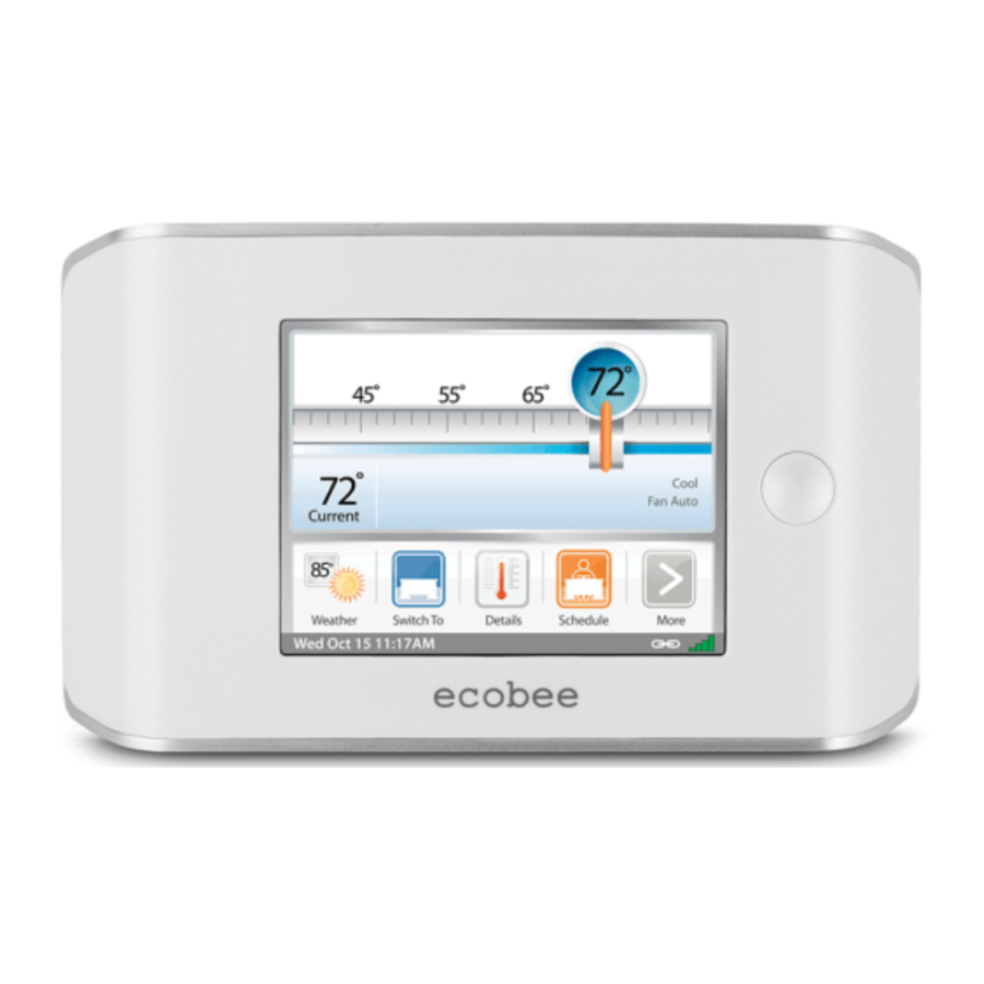
What's on the Home Screen?
The Home Screen displays the current temperature, various heating and cooling settings, and icons for navigating to other features and settings of the Thermostat. The Home Screen is the default display for the Thermostat

- Set Temperature
The set temperature is the temperature the system is programmed to maintain. - Set Temperature Adjustment Slider
Using your finger, drag the slider back and forth to manually lower or raise the set temperature. Tapping at either end of the temperature scale will move the slider by 1°F (0.5°C). When you manually adjust the set temperature you will put the system into a Hold mode.
If the system is enabled for Auto change-over mode, and you have selected Auto, an arrow will be displayed on the temperature scale in addition to the magnifier.
This will allow you to adjust both the heating and cooling set temperatures. Pressing the arrow will switch the magnifier to that location and allow you to change that temperature.
There is a minimum difference allowed between the heat set temperature and the cool set temperature. If you change the temperatures and this minimum is not maintained, the system will automatically adjust the other set temperature to compensate. These features are configurable in the Installation Settings. - Current Temperature
This is the current temperature in the room where the Thermostat is installed. The Thermostat sends signals to the heating and cooling system to make sure this temperature matches the set temperature on the Thermostat. - System and Fan Settings
Displays the current operating mode of the heating and cooling system, as well as the furnace fan setting. Press Details to adjust these settings. - System Messages
Provides additional information on the operation of the system. - WiFi Signal Strength Indicator
Indicates the strength of the signal the Thermostat is receiving from the WiFi router. You must have WiFi enabled for the indicator to work. - Current Date and Time
Displays the current date and time. - Internet Connection Indicator
Indicates that the Thermostat is connected to the Internet.
Feature Icons
The feature icons allow you to quickly access the various features of the ecobee EMS. Press any one of these icons to activate that specific feature.
 | Register Use the Register icon to initiate the registration process. This will prompt you to configure the WiFi radio. For the EMS system to complete the registration process you will need to log into the ecobee EMS Web portal and enter the Thermostat's 12-digit serial number. Once successfully registered, the Registration icon is replaced by the Weather icon. |
 | Weather The Weather icon displays the current outdoor temperature for the specific Thermostat location that was entered during the registration process. Press the icon to see the full five-day forecast. |
 | Detail Press the Details icon to see system details such as humidity levels and furnace fan settings. If you have a ventilator, humidifier or dehumidifier connected, Details will also display these settings. |
 | Program Press Program to set the desired temperatures throughout the day for each day of the week. The image on this icon will change to show which period of the day (Occupied, or Unoccupied) is currently in effect. |
 | Resume If the Thermostat has been manually adjusted, the Resume button will be displayed. Pressing this button will cause the system to revert back to the scheduled program |
 | Switch To Pressing the Switch To icon will switch the system to the period shown in the icon. If the system is in the Unoccupied period, it will switch to the Occupied period and remain there for 2 hours. If the system is in the Occupied period, it will switch to the Unoccupied period and remain there until the next scheduled transition. |
 | More Press this icon to navigate to additional features. |
Cleaning the Touch Screen
Press the Clean me icon to deactivate the touch screen. You can clean the Thermostat touch screen by spraying water or any mild, non-abrasive household cleaner on a clean cloth. Wipe the surface of the touch screen with the dampened cloth.
To clean the touch screen:
From the Home screen, press More.

Press Clean Me.

Note: Do not spray any liquids directly onto the Thermostat.
The touch screen will be deactivated for 20 seconds and the time to reactivation will count down.
Viewing Details
The Details screen lists various temperature and equipment details associated with the Thermostat:
To access your Details:
From the Home screen, press Details.

Current Temperature
The temperature in the room where the Thermostat is installed.

System Mode
Displays the mode the system is operating in. Press this item to display a list of options:
- Cool The system will turn on the air conditioner when the current temperature rises above the set temperature.
- Heat The system will turn on the furnace when the current temperature drops below the set temperature.
- Auxiliary Heat Only The system will only use the auxiliary or back-up heat source to maintain the heat set point temperature
- Auto The system is in Auto change-over mode and will activate the heating or cooling systems to keep the building within the desired range of set temperatures. This option is only available if enabled in the Installation Settings.
- Off The system is off and will only display the current temperature.

Fan Control
Displays the current furnace fan setting. Press this item to toggle between:
- On The fan runs all the time regardless of programming, or if there is a call for heat or cool. The fan will also run if the System Mode is Off.
- Auto Turns on the furnace fan when the system is heating, cooling or ventilating the building, or to satisfy the minimum fan "on" time.
When you switch between Auto and ON in fan control, the Thermostat will prompt you with the following:
Hold 2 hours
Hold 4 hours
Indefinite The fan will switch to this setting and will only revert back if you do so manually - Minimum "On" Time This feature allows you to determine a minimum time per hour that the furnace fan will run. This results in optimal air circulation and a more consistent temperature within the building, and is more cost-effective than choosing the On setting.

Current Humidity
Displays the current percentage of humidity in the room where the Thermostat is installed. Humidity displays even if the Thermostat has not been configured to control a humidifier or dehumidifier.
Humidifier | Dehumidifier
Humidity is an important factor in the overall comfort.
If the Thermostat was configured to control a humidifier or dehumidifier, you will be able to select the options below to control the level of humidity in the building.
Humidifier
This option will let you configure the humidifier connected to the Thermostat. Options are:
- On The system will maintain the humidifier to the programmed level.
- Off The system will not control the humidity in the building.
Frost Control
During the heating season, the Thermostat will automatically adjust the humidity levels to minimize frost or condensation forming on the windows. Internet access is required for this feature to operate properly.
Humidifier Set Point
Select this option to program the desired set point for the humidifier. If Frost Control is selected, this option will display the optimal level.
Dehumidifier
This allows you to turn the dehumidifier on or off.
Dehumidifier level
Select this option to program the desired set point for the dehumidifier.

Ventilator Max
If the system is equipped with a ventilation system, you can manually switch the ventilator to the maximum setting directly from the Thermostat.
When you select this, the ventilator switches into the maximum mode for 20 minutes then switches back to its normal operating state. The system fan is also activated.
Viewing Sensor
optional EB-RSM
If you have the optional remote sensor module installed, when you press the More icon from the home screen a new sensor icon will be displayed. This feature will allow you to view the readings of all the sensors connected.
In addition for any of the sensor configured as a control sensor, you will be able to select which temperature or sensors will be used as the set temperature. If more than one is chosen the Thermostat will take the average of those sensors. The same logic applies for indoor humidity sensors.
Preferences and Settings
Once you have connected to the Internet, the following steps can be done either at the Thermostat or with through the EMS Web Portal. The steps below indicate how to perform these functions from the Thermostat.
Temperature Display
Touch the Temperature Display to select Fahrenheit (°F) or Celsius (°C).
To set up Preferences:
From the Home screen, Press More.

Press Settings and select Preferences.

Date and Time
Touch Date & Time to:
- Set the current date
- Set the current time
- Select between 12-hour or 24-hour time format
- Select the time zone where the Thermostat is located
- Enable or disable daylight savings adjustments.
Program the time and date as well as the time zone. If the Thermostat is connected to the Internet, time and date are programmed automatically.
The time zone determines when the system needs to adjust for daylight savings time.
Sound Effects
The Thermostat can make sounds when you press a button or when an alert is generated. Press Sound Effects to:
- Turn on/off the sound when a button is pressed
- Adjust the volume of the sound when a button is pressed
- Turn on /off the sound when an alert is generated
- Adjust the volume of the sound for an alert
Brightness
The touch screen display has adjustable backlight brightness. You can control the intensity when the screen is active and when the display is in standby mode. Press Brightness to:
- Set the Active brightness intensity
- Set the Standby brightness intensity
- Set the minimum time the Thermostat will stay in active brightness before switching to Standby brightness
Holding Action
Whenever you manually adjust the set temperature, the Thermostat will indicate you are "holding." You can select how long the Thermostat will hold the new temperature before reverting back to the regular program. The options are:
- 2 hours
- 4 hours
- Until Next Transition The temperature will be held until the next program stage
- Indefinite The Thermostat will continue to hold at this temperature until you press the Resume button located at the bottom of the home screen.
- Update Program When you adjust the set temperature, the system will reprogram the temperature for the program period you are currently in.
- Ask Me Every time you adjust the set temperature you will be asked which of the options you would like to choose.
Access Control
You can configure the Thermostat so certain features will require the user to enter a 4-digit access code. To enable the access code, enter a 4-digit number. (To disable this feature simply delete the number.)
You can also configure the level of access control.
Restrict All Access
Unauthorized users will only be able to view the home screen and the weather information.
Restrict Details Access
The code is required to access the Details screen.
Restrict Program Access
The code is required to view and modify the Thermostat's program.
Restrict Calendar Event Access
The code is required to view and create a Calendar Event.
Restrict QuickSave
The security code is required to both enter and exit QuickSave mode. QuickSave is only used when the Thermostat is in Vacation Property mode.
In all cases once the code is enabled, it will be required to access any of the list items in the Settings menu, with the exception of the About screen.
Note: Once an access code is entered, the Thermostat will allow access until the Backlight timer reverts to standby mode. If no standby mode is selected, the access code will expire 2 minutes after it was entered.
Temperature Range
You can configure the Thermostat so that only a specific heat and/or cool set point range is permitted.
Heat Temp Range
Users will not be able to set the Thermostat to a temperature above this limit.
Cool Temp Range
Users will not be able to set the Thermostat to a temperature below this limit.
Recovery Options
Recovery options allow the EMS to learn how the heating and cooling system works, taking into account infrastructure, weather and historical performance, to efficiently recover from temperature set back or set forward.
Smart Recovery Heat
The EMS will start recovery at the optimum time to ensure the set point is reached at the programmed time.
Smart Recovery Cool
The EMS will start recovery at the optimum time to ensure the set point is reached at the programmed time.
Random Start Heat
Programming a time in this section will produce a random delay when there is call for heat. In applications with multiple heating systems, this prevents all systems from activating at the same time, creating a peak power demand.
Random Start Cool
Programming a time in this section will produce a random delay when there is call for cooling. In applications with multiple cooling systems, this prevents all systems from activating at the same time, creating a peak power demand.
Economizer Setting
If a relay output is configured as an Economizer output, the following options will be made available:
Disable Economizer during Smart Recovery
If enabled, the Economizer relay output will not activate during Smart Recovery for heat or cool. It will only activate when the system is in an Occupied period.
If No is selected, the Economizer output will activate during the recovery from the Unoccupied to Occupied periods.
Perform Pre-occupancy Purge
If enabled, the Pre-occupancy Purge will be activated a minimum of 1 hour before the transition to an Occupied period.
Device Name
This section allows you to program a name (i.e. Front Office) on the Thermostat. This is useful if you have multiple systems or zones. You can view the Thermostat name in the About menu on the Thermostat and also in your online Web Portal.
Notes
This section allows you to program information you would like the user or service contractors to know about the equipment. For example, which roof-top unit the Thermostat is controlling or where the Equipment Interface is installed.
To view Notes:
From the Home screen, press More.

Press Settings and select the About Menu.

Vacation Property
This option puts the ecobee EMS in a mode suitable for vacation rental properties. With this option enabled, the Thermostat will normally be programmed to remain in the unoccupied state (i.e., the property is vacant). The property manager can then schedule a calendar event that coincides with rental periods. During this calendar event, the ecobee EMS will switch to the occupied state but look and feel like the residential ecobee Smart Thermostat. The renters will have access to features like QuickSave, manual adjustments and hold settings (still within the limits as programmed). Once the calendar event (i.e., rental period) has elapsed, the Thermostat will automatically revert back to the unoccupied state.
Programming the Device
The ecobee EMS is flexible enough to handle the most demanding schedules. Multiple Occupied or Unoccupied periods can be programmed on a daily basis. If a different time or set temperature is required, a Custom Period can also be programmed.

Occupied
Represents the period when the building or area is occupied. When this period is active, any relay programmed as Economizer or Occupied will be activated.

Unoccupied
Represents the period when the building or area is unoccupied. When this period is active, any relay programmed as Economizer or Occupied will not be activated.
Custom Period
Custom Period allows you to assign a name and whether the period is occupied and unoccupied. You can then customize the EMS with set temperatures and times that are different than the standard periods. For example, if you have an occupied period on the weekend, but do not require the set temperature to be as high/low as during the week, you would create a custom period called Weekend. Configure it as an occupied period and program unique set temperatures, then assign this new period to the days that are applicable. See the Using the Editor section on how to Add Custom periods.
There are three ways to program the schedule for the ecobee EMS: Use the Wizard to guide you through the steps, use the more advanced Editor feature OR program multiple Thermostats remotely using the EMS Web Portal.
Using the Program Wizard

The Thermostat Wizard takes you through a step-bystep process to set the program schedule.
If you want to change anything, you can either run the Wizard again, or press Editor to make specific changes. See Using the Editor.
Note: If the Thermostat is in Hold mode, you must press Resume in order to get to the wizard.
If you do not immediately connect to the Internet, you must ensure the time and date are programmed. Refer to Preferences and Settings for details.
Note: Humidity levels are not included as a programmable option, even if a humidifier or dehumidifier is installed and controlled by the Thermostat.
To use the Wizard:
From the Home screen, press Program.
Press Wizard in the upper right corner of the screen
Choose the setting that best fits your daily routine.

Press Next to go to the next question.

When the Congratulations screen appears, press Done.

Using the Editor

The Editor is a more advanced feature that allows you to edit specific times, temperatures and furnace fan settings for each day of the week, add additional Occupied or Unoccupied periods throughout the day or week as well as create customized periods.
You can select the desired program period to adjust start times or disable the period entirely.
Select a current Heat or Cool set temperature to adjust the temperature or fan settings for that period. Any program period changes will automatically apply to all the days that period runs and are shown at the top of the screen.
If the system is enabled for Auto change-over mode, the heat and cool set temperature will automatically be adjusted to ensure a minimum difference is maintained. Auto change-over mode and the minimum temperature difference are configurable in the installer setting.
Note: In Auto change-over mode the fan setting will revert to whatever is configured in the Details.
To use the Editor:
From the Home screen, press Program, then press Editor in the upper left corner of the screen.

Select the days you want to adjust (choosing more than one day will change settings for all the days selected), and press Next.

Adjust temperature by pressing the heat or cool buttons on the right-hand side. OR select Add new item to add a custom period.
Add a new Item
Select this option to add a new Occupied, Unoccupied or custom period to the selected day(s).
Scheduling a Calendar Event
The Thermostat's Calendar Event feature helps conserve energy while the building is unoccupied for long periods of time and also ensures that the building is comfortable when it is occupied.
You can enter any number of uniquely named Calendar Events. Other features to choose from include:
To schedule a Calendar Event:
From the Home screen, press More.

Press Calendar Events. Press New and enter a name and the duration of your Event.

ecobee Optimize
Turn this option ON and the EMS will automatically set the heat temperature, cool temperature, system mode and furnace fan settings to maximize energy conservation while the building or area is Unoccupied.
Turn this option OFF to manually configure Heat Temperature, Cool Temperature and Fan settings while the building or area is Unoccupied.
Is Occupied
Select Yes, if during the calendar event the building or area will be occupied. This ensures the economizer or other Occupancy relays are properly activated.
Heat Temperature
Programs the set temperature when the system is in Heat mode (i.e., when the furnace is on). Set a lower temperature to conserve energy.
Cool Temperature
Programs the set temperature when the system is in Cool mode (i.e., when the air conditioner is on). Set a higher temperature to conserve energy.
Fan
Toggles the fan setting between ON and Auto.
- ON The fan runs all the time regardless of programming or if there is a call for heat or cool. The fan will also run if the System Mode is OFF.
- Auto This option turns the furnace fan on but only when the system is heating, cooling or ventilating the building, or to satisfy the minimum fan run time as programmed.
- Minimum On Time This feature allows you to determine a minimum time per hour that the furnace fan will run. It results in increased air circulation and a more consistent temperature within the home, and is more cost effective than choosing the ON position for the fan.
In either mode, the system will ensure that when the Calendar Event ends the Thermostat will revert to the regular settings.
Note: If you were running the regular program prior to the start of the Calendar Event, on your return the ecobee EMS system will restore the building to those settings. If you were in Hold mode prior to the start of the Calendar Event, the system will restore the building to whatever the set temperature was just prior to the Calendar Event.
Performing a Hardware Reset
In rare circumstances, static electricity or power surges may interrupt the operation of the Thermostat or Equipment Interface, forcing a hardware reset.
Resetting the Thermostat
You can reset the Thermostat by pressing the hardware reset button, located through an opening in the top left corner of the Thermostat, as shown below. Pressing the hardware reset button will not alter programming or configuration options.

Reset button indicated in solid color
©2010 ecobee
333 Adelaide Street West | 6th Floor
Toronto | Ontario | M5V 1R5 | Canada
toll free 1.877.932.6233
www.ecobee.com
MA-EMS-201-R2

Documents / Resources
References
Download manual
Here you can download full pdf version of manual, it may contain additional safety instructions, warranty information, FCC rules, etc.
Advertisement


Need help?
Do you have a question about the EMS and is the answer not in the manual?
Questions and answers