Garmin Apollo SL40 User Manual
Vhf comm
Hide thumbs
Also See for Apollo SL40:
- Installation manual (38 pages) ,
- Pilot's manual (22 pages) ,
- User manual (22 pages)
Table of Contents
Advertisement
Advertisement
Table of Contents

Related Manuals for Garmin Apollo SL40


Summary of Contents for Garmin Apollo SL40
- Page 2 No part of this document may be reproduced in any form or by any means without the express written consent of Garmin AT, Inc. II Morrow, Garmin AT, and Apollo are trademarks of Garmin AT, Inc. © 2003 by Garmin AT, Inc. All rights reserved.
-
Page 3: Welcome
Our products are built to last and to allow for upgrading as your needs change in the future. The SL40 is also packaged in configurations to meet the needs of customers for base station and mobile applications. Contact the Garmin AT factory for more... -
Page 4: History Of Revisions
History of Revisions December 1996 Original Release March 1997 Rev. -01 June 1998 Rev. -02 September 2003 Rev. -02a Ordering Information To receive additional copies of the Apollo SL40 User’s Guide, order part #560-0954-02a. The Apollo SL40 Installation Guide is part #560-0956-xx. -
Page 5: Table Of Contents
Table of Contents Welcome ... · · · · · · · · · · · · · · · · · · · · · · · i History of Revisions · · · · · · · · · · · · · · · · · · ii Ordering Information ·... - Page 6 Display Brightness · · · · · · · · · · · · · · · · 13 SL40 Specifications · · · · · · · · · · · · · · · · · 14 Features· · · · · · · · · · · · · · · · · · · · · · 14 Performance ·...
-
Page 7: Introduction
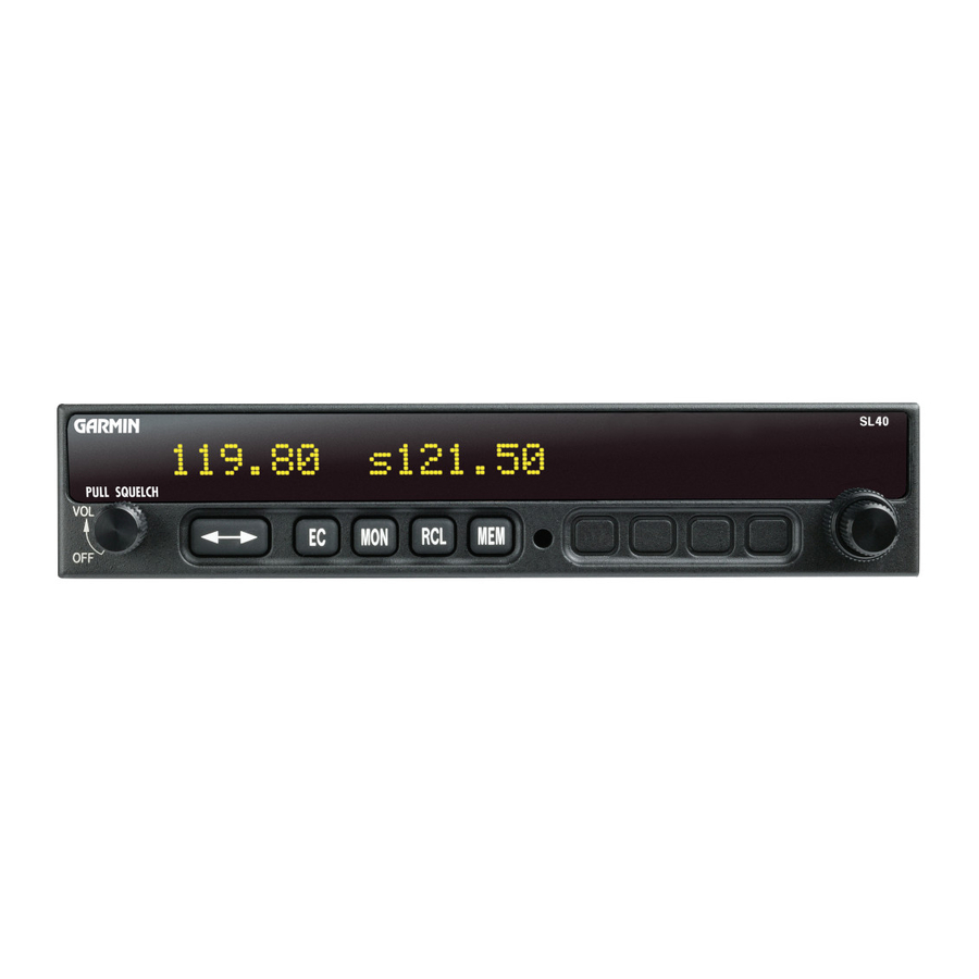
(Transmit) annunciator is lighted whenever you are transmitting. If the avionics bus drops below 9 VDC, the SL40 will not transmit. An LED will be lighted above the MON and RCL buttons when these functions are selected. An “s” will appear to the left of the Standby frequency. -
Page 8: Controls
Power/Volume/Squelch Controls The knob on the left side of the SL40 controls power PULL SQUELCH on/off, volume, and squelch test. Rotate the knob clockwise (CW) past the detent to turn the power on. Continuing to rotate the knob to the right increases speaker and headphone amplifier volume level. -
Page 9: Basic Operation
Frequencies frequency and then toggled to the Active side when desired. While viewing the frequency display, use the Large and Small knobs on the right side of the SL40 to select the desired frequency. 119.80 1. Turn the Large, outer knob to change the values in 1 MHz increments. -
Page 10: Frequency Monitoring
Apollo GPS receiver and a list has been received Remote (REM) The Remote function will allow the SL40 to access the airport frequency database in an Apollo GPS receiver. Press RCL to view the Remote (REM) frequencies. Then, turn the Small, inner knob to display the available frequencies. -
Page 11: Auto Stack List (Lst)
User Stored Frequencies (MEM) When you press the MEM button the Standby frequency is stored in User memory. The SL40 stores the last eight frequencies selected by the user. After eight User frequencies are stored, you will be prompted that the stack is full (mem full). -
Page 12: Weather (Wth)
Basic Operation Weather (WTH) The standard weather channels are stored in the memory of the SL40. You cannot transmit on a weather channel frequency. A small “x” to the right of the Active frequency indicates that transmitting is not permitted. -
Page 13: Removing A Frequency From User Memory
Basic Operation Removing a Frequency from User Memory You may edit the contents of User memory to remove its stored frequencies when you want to make a change or you receive a “MEM Full” message. 1. Press RCL. Turn the Large knob to the User (MEM) frequencies. -
Page 14: Assigning An Id To A User Frequency
Basic Operation Assigning an ID to a User Frequency Frequencies in User (MEM) memory can be given an alphanumeric identifier for your ease of use. 1. Press RCL. Turn the Large knob to the User (MEM) frequencies. 2. Press MEM and hold it for about two seconds. -
Page 15: Intercom Function
Basic Operation When two headphone and microphone jacks are Intercom Function connected to the SL40, these headsets can be used as a voice-activated intercom. When you select the Intercom function with the installed selector switch, the intercom function is enabled. The Volume control will control the headphone listening level. -
Page 16: System Functions
System Functions System Functions The SL40 includes a number of System Functions that give you more information about your communication equipment. Press and hold the MON button for about three seconds to reach the System Function. Turn the Large, outer knob to display the available functions. -
Page 17: Rf Level
System Functions The RF Level function shows the relative signal strength RF Level of the frequency you are listening to. The range displayed is between 0 and 255. The value will constantly change as you are viewing it as signal conditions change. -
Page 18: Mic Squelch 1 And 2
System Functions The input level required to break squelch by the Mic Squelch 1 and 2 microphone is set from this page. Lower numbers indicate a higher input level necessary to break squelch. Turn the Small knob to change the value. The range is from 0 to 127. -
Page 19: Sidetone Level
0 to 255. Setting the value to 0 slaves the sidetone level to the volume control knob. Sidton Lvl As it arrives from the factory, the SL40 automatically Display Brightness adjusts its display brightness for the current lighting conditions. -
Page 20: Sl40 Specifications
SL40 Specifications SL40 Specifications Features 760 Communication Channels Frequency Range: 118 to 136.975 MHz Active and Standby Flip/Flop Frequencies Volume Control 16-Character High-Intensity Alphanumeric LED Display Automatic Display Intensity Control Backlit Keypad Controls Transmit Status Indicator 2x8 Frequency Memory and Recall... -
Page 21: Physical
SL40 Specifications Physical 1.3” (H) x 6.25” (W) x 10.5” (D) Weight: 2 lbs... - Page 22 SL40 Specifications Notes...
- Page 24 © 2003 by Garmin AT, Inc. 2345 Turner Rd., S.E. Salem, OR 97302 U.S.A. Phone 503.581.8101 800.525.6726 In Canada 800.654.3415 FAX 503.364.2138 http://www.garminat.com Part #560-0954-02 Rev A September 2003...
Need help?
Do you have a question about the Apollo SL40 and is the answer not in the manual?
Questions and answers