Garmin Apollo SL40 Installation Manual
Garmin installation manual vhf comm transceiver sl40
Hide thumbs
Also See for Apollo SL40:
- Installation manual (38 pages) ,
- User manual (24 pages) ,
- Pilot's manual (22 pages)

Related Manuals for Garmin Apollo SL40


Summary of Contents for Garmin Apollo SL40
- Page 1 £ Apollo Model SL40 VHF COMM Transceiver Installation Manual September 2003 560-0956-03a...
- Page 2 No part of this document may be transmitted, reproduced, or copied in any form or by any means without the prior written consent of Garmin AT, Inc. Due to Garmin AT, Inc.’s commitment to constantly improve the quality and performance of our products, information contained in this document is subject to change without notice.
-
Page 3: History Of Revisions
The article may be installed only if further evaluation by the user/installer documents an acceptable installation and is approved by the Administrator.” RDERING NFORMATION To receive additional copies of this publication, order part # 560-0956-03a, Apollo SL40 VHF COMM Installation Manual. Description Initial release. - Page 4 OTES...
-
Page 5: Table Of Contents
SECTION 4 - LIMITATIONS ... 19 ... 19 NSTALLATION ... 19 PERATIONAL APPENDIX A - TROUBLESHOOTING... 21 ONTACTING THE ACTORY FOR Apollo SL40 Installation Manual ... 4 ... 5 ... 5 ... 5 ... 7 ... 8 ONNECTIONS ... 12 ... - Page 6 IGURE ONNECTOR 5 SL40 S IGURE TANDALONE 6 SL40 T IGURE YPICAL UDIO ... 16 IGURE IMENSIONS ... 3 ... 21 UIDE ... 6 SSEMBLY ... 9 SSEMBLY ... 10 IRING IAGRAM ... 11 ANEL ONNECTIONS Apollo SL40 Installation Manual...
-
Page 7: Section 1 - Introduction
SL40 D POLLO ESCRIPTION The Apollo SL40 is a 760 channel VHF Comm transceiver. It is one member of the Apollo slimline series, which includes the SL40 Comm, the SL50 GPS, and the SL60 GPS/Comm. EATURES The features of the SL40 Comm include: x 760 channels x Frequency range of 118.000 to 136.975MHz... -
Page 8: Regulatory Compliance
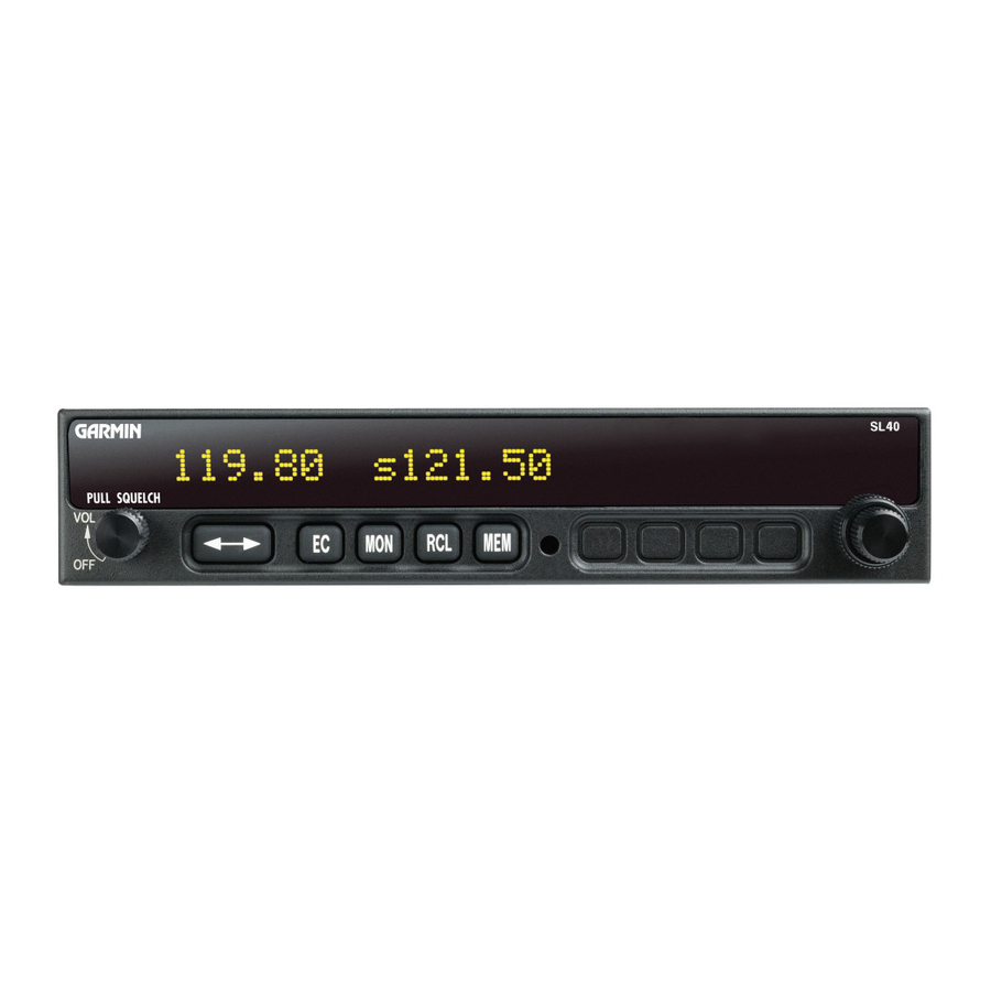
12 watt audio amplifier Figure 1 SL40 Front Panel EGULATORY OMPLIANCE The Apollo SL40 is designed and tested to meet the following TSOs: FAA TSO-C37d for transmit FAA TSO-C38d for receive FAA TSO-C128 for unintentional transmission (stuck mic) The Apollo SL40 complies with the FCC requirements specified in:... -
Page 9: Npacking The Quipment
The Apollo SL40 meets the additional standards as detailed in the Declaration of Conformity included on page 31. Note: Unauthorized changes or modifications to the SL40 may void the compliance to required regulatory agencies and authorization for continued equipment usage. -
Page 10: Other Required Materials
The SL40 is intended for use with standard aviation accessories. The following items are required for the installation: x comm antenna with cables x a microphone x a speaker or headphone These items may be installed dedicated to the SL40 comm or by connections to an audio panel. PECIAL OOLS EQUIRED... -
Page 11: Section 2 - Installation
OUNTING ONSIDERATIONS The SL40 is designed to mount in the avionics stack in the aircraft instrument panel within easy view and reach of the pilot. The standard package includes a mounting frame for ease of mounting, connections, and service of the unit. Allow an additional one inch clearance to the rear of the mounting frame for connectors and cables. -
Page 12: Figure 2 Mounting Frame Assembly
Figure 2 Mounting Frame Assembly Figure 3 Cable Routing Once the cable assemblies are complete and the connectors are attached to the mounting frame, install the mounting frame assembly in the instrument panel. Be sure to use low profile Apollo SL40 Installation Manual... -
Page 13: Electrical Connections
A wiring diagram is included as Figure 5. OWER The SL40 is internally fused at 7 amps. A separate 5 amp (maximum) circuit breaker or fuse should be installed for downline overload or short circuit protection. Make the power connections to the SL40 using 20 awg wire. -
Page 14: Serial Interface
ERIAL NTERFACE The SL40 includes an RS232 serial port, which can be used for inputting frequency and function control commands and outputting transceiver status. This is an optional connection. When making serial connections to the SL40, use a shielded three conductor cable. Make the RxD, TxD, and ground connections on the 15 pin connector. -
Page 15: A Ssembly
Solder Center Conductor Assembly instructions for right angle connector part #162-1008 Figure 4 Coax Connector Assembly Apollo SL40 Installation Manual - Slide clamp nut over coax. Slit 1/4" (2X) - Strip coax as illustrated. - Cut two 1/4" slits in jacket 180 0.125... -
Page 16: Sl40 Standalone Wiring Diagram
Installation Figure 5 SL40 Standalone Wiring Diagram Apollo SL40 Installation Manual... -
Page 17: Sl40 Typical Audio Panel Connections
Installation Figure 6 SL40 Typical Audio Panel Connections Apollo SL40 Installation Manual... -
Page 18: Post Installation Checkout
26% drop. Interference Check Check the SL40 while operating the other avionics and electrical systems on the aircraft to verify that no significant interference exists, and that the SL40 does not cause significant interference with other systems. Performance should be checked using low, high, and mid band frequencies. - Page 19 4. Press any key to exit the Setup Functions mode. 5. Select an appropriate frequency, key the transmitter, and talk into the microphones to check for the intended operation. Apollo SL40 Installation Manual and M EVEL keys while switching the unit on.
- Page 20 50 nm while maintaining an appropriate altitude and over all normal flight attitudes. Performance should be checked using low, high, and mid band frequencies. Apollo SL40 Installation Manual...
-
Page 21: Section 3 - Specifications
Weight (with mounting frame) ... 2.1 lb. (0.953 kg) NVIRONMENTAL The Apollo SL40 unit is designed and tested to meet appropriate categories of RTCA/DO- 160C. The Environmental Qualification Form is included in Appendix C. Operating temperature ... -20qC to +55qC Storage temperature ... -
Page 22: Receiver Performance
Frequency range ... 118.000 to 136.975 MHz, 760 channels Frequency tolerance... r15ppm from -20qC to +70qC modulation at 1000Hz 100mV input, 15% to 90% modulation 6 watts minimum at 10VDC input (transmit is locked out below 9 volts input) Apollo SL40 Installation Manual... -
Page 23: Intercom Performance
Transmit key ... Input pulled low to ground to enable the transmitter Intercom select... Input pulled low to ground to enable the intercom NTENNA EQUIREMENTS The Apollo SL40 requires an antenna meeting the following specifications. Standard 50: vertically polarized antenna with a VSWR < 2.5:1. ERIAL NTERFACE RS-232 ... -
Page 24: Rear Connector Pinout
RS232 serial data input RS232 signal ground intercom function select, pulled low to turn on the intercom function speaker and headphone ground connection headphone terminal output microphone input #2 Viewed from rear of unit Apollo SL40 Installation Manual... -
Page 25: Section 4 - Limitations
4 - L ECTION IMITATIONS NSTALLATION Installations are to be made in accordance with AC 20-67B or other appropriate FAA approved guidelines. PERATIONAL An aircraft radio station license is required for transmitting. Apollo SL40 Installation Manual Limitations... - Page 26 Limitations OTES Apollo SL40 Installation Manual...
-
Page 27: A Ssistance
The intercom doesn’t function. ONTACTING THE ACTORY FOR If the Apollo SL40 unit fails to operate despite troubleshooting efforts, contact the Garmin AT factory for assistance. Garmin AT, Inc. 2345 Turner Rd. SE Salem, Oregon 97302 Phone (503) 581-8101 or 1-800-525-6726 http://www.garminat.com... - Page 28 Troubleshooting OTES Apollo SL40 Installation Manual...
-
Page 29: Leaning The Front Anel
PPENDIX ERIODIC QUIPMENT ALIBRATION The SL40 design requires very few adjustments or calibration to be made. In fact, there are no internal manual adjustments. EFERENCE SCILLATOR The reference oscillator frequency should be checked approximately every 3 to 5 years to ensure the units transmit frequency is within allowable tolerance. - Page 30 Periodic Maintenance OTES Apollo SL40 Installation Manual...
-
Page 31: Appendix C - Environmental Qualifications
C - E PPENDIX NVIRONMENTAL The Apollo SL40 has been tested to the following environmental categories per procedures defined in RTCA/DO-160C. Nomenclature: SL40 Part No.: 430-6040-200 TSO No.: TSO-C37d, TSO-C38d, and TSO-C128 Conditions Temperature and Altitude In-flight Loss of Cooling... - Page 32 Environmental Qualifications OTES Apollo SL40 Installation Manual...
-
Page 33: Appendixe - Serial Interface Specifications
Set the active frequency to 119.100MHz, normal receive mode. “G” = 119d - 30h = 77h - 30h = 47h, or an ascii “G”; “4” = 100 kHz/25 kHz + 30h = 4 + 30h = 34h, or an ascii “4.” Apollo SL40 Installation Manual Serial Data Specifications... - Page 34 4 = APP, for approach NPUT 8 = CTF, common traffic advisory frequency 9 = DEP, departure : (3Ah) = FSS, flight service station ; (3Bh) = RFS, for remote flight service station < (3Ch) = UNI, for unicom Apollo SL40 Installation Manual...
-
Page 35: Rs-232 Outputs
= frequency in kHz where k = (frequency / 25 kHz) + 30h, with frequency in range of 000 to 975 kHz in 25 kHz steps, or 0 to 39. Apollo SL40 Installation Manual Serial Data Specifications = (3Dh) = MF, mandatory frequency >... - Page 36 This message is used to output the com software version. Message Format $PMRRC03vvvv<chksum><cr> 03... message id vvvv... software version Example Message $PMRRC03010024<cr> The software version is 01.00. This message is output once at power up and by request. Apollo SL40 Installation Manual...
-
Page 37: Declaration Of Conformity
Type of equipment: Product name: Part number: conforms to the following Directives and Standards: Application of Council Directives: Standards: Apollo SL40 Installation Manual Garmin AT, Inc. 2345 Turner Rd. SE Salem, Oregon, 97302 USA VHF Comm transceiver for aircraft Apollo SL40 Comm...
Need help?
Do you have a question about the Apollo SL40 and is the answer not in the manual?
Questions and answers