Table of Contents
Advertisement
Advertisement
Table of Contents
Troubleshooting

Related Manuals for Motorola MSAT-G2


Summary of Contents for Motorola MSAT-G2
-
Page 2: Table Of Contents
MSAT-G2 Technical Specifications ........ -
Page 3: Introduction
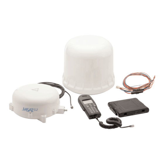
Introduction The purpose of this guide is to provide assistance to personnel installing the new MSAT-G2 mobile satellite radio equipment. The guide starts off by providing installation-specific information on each component of the radio. Installation tips are then offered for fixed-site and vehicular scenarios. - Page 4 Antenna Unit External Speaker External Speaker Antenna Cable Transceiver Unit External Interface Handset Serial Handset Cable 12 power supply Debug/Upgrade/ Ethernet Power Cable Future Expansion Figure 2 – System Overview MSAT-G2 Installation Guide...
-
Page 5: Transceiver Unit (Tu)
The TU provides the interface for the handset and antenna unit (AU) and manages the communications over the MSV network. It also distributes power to the handset and Antenna Unit (AU). FRONT BACK Figure 3 - Transceiver Unit w/o Mounting Bracket MSAT-G2 Installation Guide... -
Page 6: Power Port
The pinout of the port supports a direct straight-through connection to a PC with a standard Ethernet cable. The PC shall be supplied with a dynamic local IP address using a standard DHCP exchange. Figure 5 – Ethernet Port Pinout MSAT-G2 Installation Guide... -
Page 7: Serial Port
Note: Grounding the center conductor while power is applied to the transceiver can cause the transceiver's fuse and/or a fuse in the vehicle to blow. No modifications should be made to the RF cable under any circumstance Figure 7 – Antenna Port Detail MSAT-G2 Installation Guide... -
Page 8: Handset Port
Data TX – TU Send Data RX – TU Receive + 12 VDC Ground Audio RX + Speaker Audio RX - Speaker Figure 8: Handset Connector Pin-out External Speaker A 3.5 mm mono connection is provided for a 4W 8Ohm speaker. MSAT-G2 Installation Guide... -
Page 9: System Power Requirements
12 VDC power supply. Power requirements and consumption are as follows: Voltage Input Minimum 11.5 V DC Voltage Input Maximum 15.6 V DC Total Current for AU,TU & Handset (Max.) Required Fuse Figure 10 – System Power Requirements MSAT-G2 Installation Guide... -
Page 10: Power Cable
AWG 16, STRANDED, RED AWG 20, STRANDED, ORANGE VIEW A HOUSING : MOLEX PART NO. 39-01-2045 TERMINAL: MOLEX PART NO. 44476-3111 (FOR AWG IG WIRE) AND 44476-1111 (FOR 20 WIRE) IN LINE FUSE HOLDER Figure 11 – Power Cable Details MSAT-G2 Installation Guide... -
Page 11: Standard Cable Connections
(ACC) by the end user may lead to a discharged car battery. NOTE: Ensure that the connection is a switched source-OFF when ignition is off or in start and ON only when ignition switch is in ACCESSORIES or RUN position. MSAT-G2 Installation Guide... -
Page 12: Basic Installation Procedure
Basic Installation Procedure While the installation of the MSAT-G2 mobile satellite radio is straightforward, it is essential that the installation be done correctly. The basic installation procedure is as follows: 1. Decide where you are going to install the antenna, TU and handset. -
Page 13: Lightning Arrestors
NOTE: Use care when drilling through the body of the vehicle to avoid puncturing critical items. The bracket is connected to the TU with two (2) provided screws. There is a 5mm gap between the TU and the bracket. MSAT-G2 Installation Guide... - Page 14 TU to the mounting bracket. Not using the supplied bracket screws could result in damage to the TU (especially if screws are too long). MOUNTING HOLE DIMENSIONS BOUNTING BRACKET, MSV Dimensions are in mm Figure 13 - Transceiver Unit Mounting Bracket Dimensions MSAT-G2 Installation Guide...
- Page 15 DIMENSIONS WITH MOUNTING BRACKET MSV TRANSCEIVER UNIT 176.83 33.6 HANDSET SERIAL PORT ETHERNET Dimensions are in mm Figure 14 - Transceiver Unit w/ Mounting Bracket MSAT-G2 Installation Guide...
-
Page 16: The Antenna Unit (Au)
Installing the Antenna WARNING: Avoid exposure to microwave radiation. Keep a safe distance of minimum one 1 meter (39 inches) to the side and above the antenna. Always power the MSAT-G2 down prior to disconnecting or connecting the antenna. The antenna port is a 50 Ohm female TNC. This line carries RF, signaling, and DC power for the antenna. -
Page 17: Spacecom Spac-As-Msv220 Land-Mobile / Fixed-Site Antenna
Do not locate the antenna close to interfering signal sources or receivers. It is recommended that no other antennas be located within three (3) meters of the MSAT-G2 antenna. If there is other equipment installed near the MSAT-G2 satellite radio it is recommended to operate all equipment simultaneously and verify there is no co-interference. - Page 18 “break off”. In some situations the force of the magnet may be too great and it will be necessary to unscrew the antenna first and remove the magnets separately. Hex domed nut M5 washer Rubber washer Rubber washer High “intensity” magnet Figure 17 – SPAC-AS-MSV220 2-axis Antenna W/ Magnetic Mounts MSAT-G2 Installation Guide...
-
Page 19: Permanent (Mast) Mounting
Also be careful with the cable run from the antenna and secure it at short intervals. An unsupported length of cable will vibrate in strong winds and could negatively affect the connection over time. MSAT-G2 Installation Guide... -
Page 20: Spac-As-Msv320 Maritime Antenna
The kit consist of the following components: (subject to change) 1pcs. Mounting Pole, Part No. SPAC-M00424 1pcs. Rubber Gasket, Part No. SPAC-M00425 6pcs. Plastic Bushings, Part No. SPAC-M00227 6pcs. Washer, Part No. SPAC-M90-10062 6pcs. Screw, Part No. SPAC-M90-10102 MSAT-G2 Installation Guide... -
Page 21: Pole Mount Kit Component Description
The centre hole is part of the ventilating system for the dome and MUST NOT BE BLOCKED. The gasket will also protect the TNC-type connector from water and dust. MSAT-G2 Installation Guide... - Page 22 • Protects the co-axial cable going to the antenna and its N-type connector. • Isolates the antenna from the structure on which it is installed, this is a must in maritime installations where no DC current is allowed to flow through any part of the ship. MSAT-G2 Installation Guide...
-
Page 23: Spac-As-Msv320 Antenna Installation
It is, however, the responsibility of the installer to verify that the cited levels are not exceeded in any mode of operation of the vehicle/vessel. In case of abnormal vibration, typically at a resonance frequency, measures much be taken in order to displace the resonance frequency or to dampen the vibration amplitude. MSAT-G2 Installation Guide... - Page 24 U-Clamp SPAC-M00429 U-Clamp (2ONLY). SPAC-M00428 (2 ONLY). Post on vessel Flange SPAC-M00430 (2 ONLY). Screw M5x10 (1 ONLY) Plug for mounting pole Part No.: SPAC- MO0233 (1 0NLY) 35-50MM Figure 21 – SPAC-AS-MSV320 3-axis Antenna Installation Details MSAT-G2 Installation Guide...
-
Page 25: Installing The Handset
Control then reverts to the initial Idle Mode screen. If commissioning is not successful, you will receive a failure message (Network indicates that commissioning has failed, refer to figure 22 – Error Code Diagnostics on the following pages). Contact your Service Provider for assistance. MSAT-G2 Installation Guide... - Page 26 If this message continues, contact the MSAT network. MSV Customer Support. Signifies the PTT key was been pressed Press and hold the PTT key in order PRESSPT then released just before the radio to talk. received the confirmation from the network. MSAT-G2 Installation Guide...
- Page 27 Signifies the user has entered the If you cannot remember the lock WRONG LOCK wrong Handset Lock code. code (default is 0000), enter the CODE SYSTEM password (default 1234) when prompted to enter the code. Figure 22 – Error Codes MSAT-G2 Installation Guide...
-
Page 28: Troubleshooting The Installation
Are the cable connections secure? Are the cables damaged in any way? Is the antenna system damaged? Is the TU damaged? Has any electrical or construction work been done near the TU, antenna or handset? Is the power supply working properly? MSAT-G2 Installation Guide... -
Page 29: Troubleshooting Some Typically Encountered Problems
Check that the account is active and that the unit is in ready to commission status. 3) Signal Strength low/intermittent/none Check the antenna cable connection both at the TU and antenna. Check that the cable is not damaged in any way (pinched, cut etc.). MSAT-G2 Installation Guide... -
Page 30: Msat-G2 Technical Specifications
98% at 100.4°F (38°C) Operating Antenna = -22°F(-30°C) to +109°F(+43°C) Temperature TU = -22°F(-30°C) to +131°F(+55°C) Dust In Accordance with SAE J1455 section 4.7 Rain Antenna = Precipitation rate of 2” /hour Figure 23 – Technical Specifications MSAT-G2 Installation Guide... - Page 31 All trademarks, marks, names, or product names referenced in this publication are the property of their respective owners, and Mobile Satellite Ventures, LP, neither endorses nor otherwise sponsors any such products or services referred to herein. MSV is a trademark of Mobile Satellite Ventures, LP. MSAT-G2 Installation Guide...
Need help?
Do you have a question about the MSAT-G2 and is the answer not in the manual?
Questions and answers