Table of Contents
Advertisement
Quick Links
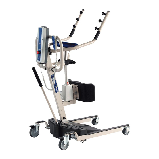
Owner's Operator and Maintenance Manual
Stand Up Lift
Model RPS350-2
DEALER: This manual MUST be given to
the user of the patient lift.
USER: BEFORE using this patient lift, read
this manual and save for future reference.
For more information regarding
Invacare products, parts, and services,
please visit www.invacare.com
Advertisement
Table of Contents

Related Manuals for Invacare RPS350-2


Summary of Contents for Invacare RPS350-2
- Page 1 Model RPS350-2 DEALER: This manual MUST be given to the user of the patient lift. USER: BEFORE using this patient lift, read this manual and save for future reference. For more information regarding Invacare products, parts, and services, please visit www.invacare.com...
- Page 2 EQUIPMENT - OTHERWISE INJURY OR DAMAGE MAY RESULT. INVACARE PRODUCTS ARE SPECIFICALLY DESIGNED AND MANUFACTURED FOR USE IN CONJUNCTION WITH INVACARE ACCESSORIES. ACCESSORIES DESIGNED BY OTHER MANUFACTURERS HAVE NOT BEEN TESTED BY INVACARE AND ARE NOT RECOMMENDED FOR USE WITH INVACARE PRODUCTS. ‘...
-
Page 3: Table Of Contents
Lifting the Patient............................22 Moving the Patient............................24 SECTION 5—TRANSFERRING THE PATIENT ........25 Introduction ...............................25 Transferring to a Commode........................26 Transferring to a Wheelchair ........................27 Transferring to a Bed..........................28 SECTION 6— TROUBLESHOOTING ........... 30 Part No. 1145811 Stand Up Lift Model RPS350-2... - Page 4 3. Receive updates with product information, maintenance tips, and industry news. 4. Invacare can contact you or your provider, if servicing is needed on your product. 5. It will enable Invacare to improve product designs based on your input and needs.
- Page 5 11. User's Year of birth: ______________________________________________________ If at any time you wish not to receive future mailings from us, please contact us at Invacare Corporation, CRM Department, 39400 Taylor Parkway, Elyria, OH 44035, or fax to 877-619-7996 and we will remove you from our mailing list.
- Page 6 Fold here Fold here Invacare Product Registration Form Please Seal with Tape Before Mailing...
-
Page 7: Special Notes
Invacare products are specifically designed and manufactured for use in conjunction with Invacare accessories. Accessories designed by other manufacturers have not been tested by Invacare and are not recommended for use with Invacare products. Part No. 1145811 Stand Up Lift Model RPS350-2... -
Page 8: Specifications
Charger Output/Charging Time 29.5V DC Max 6 hrs Audio Low Battery Alarm Motor Safety Devices Anti-Entrapment *100-200 *Approx. Patient Lifts per Charge Cycles per Charge 1 Year Warranty Electronics Emergency Stop Button *NOTE: Varies depending upon load and stroke. Stand Up Lift Model RPS350-2 Part No. 1145811... -
Page 9: Section 1-General Guidelines
- otherwise, injury or damage may occur. DO NOT move a person suspended in a sling any distance. The Invacare lift is NOT a transport device. It is intended to transfer an individual from one resting surface to another (such as a bed to a wheelchair). -
Page 10: Using The Sling
ALWAYS use the color coded strap on the standing sling closest to the patient while still maintaining patient stability and comfort. Use an Invacare approved sling that is recommended by the individual’s doctor, nurse or medical assistant for the comfort and safety of the individual being lifted. After each laundering (in accordance with instructions on the sling), inspect sling(s) for wear, tears, and loose stitching. Bleached, torn, cut, frayed, or broken slings are unsafe and could result in injury. Discard immediately. DO NOT alter slings. Be sure to check the sling attachments each time the sling is removed and replaced, to ensure that it is properly attached before the patient is removed from a stationary object (bed, chair or commode). If the patient is in a wheelchair, secure the wheel locks in place to prevent the chair from moving forwards or backwards. When connecting slings equipped with color coded straps to the lift, the shortest of the straps must be at the back of patient for support. Using long section will leave little or no support for patientʹs back. The loops of the sling are color coded and can be used to place patient in various positions. The colors make it easy to connect both sides of the sling equally. Make sure that there is sufficient head support when lifting a patient. Stand Up Lift Model RPS350-2 Part No. 1145811... -
Page 11: Lifting/Transferring The Patient
Lifting/Transferring the Patient When using the stand up lift, the legs MUST be in the maximum Opened position before lifting the patient. DO NOT move the patient if the sling is not properly connected to the attachment points of the stand up lift. Check that the sling is properly connected to the attachment points prior to lifting a patient. If any attachments are not properly in place, correct the problem. When the sling is elevated a few inches off the stationary surface and before moving the patient, check again to make sure that all sling attachments are secure. If any attachments are not properly in place, lower the patient back onto the stationary surface and correct this problem ‐ otherwise, injury or damage may occur. Adjustments for safety and comfort should be made before moving the patient. Patientʹs arms should be inside of the straps. Invacare slings are made specifically for use with Invacare lifts. For the safety of the patient, DO NOT intermix slings and lifts of different manufacturers. Warranty will be voided. During transfer, with patient suspended in a sling attached to the lift, DO NOT roll caster base over objects such as carpet, raised carpet bindings, door frames, or any uneven surfaces or obstacles that would create an imbalance of the lift and could cause the lift to tip over. Before positioning the legs of the stand up lift around the patient, make sure the patient’s feet are out of the way of the footplate, otherwise injury can occur. Invacare recommends locking the rear swivel casters ONLY when positioning or removing the sling (standing or transport) from around the patient. Invacare does not recommend locking of the rear casters of the lift when lifting an individual. Doing so could cause the lift to tip and endanger the patient and assistants. Invacare does recommend that the rear casters be left unlocked during lifting procedures to allow the lift to stabilize itself when the patient is initially lifted from a chair, bed or any stationary object. Wheelchair wheel locks MUST be in a locked position before lowering the patient into the wheelchair for transport. Before transferring, check that the wheelchair weight capacity can withstand the patientʹs weight. Part No. 1145811 Stand Up Lift Model RPS350-2... -
Page 12: Performing Maintenance
Refer to Maintenance on page 31 for a maintenance schedule and procedures. Regular maintenance of lifts and accessories is necessary to assure proper operation. After the first year of use, the attachment points and the mounting bracket of the lift arm should be inspected every three months to determine the extent of wear. If these parts become worn, replacement must be made. DO NOT overtighten mounting hardware. This will damage mounting brackets. Casters and axle bolts require inspections every six months to check for tightness, wear, debris (such as hair and dirt) and that they roll free. After the first twelve months of operation, inspect all pivot points and fasteners for wear. If the metal is worn, the parts MUST be replaced. Make this inspection every six months thereafter. Top bolt must be checked at least every six months in conjunction with periodic maintenance. The electric motor is sealed at the factory and if service is required, the motor unit MUST be returned to the factory for repair. DO NOT attempt to open the motor or obtain local service as this will VOID the warranty and may result in damage and a costly repair. Consult your dealer or Invacare for further information. Electrical - Grounding Instructions DO NOT, under any circumstances, cut or remove the round grounding prong from any plug. Some devices are equipped with three‐prong (grounding) plugs for protection against possible shock hazards. Where a two‐prong wall receptacle is encountered, it is the personal responsibility and obligation of the customer to contact a qualified electrician and have the two‐prong receptacle replaced with a properly grounded three‐ prong wall receptacle in accordance with the National Electrical Code. If you must use an extension cord, use only a three‐wire extension cord having the same or higher electrical rating as the device being connected. In addition, Invacare has placed RED/ORANGE WARNING TAGS on some equipment. DO NOT remove these tags. Carefully read battery/battery charger information prior to installing, servicing or operating your lift. Stand Up Lift Model RPS350-2 Part No. 1145811... -
Page 13: Pinch Points
SECTION 1—GENERAL GUIDELINES Pinch Points WARNING Pinch points exist at base of lift. Injury could occur. Pinch Points Base of Lift Part No. 1145811 Stand Up Lift Model RPS350-2... -
Page 14: Section 2- Installation
SECTION 2— INSTALLATION Introduction WARNING Use only Invacare parts in the assembly of this lift. The base legs, mast, and boom assembly and the swivel bar are manufactured to specifications that assure correct alignment of all parts for safe functional operation. -
Page 15: Assembling The Mast Actuator
Otherwise, injury to personnel or damage to lift may occur. A. Turn the lift on its side. B. Position slot in leg actuator over the pivot bracket. C. Install the pin through the leg actuator and pivot bracket and secure with hitch pin. D. Return the lift to the upright position. 3. Perform the following to secure the leg actuator to the mast bracket (Detail “B”): A. Position leg actuator between mast bracket. B. Move the legs to align the holes in the leg actuator with the holes in the mast bracket. C. Install the pin through the holes of the leg actuator and mast bracket and secure with hitch pin. 4. Plug the pendant control into the bottom of the control box. Part No. 1145811 Stand Up Lift Model RPS350-2... - Page 16 DETAIL “A” - SIDE VIEW OF LIFT Bracket Base Hitch Actuator DETAIL “B” Battery Arms Pendant Control Hitch Control Box Mast Bracket Mast Actuator Leg Actuator Mast Slot in Base FIGURE 2.3 Lift Components Stand Up Lift Model RPS350-2 Part No. 1145811...
-
Page 17: Mounting The Battery Charger
4. Install the bottom mounting screw until there is an approximate 1/8‐inch gap between the screw head and the wall. 5. Install the battery charger with mounting bracket onto the bottom mounting screw. 6. Drill the remaining two mounting holes. 7. Install the two remaining mounting screws through the mounting bracket and into the wall. Tighten securely. 8. Plug the battery charger into the wall electrical outlet. 9. Verify that On is illuminated. Mounting Bracket Battery Charger with Mounting Bracket Mounting Screws Bottom Mounting Screw FIGURE 2.4 Mounting the Battery Charger Part No. 1145811 Stand Up Lift Model RPS350-2... -
Page 18: Section 3-Operating The Stand Up Lift
DO NOT lock the rear casters of the stand up lift when lifting an individual. Locking the rear casters could cause the stand up lift to tip and endanger the patient and assistants. NOTE: For this procedure, refer to FIGURE 3.1 on page 19. The pendant is used to raise/lower the stand up lift or to open/close the legs of the base for stability when lifting a patient. Stand Up Lift Model RPS350-2 Part No. 1145811... -
Page 19: Raising/Lowering The Stand Up Lift
FIGURE 3.1 Pendant Buttons Performing an Emergency Stop NOTE: For this procedure, refer to FIGURE 3.2. Press the RED emergency button on the control box to stop the boom assembly and patient from raising or lowering. Rotate the RED emergency stop button clockwise to disengage the emergency stop. Rotate Clockwise to Disengage Emergency Stop Control Box Press IN to Stop Boom FIGURE 3.2 Performing an Emergency Stop Part No. 1145811 Stand Up Lift Model RPS350-2... -
Page 20: Charging The Battery
Otherwise, injury or damage may occur. 3. Place the battery on the battery charger. Make sure there is an audible click. NOTE: The charge LED will illuminate. When charging is complete, charge LED will stop illuminating. NOTE: A battery needing to be fully recharged will take approximately four hours. 4. Lift up on the handle on the back of the battery. 5. Lift the battery up and out of the battery charger. 6. Reinstall the battery onto the control box. Make sure there is an audible click. Handle Audible Click Battery Charger Control Battery NOTE: The battery mounts to the control box and battery charger as shown. FIGURE 3.3 Charging the Battery Stand Up Lift Model RPS350-2 Part No. 1145811... -
Page 21: Section 4-Lifting The Patient
NOTE: For this procedure, refer to FIGURE 4.1. NOTE: Before positioning the legs of the stand up lift, make sure the area is clear of any obstructions. 1. Press the legs open button on the pendant to open the legs of the stand up lift to maximum. Up Arrow Down Arrow Button 2. Position the stand up lift using the mast Button handle. Legs Open Legs Closed Button Button 3. Press the down arrow button on the pendant to lower the lift arms for easy attachment of the sling. FIGURE 4.1 Pendant Buttons Part No. 1145811 Stand Up Lift Model RPS350-2... -
Page 22: Lifting The Patient
Adjustments for safety and comfort should be made before moving the patient. DO NOT use slings and stand up lifts of different manufacturers. Invacare slings are made specifically for use with Invacare stand up lifts. Injury or damage may occur. - Page 23 If transferring from a wheelchair, the wheelchair wheel locks MUST be in the locked position before lowering the patient into the wheelchair. Otherwise, injury may occur. 4. If transferring from a wheelchair, lock the wheel locks on the wheelchair. Refer to Detail “B”. 5. Press the up arrow button to raise the patient above the surface (bed, wheelchair, or commode). The patient’s weight will be fully supported by the stand up lift. Refer to Detail “C”. NOTE: The lower center of gravity provides stability making the patient feel more secure and the lift easier to move. NOTE: The lift arms will stay in position until the down arrow button is pressed. Part No. 1145811 Stand Up Lift Model RPS350-2...
-
Page 24: Moving The Patient
This could cause the lift to tip over. Use the mast handle at all times to push or pull the lift. NOTE: For this procedure, refer to Detail “C” of FIGURE 4.2. 1. Ensure the legs of the stand up lift are in the maximum open position. If not, press the open legs button on the pendant to move the legs to the maximum open position. 2. Move the stand up lift away from the surface. 3. Slowly move the patient to the desired surface. Stand Up Lift Model RPS350-2 Part No. 1145811... -
Page 25: Section 5-Transferring The Patient
Adjustments for safety and comfort should be made before moving the patient. The patient's arms should be inside the straps. DO NOT use slings and stand up lifts of different manufacturers. Invacare slings are made specifically for use with Invacare stand up lifts. Otherwise, injury or damage may occur. -
Page 26: Transferring To A Commode
• Transport Sling ‐ i. Unhook the transport sling from DETAIL “C” - UNHOOKING SLING AND STRAPS the bottom attachment points on the stand up lift. ii. Lift up on the patient’s legs and remove the thigh supports from underneath the patient. iii. If desired, unhook the transport sling from the top attachment points on the stand up lift. NOTE: The patient can remain in the upper portion of the transport sling while using the commode. FIGURE 5.1 Transferring to a Commode Stand Up Lift Model RPS350-2 Part No. 1145811... -
Page 27: Transferring To A Wheelchair
Lock the rear swivel casters ONLY when positioning or removing the sling (standing or transport) from around the patient. Otherwise, injury may occur. 6. Lock the rear swivel casters. 7. Unhook the sling from all attachment points on the stand up lift. Refer to Detail “D”. 8. Instruct patient to lift their feet off the footplate. Assist the patient if necessary. 9. Remove the sling from around the patient. 10. Pull the stand up lift away from the wheelchair. Part No. 1145811 Stand Up Lift Model RPS350-2... -
Page 28: Transferring To A Bed
DETAIL “C” - LOWERING DETAIL “D” - UNHOOKING PATIENT SLING FIGURE 5.2 Transferring the Patient to a Wheelchair Transferring to a Bed NOTE: For this procedure, refer to FIGURE 5.3 on page 29. NOTE: The lower center of gravity provides stability making the patient feel more secure and the lift easier to move. NOTE: The lift arms will stay in position until the down arrow button is pressed. 1. Position the patient as far over the bed as possible. NOTE: If patient is being transferred from a surface that is lower than the bed, press the up arrow button to raise the patient above the surface of the bed. The patient should be elevated just high enough to clear the bed with their weight fully supported by the lift. 2. Press the down arrow button and lower the patient onto the bed. Stand Up Lift Model RPS350-2 Part No. 1145811... - Page 29 TRANSFERRING THE PATIENT WARNING Invacare recommends locking the rear swivel casters ONLY when positioning or removing the sling from around the patient. 3. Lock the rear swivel casters. 4. Unhook the standing or transport sling from all attachment points on the stand up lift. 5. Instruct the patient to lift their feet off of the footplate. NOTE: Assist the patient if necessary. 6. Remove the standing or transport sling from around the patient. 7. Pull the stand up lift away from the bed. DETAIL “A” - LOWERING THE DETAIL “B” - UNHOOKING...
-
Page 30: Section 6- Troubleshooting
15. Contact your dealer. Lift arms will not lower in upper- Lift arms require a minimum Pull down slightly on the lift arms. most position. weight load to lower from the uppermost position. NOTE: If problems are not remedied by the suggested means, please contact your dealer or Invacare. Stand Up Lift Model RPS350-2 Part No. 1145811... -
Page 31: Part No. 1145811 Stand Up Lift Model Rps350-2
Cycle to ensure smooth quiet operation. CLEANING Whenever necessary. SLINGS AND HARDWARE CHECK ALL SLING ATTACHMENTS each time it is used to ensure proper connection and patient safety. Inspect sling material for wear. Inspect straps for wear. Part No. 1145811 Stand Up Lift Model RPS350-2... -
Page 32: Lubricating The Lift
The casters MUST swivel and roll smoothly. A light grease (waterproof auto lubricant) may be applied to the ball bearing swivel of the casters once a year. Apply more frequently if the casters are exposed to extreme moist conditions. Caster Lubricate all pivot points. Wipe all excess lubricant from lift surface. FIGURE 7.1 Lubricating the Lift Detecting Wear and Damage It is important to inspect all stressed parts, such as slings, spreader bar and any pivot for slings for signs of cracking, fraying, deformation or deterioration. Replace any defective parts immediately and ensure that the lift is not used until repairs are made. Cleaning the Sling and the Lift The sling should be washed regularly in water temperature of 180°F (82°C) and a biological solution. A soft cloth, dampened with water and a small amount of mild detergent, is all that is needed to clean the stand up lift. The lift can be cleaned with non‐ abrasive cleaners. Stand Up Lift Model RPS350-2 Part No. 1145811... -
Page 33: Adjusting The Base
FIGURE 7.2 Adjusting the Base Adjusting the Knee Pad Height NOTE: For this procedure, refer to FIGURE 7.3. 1. Pick a height setting that will be comfortable to the patient and provide the necessary support. NOTE: The knee pad should be positioned so that the knee portion of the leg contacts the pad. 2. Using both hands, pull both adjustment pins outward at the same time. 3. Position the knee pad to the desired height and release adjustment pins into the corresponding alignment holes. 4. Check to make sure that both pins are engaged. Knee Pad Adjustment Pin Adjustment Pin FIGURE 7.3 Adjusting the Knee Pad Height Part No. 1145811 Stand Up Lift Model RPS350-2... -
Page 34: Replacing The Knee Pad
Knee Pad Stand Up Lift Washers FIGURE 7.4 Replacing the Knee Pad Replacing the Padded Cover NOTE: For this procedure, refer to FIGURE 7.5. 1. Pull fastening strips on the existing padded cover apart. 2. Remove the existing padded cover from the lift arm. 3. Position the new padded cover around the lift arm. 4. Secure fastening strips on the new padded cover together. FIGURE 7.5 Replacing the Padded Cover Stand Up Lift Model RPS350-2 Part No. 1145811... -
Page 35: Replacing The Mast Actuator
2. Rest the lift arm on your shoulder and remove the top nut, bolt, bracket and bushing from the lift arm mounting bracket. 3. Remove the mast actuator. 4. Reverse the above steps for installation of the new mast actuator. Top Nut Bracket Lift Arm Mounting Bracket Top Bolt Bushing Mast Actuator Bottom Nut Shoulder Bolt Washer Mast Mounting Bracket FIGURE 7.6 Replacing the Mast Actuator Part No. 1145811 Stand Up Lift Model RPS350-2... -
Page 36: Replacing Casters/Forks
NOTE: For this procedure, refer to FIGURE 7.8. 1. Place the lift on its side. 2. Remove the bolt and locknut that secure the existing front caster assembly to the fork. NOTE: The front caster assembly consists of two casters and a washer in between. NOTE: The washer will fall out from between Base the two casters. NOTE: Washer will be reused. Examine and Fork replace if worn. Locknut 3. Position the new/existing washer between the two new casters. 4. Line up the mounting holes in the new front caster assembly and the fork. Bolt Washer 5. Install the bolt through the fork and the new front caster assembly and tighten securely with the locknut. Front Casters FIGURE 7.8 Replacing Front Casters Stand Up Lift Model RPS350-2 Part No. 1145811... -
Page 37: Replacing Forks
Otherwise, injury to personnel or damage to stand up lift may occur. NOTE: For this procedure, refer to FIGURE 7.7 and FIGURE 7.8 on page 36. 1. Place the stand up lift on its side. 2. Remove the front or rear caster from the lift. Refer to Replacing Casters/Forks on page 36. 3. Unscrew the existing fork from the base. 4. Install the new fork onto the base. 5. Install the front or rear caster onto the stand up lift. Refer to Replacing Casters/Forks on page 36. 6. Stand the stand up lift back up. Part No. 1145811 Stand Up Lift Model RPS350-2... - Page 38 MAINTENANCE NOTES Stand Up Lift Model RPS350-2 Part No. 1145811...
-
Page 39: Limited Warranty
For warranty service, please contact the dealer from whom you purchased your Invacare product. In the event you do not receive satisfactory warranty service, please write directly to Invacare at the address on the back cover, provide dealer’s name, address, date of purchase, indicate nature of the defect. - Page 40 Invacare Corporation Canada One Invacare Way 570 Matheson Blvd E Unit 8 Invacare, the Medallion Design, and Yes, Elyria, Ohio USA Mississauga Ontario you can. are registered trademarks of 44036-2125 L4Z 4G4 Canada Invacare Corporation. 800-333-6900 800-668-5324 © 2007 Invacare Corporation Part No.
Need help?
Do you have a question about the RPS350-2 and is the answer not in the manual?
Questions and answers