Table of Contents
Advertisement
Advertisement
Table of Contents

Related Manuals for BK Precision 1900


Summary of Contents for BK Precision 1900
- Page 1 Model 1900, 1901, 1902 Switching DC Power Supply INSTRUCTION MANUAL...
-
Page 3: Safety Summary
Safety Summary The following safety precautions apply to both operating and maintenance personnel and must be observed during all phases of operation, service, and repair of this instrument. Before applying power, follow the installation instructions and become familiar with the operating instructions for this instrument. - Page 4 WARNINGS AND CAUTIONS WARNING and CAUTION statements, such as the following examples, denote a hazard and appear throughout this manual. Follow all instructions contained in these statements. A WARNING statement calls attention to an operating procedure, practice, or condition, which, if not followed correctly, could result in injury or death to personnel.
- Page 5 Compliance Statements Disposal of Old Electrical & Electronic Equipment (Applicable in the European Union and other European countries with separate collection systems) This product is subject to Directive 2002/96/EC of the European Parliament and the Council of the European Union on waste electrical and electronic equipment (WEEE), and in jurisdictions adopting that Directive, is marked as being put on the market after August 13, 2005, and should not be disposed of as...
-
Page 6: Table Of Contents
Contents Safety Summary ..................1 Introduction ....................5 Controls and Indicators ................6 Front Panel ..................6 Rear Panel ..................7 Operating Instructions ................8 Using the Power Supply ..............9 4.1.1 Connection ................9 4.1.2 Self Test Sequence ..............9 4.1.3 Control Knobs ................ -
Page 7: Introduction
A remote sensing terminal (model 1900 only) is also available for use to compensate for voltage drop across load leads. These features make the 1900 Series suitable for a wide range of applications including production testing, telecommunications, R&D, service, and... -
Page 8: Controls And Indicators
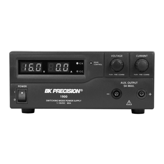
Controls and Indicators Front Panel Figure 1 - Front Panel LED panel meter display with CV/CC indicator Rear Control Indicator (lights up when using Preset/Remote Control/Set mode) Output Voltage Control Knob (control main and auxiliary output voltage) Output Current Control Knob (control main and auxiliary output current limit) Power ON/OFF Switch Auxiliary Output Terminal (max 5 A) 4.1.4 Using Both Main and Auxiliary Outputs... -
Page 9: Rear Panel
Rear Panel Figure 2 - Rear Panel Main Output Terminal (max 60 A for 1900 / 30 A for 1901 / 15 A for 1902) 4.1.4 Using Both Main and Auxiliary Outputs Note: Please see more details on using both main and auxiliary output terminals together. -
Page 10: Operating Instructions
This series has three models with different output voltage and current ranges. Make sure you have purchased the correct one. Model Number Output Voltage Range Total Rated Current 1900 1 – 16 V 0 – 60 A 1901 1 – 32 V 0 –... -
Page 11: Using The Power Supply
Using the Power Supply 4.1.1 Connection To connect the equipment to the power supply, follow the steps below. 1. Check the rating label of the power supply and confirm that it complies with your AC mains voltage. 2. Connect the power supply to the AC mains using the provided power cord and make sure the Mode Selection Switch is in the Normal position. - Page 12 Front Panel Display Test Segment check C.V. indicator check C.C. indicator check Rear control indicator check Return to C.V. Start power supply checks Overvoltage protection check Overload protection check...
-
Page 13: Control Knobs
Front Panel Display Test Overtemperature protection check Fan check Output off (remote control mode) Table 2 - Self Test Sequence The LED and other indicators on the front panel will be turned on. When the cooling fan is being checked, a loud fan noise can be heard. After the self checks, the CV, V, and A LED indicators are lit up displaying voltage and 0.0 current. -
Page 14: Using Both Main And Auxiliary Outputs
For example, setting the voltage and current outputs for model 1900 (1-16 V, 0-60 A) to 16 V and 60 A would output 16 V at both main and auxiliary terminals and allow you to draw up to a total of 60 A between the two terminals. -
Page 15: Normal Mode
The user can also set their own output voltage and current using Set Mode. Please 4.2.3 Set Mode refer to for details. Recall No. Output Voltage Output Current Maximum 13.8 V Maximum Model 1900: 15 V Model 1901: 25 V Maximum Model 1902: 55 V Table 3 - Default Presets... -
Page 16: Set Mode
4.2.3 Set Mode First, enter Set Mode by pushing Mode Selection Switch to “Set” position. To define the preset output P1/P2/P3 1. Select the Recall Switch to the position you want to set: P1, P2, or P3. 2. Adjust the front panel voltage control knob to set your desired voltage value. -
Page 17: Remote Control Mode
Analog Remote Control Connector. Please refer to for more details. Remote Sensing (Model 1900 Only) WARNING: Never short the remote sensing terminal. Never connect the remote sensing terminal in reverse polarity. Always disconnect the remote sensing terminal first after use. -
Page 18: Disconnection
4.3.2 Disconnection WARNING: Wrong disconnect sequence will damage the power supply. 1. Disconnect the remote sensing connections. 2. Disconnect the power connections between the power supply and equipment. Analog Remote Control There are two methods to remote control voltage and current. Note: Both methods require the remote control connector plug to be set up in order for analog remote control mode to be functional;... - Page 19 Figure 5 - Pin Numbers Make sure the load is disconnected and the power supply is OFF. Plug the remote connector plug into the analog remote control terminal of the power supply. Secure the remote connector plug to the terminal socket by locking the Figure 6 connector ring ( Figure 6 - Connector Ring...
- Page 20 Method A: Using Two External Variable DC Voltage Sources FUNCTIONS REMARKS Internal DC +5 V Less than 50 mA Voltage Adjust 0 – 5 V Current Adjust 0 – 5 V Ground Output OFF Short to Ground Table 4 – Remote Connector Plug Pin Assignment for External Variable Voltage Sources A variable external DC voltage source of 0 –...
- Page 21 5. Switch on the power supply. 6. Check the output voltage range of the power supply by varying the external voltage source for voltage adjustment from 0 to 5 V. 7. Short circuit the main output with an 8AWG gauge wire and check the display for CC setting by varying the external voltage source for current adjustment from 0 to 5 V.
-
Page 22: Enable And Disable The Output
FUNCTIONS REMARKS Internal DC +5 V Resistor end Voltage Adjust Variable part of resistor Current Adjust Variable part of resistor Ground Resistor end Output OFF Short to Ground Table 5 – Remote Connector Plug Pin Assignment for Variable Resistors 3. Turn the remote control ON/OFF switch to ON position. 4. -
Page 23: Faults And Troubleshooting
Shorting Pin 5 to Pin 4 (ground) will turn the output off. When output is off, the CV and CC LED will flash. The current output voltage and current setting will show on the panel meter. You can also adjust the output by voltage and current control knob to your desired value when output is off. -
Page 24: Otp: Overtemperature Protection
”), protection will be triggered and the output power will be cut off. OVP warning will appear as shown below. Figure 8 - Overvoltage Protection To reset the warning, switch off the unit and remove all connected devices. Switch the unit back on again and it should resume normal operation. If the problem persists, please contact B&K Precision. -
Page 25: Olp: Overload Protection
When you get this warning, switch off the unit and remove all loading. Check your load and output settings and allow the unit to cool down for at least 30 minutes. Check if any of the ventilation is blocked and make sure there is enough clearance around the power supply. - Page 26 If the fuse blows, the CV or CC indicators will not light and the power supply will not operate. The fuse should not normally open unless a problem has developed in the unit. Try to determine and correct the cause of the blown fuse, then replace only with a fuse of the correct rating as listed below.
-
Page 27: Specifications
Specifications Models 1900 1901 1902 Output Variable Output Voltage 1 – 16 V 1 – 32 V 1 – 60 V Variable Output Current 0 – 60 A 0 – 30 A 0 – 15 A Auxiliary Output Current Voltage Regulation Load (0-100% Load) ≤... - Page 28 23 °C ± 5 °C. Specifications are subject to change without notice. *For 230 V version, please request -220V model on order: 1900-220V, 1901-220V, or 1902-220V. For current up-to-date product information, please visit...
-
Page 29: Certification
Certification CE Compliant CE Declaration of Conformity The power supply meets the requirements of 2006/95/EC Low Voltage Directive and 2004/108/EC Electromagnetic Compatibility Directive. Low Voltage Directive EN 60950 EN 61010 Safety requirements for electrical equipment for measurement, control, and laboratory use. EMC Directive EN 55011 EN 55022... -
Page 30: Service Information
Service Information Warranty Service: Please go to the support and service section on our website at www.bkprecision.com to obtain an RMA #. Return the product in the original packaging with proof of purchase to the address below. Clearly state on the RMA the performance problem and return any leads, probes, connectors, and accessories that you are using with the device. -
Page 31: Limited Two-Year Warranty
Limited Two-Year Warranty B&K Precision Corp. warrants to the original purchaser that its products and the component parts thereof will be free from defects in workmanship and materials, for a period of two years from date of purchase. B&K Precision Corp. will, without charge, repair or replace, at its option, defective product or component parts. - Page 32 (Page intentionally left blank)
- Page 33 22820 Savi Ranch Parkway Yorba Linda, CA 92887 www.bkprecision.com © 2013 B&K Precision Corp. Printed in Hong Kong v0 30314...
Need help?
Do you have a question about the 1900 and is the answer not in the manual?
Questions and answers