Table of Contents
Advertisement
Quick Links
Advertisement
Table of Contents

Subscribe to Our Youtube Channel
Related Manuals for Digitus DN-16035


Summary of Contents for Digitus DN-16035
- Page 1 INTERNET PAN & TILT WIRELESS HD IP CAMERA User Manual DN-16035...
-
Page 2: Table Of Contents
Table of Contents Chapter I: Familiar with your Internet IP Camera ..........4 1.1 Package Contents ................4 1.2 Basic Introduction ................5 1.3 Product Highlights ................6 1.4 Familiar with Key Components ............7 1.5 Descriptions for LED Indicators ............13 1.6 Camera Installation ................ - Page 3 2.7.1 Status ..................80 2.7.2 Space Alarm ................81 2.7.3 File Management .................. 83 Chapter III: Using Surveillance Software ............84 3-1 Installing IP Camera Surveillance Software ........84 3-2 Using IP camera surveillance software ..........88 3-3 Configure IP camera surveillance software ........91 3-3-1 Configure cameras ..............
-
Page 4: Chapter I: Familiar With Your Internet Ip Camera
Chapter I: Familiar with your Internet IP Camera 1.1 Package Contents Thank you for purchasing this IP camera! Before you start to use this IP camera, please check the package contents. If anything is missing, please contact the dealer of purchase and return the package to claim for missing contents. -
Page 5: Basic Introduction
1.2 Basic Introduction Thank you for purchasing this Internet IP camera! This IP camera is an ideal product for all kinds of video-surveillance purposes, like home/office safety, kid/pet monitoring, and remote video acquire etc. Unlink conventional close-circuit video camera; you’re not limited to the length of cable! Once this IP camera is connected to Internet, you can receive video from anywhere in the world where Internet access is available. -
Page 6: Product Highlights
1.3 Product Highlights No pre-loaded software required - all you need is a browser like Internet Explorer 6 (and above, with plugin installed). With supplied video surveillance software, you can connect up to 16 video cameras and view images captured by every camera at the same time. ... -
Page 7: Familiar With Key Components
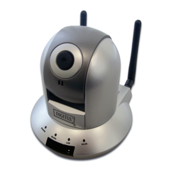
1.4 Familiar with Key Components Front View Focus Ring IR LEDs Microphone Power LED Audio LED LAN LED WLAN LED Wired & Wireless: Power LED Audio LED ACT LED LAN LED POE model: Power LED: Indicates power status Audio LED: Indicates Audio status LAN LED: Indicates LAN activity ACT LED: Indicates Data activity WLAN LED: Indicates Wireless LAN activity... -
Page 8: Antenna
Back View Ethernet Connector Antenna Base (L/R) Power Connector SD Card Slot WPS Button Audio Connector Antenna Base: Connects to supplied antenna Power Connector: Connects to 12V DC power adapter SD Card Slot: Accepts SD / SD-HC memory card for image / video storage WPS Button: click the buttom on IP Cam and click it on the AP you want to connect for wireless Audio Connector: Connects to external speaker for audio output... - Page 9 Back View of Wired model Ethernet Connector Power Connector SD Card Slot USB Port Audio Connector Power Connector: Connects to 12V DC power adapter SD Card Slot: Accepts SD / SD-HC memory card for image / video storage USB Port: Connects to certain wireless module. Audio Connector: Connects to external speaker for audio output Ethernet Connector: Connect to your local area network...
- Page 10 Back View of POE model Ethernet Connector Power Connector SD Card Slot Audio Connector Power Connector: Connects to 12V DC power adapter SD Card Slot: Accepts SD / SD-HC memory card for image / video storage Audio Connector: Connects to external speaker for audio output Ethernet Connector: Connect to your local area network...
-
Page 11: Side View
Side View Reset Button Reset Button: Press the button with pen nib and hold for 5 seconds to reset the camera settings to factory default value. -
Page 12: Bottom View
Bottom View Tripod Connector Tripod Connector: Connects to tripod to secure the camera when the camera is not put on a horizontal surface. -
Page 13: Descriptions For Led Indicators
1.5 Descriptions for LED Indicators Wired and Wireless model LED Name Status Description Power Camera is not powered (camera off) Camera is correctly powered (camera on) LAN port not in use LAN port in use Flash Transferring data via LAN port WLAN Wireless LAN not in use Wireless LAN in use... -
Page 14: Camera Installation
1.6 Camera Installation Please follow the following instructions to set your IP camera up. 1. Unpack the product package and check if anything’s missing. 2. Connect the Ethernet cable to your local area network, and connect the other end to the LAN jack of this IP camera. NOTE: You can skip this step if you plan to use wireless LAN only. - Page 15 3. Plug the power adapter to wall socket, and connect the power connector to the power jack located at the bottom of the IP camera.
- Page 16 4. Connect two antennas to the antenna bases, which is located at the back of this IP camera.
- Page 17 5. Place the camera at a secure place, and point the camera to the place you wish to monitor. If you wish to hang the camera on the ceiling or wall, please use the tripod connector (located at the bottom of the camera) to secure the camera.
-
Page 18: Locate The Ip Address Of This Ip Camera
1.7 Locate the IP Address of this IP Camera Default IP address of this IP camera is 192.168.2.3. If you wish to assign another IP address to this IP camera, you have to log onto the web configuration interface of the camera first. If the left three fields of the IP address of your computer is not 192.168.2, you’ll have to change the IP address of your computer first: 1. - Page 19 2. Double-click ‘Network Connections’ icon. 3. Right-click ‘Local Area Connection’, and click ‘Properties’.
- Page 20 4. Select ‘Internet Protocol (TCP/IP)’, then click ‘Properties’.
- Page 21 5. In ‘IP address’ field, please fill in any IP address begins with ‘192.168.2’, and ends with a value greater than 2 and less than 254 (You can use the example in the picture ‘192.168.2.339’). In Subnet mask field, please fill ‘255.255.255.0’.
-
Page 22: Using Camera Admin Software To Locate Camera
1.8 Using Camera Admin Software to Locate Camera If you can’t connect to the camera by the instructions given in last chapter, you can use camera admin software to search the camera which is connected to your local area network. The admin software is also capable to locate multiple cameras on your local area network. - Page 23 1. Click ‘Next’ to start install camera admin software: 2. You can change the installation folder of camera setup software here, click ‘Browse’ to select an existing folder, or you can just click ‘Next’ to use default installation folder:...
- Page 24 3. If you wish to create desktop icon and / or quick launch icon for camera admin software, please check corresponding box, and click ‘Next’ to continue. 4. You’ll see a brief of all options you selected, click ‘Install’ to install camera admin software now, or click ‘back’...
- Page 25 5. When you see this message, the installation of camera admin software is complete. If you wish to launch camera admin software now, keep ‘Launch IP Cam Admin Utility’ box checked, and click ‘Finish’ to close installation utility. After the camera admin software is launched, all cameras found on your local area network will be displayed:...
- Page 26 All camera-related information will be displayed here. If you wish to connect to certain camera by web browser, double-click the camera listed here. The camera admin software also provides several functions: Language change: This camera admin software supports 3 languages: English, Chinese, and Japanese.
- Page 27 Input the password (default: 1234) and click OK to configure the camera’s network and security setting: In ‘Lan Setting’ page, you can configure camera’s network settings. Select ‘DHCP’ to set the camera to obtain an IP address from DHCP server on local area network automatically, and select ‘Manual IP’...
- Page 28 In ‘Security’ page, you can change the camera’s name and password (user name is always ‘admin’ and cannot be changed). You have to input the same password in both ‘New Password’ and ‘Confirm Password’ field, or you’ll be prompted to input new password again. Click ‘OK’ to save settings or click ‘Cancel’...
- Page 29 1.9 Log Onto Web Management Interface Make sure the IP camera is correctly powered (Power LED is on), and then launch Internet Explorer and type the IP address of the IP camera in address bar of Internet Explorer. You should be prompted to input the user name and password: Default user name is ‘admin’...
- Page 30 If this is the first time you log onto web management interface, you’ll be prompted to install ActiveX Plugin: When you see this message, please click ‘OK’, and click ‘Download the latest ActiveX’ link to download plugin so you can use this camera: Click ‘Run’...
- Page 31 Click ‘Run’ to install plugin: Please click ‘Next’ button to start installation (click ‘Next’ or ‘Install’ when you’re prompted, until installation is complete).
- Page 32 Click ‘Finish’ to complete plugin installation. Now you can go back to web browser, and you should be able to see the image captured by camera (You may need to press F5 or CTRL-R to reload web page).
- Page 33 Note: If you see one of these messages (or both): Your computer may not have the display capability that this IP camera requires, or you don’t have Microsoft DirectX® installed. Please download Microsoft DirectX® from Microsoft’s website (http://www.microsoft.com), and try again. In some cases, your computer is able to display the image from IP camera correctly, but you’ll still see these messages.
- Page 34 Special notes: Because this IP camera has IR coating on its lens, plants will appear as white because of photosynthesis effect, THIS IS NOT MALFUNTION. Plants seen by human’s naked eyes: Plants seen through this IP camera:...
-
Page 35: Chapter Ii: Using Web Management Interface
Chapter II: Using Web Management Interface 2.1 Camera Settings The first menu after you logged onto web management interface is ‘Camera’, and this is the only menu you can see the real-time image from camera. You can always back to this menu by clicking ‘Camera’ on the top of web management interface. - Page 36 The descriptions of every setting in this menu will be given below: Item Description Pan/Tilt Speed Specifies the moving speed when you use pan / tilt function to point the camera to a new direction. Available options are 1 (fastest) to 5 (slowest). Select 1 to move the camera by a faster speed, but you will not be able to control the movement precisely.
- Page 37 Pan / Tilt Control Moves camera to a new direction. Press one of 8 directional buttons to move the camera, and press ‘H’ to move the camera back to ‘home’ (original) position. Preset Points You can set up to 9 preset points of camera position; press the number to move the camera to preset point instantly.
- Page 38 image, you can click this button to set digital zoom: Click ‘Enable’ to enable digital zoom function, then you can drag the slide bar to adjust zoom ratio. You can also use your mouse to drag the zoom area (the green square) to reposition the zoom area.
-
Page 39: Video
2.2 Video You can change video-related settings of this IP camera in ‘Video’ menu. You can access this menu by clicking ‘Video’ on the top of web management interface. There are 5 types of video settings for this IP camera. To set the option of a certain video setting, put mouse cursor on it and its options will appear. -
Page 40: Mjpeg
2.2.1 MJPEG You can adjust video settings when you select ‘MJPEG’ as video type in ‘Camera’ menu. The descriptions of every setting in this menu will be given below: Item Description Video Resolution Changes the resolution of video. Available options are 1280 x 1024, 640 x 480, and 320 x 240. -
Page 41: Mpeg4
2.2.2 MPEG4 You can adjust video settings when you select ‘MPEG4’ as video type in ‘Camera’ menu. The descriptions of every setting in this menu will be given below: Item Description Video Resolution Changes the resolution of video. Available options are 1024 x 768, 640 x 480, and 320 x 240. -
Page 42: H.264
2.2.3 H.264 You can adjust video settings when you select ‘H.264’ as video type in ‘Camera’ menu. The descriptions of every setting in this menu will be given below: Item Description Video Resolution Changes the resolution of video. Available options are 1280 x 1024, 640 x 480, and 320 x 240. -
Page 43: Osd
2.2.4 OSD If you need to display information about this camera, like camera’s name or current date / time, you can use OSD (On-Screen Display) menu: The descriptions of every setting in this menu will be given below: Item Description On-Screen Display Select ‘Enable’... -
Page 44: Night Vision
2.2.5 Night Vision This camera equips with 9 IR LEDs to enhance video quality in the night. You can enable or disable IR LEDs by ‘Night Vision’ menu: The descriptions of every setting in this menu will be given below: Item Description Alaways** turn off IR led... -
Page 45: Pan And Tilt
2.3 Pan and Tilt This IP camera supports pan and tilt function, as you explored in last section. You can also make the camera move automatically in pan and tilt menu by defining a set of pre-defined path. You can access this menu by clicking ‘PTZ’ on the top of web management interface. - Page 46 3. When you move the camera to the position you want, type a name in ‘Position name’ field, and click ‘Set to Point n’ (where ‘n’ is the number of memory slot) button to save the position to selected memory slot. After you set the position, you can recall the position from ‘Camera’...
-
Page 47: Grand Tour
2.3.2 Grand Tour You can make the camera move between many pre-defined positions, and define the time you wish to pause at every position; this is called as ‘Grand Tour’. Before you can use this function, you have to define at least 2 positions in ‘Preset Points’... - Page 49 The descriptions of every setting in this menu will be given below: Item Description Name Input the name of this set of grand tour here. As you may have many sets of grand tour, please give it a meaningful name so you can remember the main purpose of this set. View with Do not visit all positions in this grand tour by order;...
-
Page 50: Network Settings
2.4 Network Settings All network-related settings can be found in this menu, and you have to specify TCP/IP parameters in this menu if you want to change IP address, use PPPoE, Dynamic DNS, and activate UPnP function. You can access this menu by clicking ‘LAN’ on the top of web management interface. -
Page 51: Lan
2.4.1 LAN You can define IP address and select the port number you wish to use here. - Page 52 The descriptions of every setting in this menu will be given below: Item Description Network Type This camera can obtain the IP address from DHCP server automatically (if you have one), or set a fixed IP address. Select ‘DHCP’ to obtain IP address automatically or ‘Static IP Address’...
-
Page 53: Wlan
2.4.2 WLAN The descriptions of every setting in this menu will be given below: Item Description Wireless Select ‘Enable’ to activate wireless network function of Connection this IP camera, select ‘Disable’ to disable it. Network Type Select the network type of wireless connection. Available options are ‘Infrastructure’... - Page 54 You can set to ‘Adhoc’ when you don’t have any wireless access point, but your computer has wireless network card. Set to ‘Infrastructure’ when you have wireless access point, and you have computers with wired network connection. Available Here shows all wireless access points found by this IP Networks camera.
- Page 55 SSID Input the SSID of the wireless access point you wish to connect. It should be less than 32 alphanumerical characters. When you select a wireless access point above, it’s SSID will be filled in this field automatically. However, if the SSID is not displayed (the wireless access point you selected choose to hide it’s SSID), you have to know it’s SSID and input it here, or you will not be able to connect...
-
Page 56: Dynamic Dns
2.4.3 Dynamic DNS If your ISP does not give you a fixed Internet IP address (i.e. the Internet address you’re using when you access the Internet is not always the same – ask your ISP for detailed information), you can use this function to help you locate the IP address of this IP camera when you’re away from home or office. -
Page 57: Upnp
2.4.4 UPnP When UPnP function is activated, all UPnP-compatible computers / network devices will be able to discover this IP camera automatically (only those in the same local network). This function is useful and you don’t have to remember the IP address of this IP camera. - Page 58 Click the message to open ‘My Network Places’, and you’ll see the IP camera: You can double-click the icon to launch Internet Explorer and log onto IP camera’s web management interface directly.
-
Page 59: Loginfree
2.4.5 LoginFree This camera provides a method to let unauthorized users to view the image captured by this camera, which is called as ‘LoginFree’. When you wish to let everyone to view the image captured by this camera, or integrate the image with your own web application, you can use this function: Input the filename here, and click ‘Apply’... -
Page 60: Rtsp
2.4.6 RTSP If you want to watch video captured by this IP camera by your own RTSP (Real Time Streaming Protocol) media player, you can use this function to setup RTSP parameters, so your RTSP-compatible player will be able to receive video data. The descriptions of every setting in this menu will be given below: Item Description... -
Page 61: Motion Detection
2.5 Motion Detection When you wish to use this camera to monitor the activities, motion detection function will be very useful. Camera will detect the motion in captured image, and take a snapshot when motion is detected. So you can use this camera to keep the safety of the belongings you have. -
Page 62: Motion Detection
2.5.1 Motion Detection You can use this menu to setup basic motion detection settings: The descriptions of every setting in this menu will be given below: Item Description Enable Motion Select ‘Enable’ to enable motion detection, and select Detection ‘Disable’ to disable this function. Motion Detection Select the time interval between two motions from Interval... - Page 63 Recording Time Select the duration you wish this camera to record image when a motion is detected from dropdown menu. Available options are 1, 2, 3, 4, and 5 (seconds). Sending File Select the file type that will be saved when a motion is Type detected.
-
Page 64: Motion Region
2.5.2 Motion Region You can define the motion detection region within the image that camera captures, so this camera will ignore motions which are not covered by the motion region setting, and reduce the chances of false alarm. The descriptions of every setting in this menu will be given below: Item Description Region 1 –... - Page 65 Sensitivity Move the slide bar to change the motion detection sensitivity setting: Drag the slide to the right to increase sensitivity (camera will detect minor changes in the image), and drag the slide to the left to decrease sensitivity (camera will only detect major changes in the image).
- Page 66 2.4.3 Email You can define the destination address of E-mail sending and mail server parameters here. The descriptions of every setting in this menu will be given below: Item Description Recipient E-Mail Input the email recipient’s Email address here. Address E-Mail Subject Specify the title of sending email, so you can identify the mail sent from this camera from others quickly.
- Page 67 select ‘Disable’ to disable it. If you don’t know, please refer to the SMTP server you’re using in your Email software (like Outlook, Outlook Express etc.), or ask your network administrator or ISP. User Name Please input the user name of SMTP server here, if your SMTP server requires the use of authentication.
- Page 68 2.4.4 FTP Configuration You can set FTP server’s parameters here. The descriptions of every setting in this menu will be given below: Item Description FTP Server Input the IP address or host name of the FTP server you wish to use here. FTP Port Input the port number of the FTP server you wish to use here.
- Page 69 Passive Mode Select ‘Enable’ to use passive mode to send file, or select ‘Disable’ to not to use passive mode to send file. Some FTP servers require passive mode, if you don’t know, please ask FTP server’s administrator; most of FTP servers will work fine with both modes, but if you found that non-passive mode is not working, you can try to use passive mode.
- Page 70 2.4.5 SD Card Configuration You can define the filename and destination folder when saving a file in SD card. The descriptions of every setting in this menu will be given below: Item Description Enable Cycle Check this box and this camera will automatically erase Recording oldest image file to make rooms for new image files when SD card is full.
-
Page 71: System Info
2.6 System Info You can use this menu to get the operational information of this camera: After you selected ‘System Info.’, a sub-menu will appear. There are 4 sub-menus available here: Detailed descriptions of every setting will be given below. -
Page 72: Camera Information
2.6.1 Camera Information Camera information allows you to set the name and administrator’s password of this camera. The descriptions of every setting in this menu will be given below: Item Description Camera Name Please specify the name of this IP Camera here. This can be used to identify your camera on the network when you have more than one IP camera in the same network. -
Page 73: Date / Time Setting
2.6.2 Date / Time Setting This setting allows you to change the date and time of the real time clock in this IP camera. You can set the time manually, or use network time protocol (NTP) to set the time automatically. The descriptions of every setting in this menu will be given below: Item Description... - Page 74 Time ‘Yes’; otherwise select ‘No’. Synchronize to Click to input current time of your computer to ‘Set Date / PC time Time manually’ field. Click ‘Apply’ to save settings and make the new settings take effect. If you wish to use the date and time setting of the computer which is connecting to the camera, click ‘Synchronize to PC time’...
-
Page 75: Utilities
2.6.3 Utilities This menu allows you to upgrade firmware, clear all settings, reboot the IP camera, and switch LED lights on/off. The descriptions of every setting in this menu will be given below: Item Description Upgrade If you downloaded latest firmware file from our website, Firmware you can click ’Browse’... - Page 76 setting of your computer if the IP address of your computer does not begin with ‘192.168.2’, and subnet mask is not ‘255.255.255.0’, or you’ll not be able to connect to this IP camera again. Reboot Device If you found the IP camera is responding slowly or behaves strange, you can click this button to try to reboot the IP camera, this may help.
-
Page 77: Status
2.6.4 Status This menu provides all information about this IP camera, like firmware version, system uptime, date / time, and network information. -
Page 78: Account
2.7 Account If you wish to allow other people to view the live image captured by this camera, but don’t want to allow them to modify system settings, you can give them user-level user name and password, so they can only view the image and can not change any system setting. - Page 79 After you selected ‘Account’, you’ll be prompted to input user account information: The descriptions of every setting in this menu will be given below: Item Description User List Lists all users currently available. Login Input the login name (user name) of this account. Password Input the password of this user here.
-
Page 80: Status
2.7 SDHC … After you selected ‘System Info.’, a sub-menu will appear. There are 4 sub-menus available here: Please click the SD card setting you wish to set, then refer to instructions given below: 2.7.1 Status Here shows the remaining card space for you. -
Page 81: Space Alarm
2.7.2 Space Alarm When you’re using SD card to store captured image and video clip, you can have this camera to send an E-mail to you when there’s only little remaining space left on SD card. Please note: If you have set E-mail settings in ‘Motion Picture’ function, you can click ‘Copy Mail Config’... - Page 82 The descriptions of every setting in this menu will be given below: Item Description Recipient E-Mail Input the E-mail address you wish to receive space Address alarm. E-Mail Subject Input the title of space alarm E-mail. SMTP Server Input the SMTP server address you wish to use to send E-mail.
-
Page 83: File Management
2.7.3 File Management You can use this menu to manage the files stored on SD card. The descriptions of every setting in this menu will be given below: Item Description FirstPage Jump to first page of file list. PrevPage Jump to previous page of file list. NextPage Jump to next page of file list. -
Page 84: Chapter Iii: Using Surveillance Software
Chapter III: Using Surveillance Software 3-1 Installing IP Camera Surveillance Software The IP camera surveillance software provides various functions like video recording, after this software is installed, you can use your IP camera to safeguard your property. Please follow the following instructions to install the surveillance software. - Page 85 2. You can specify the destination folder of software installation, you can just use the default folder, and click ‘Next’ to continue. 3. If you need installation program to create a desktop icon or a quick launch icon for you, click all items you need here, than click ‘Next’ to continue.
- Page 86 4. Here lists all options you chose in previous steps, if everything’s correct, click ‘Install’ to start installing procedure, or click ‘Back’ to go back to previous step to modify installing settings. 5. The installing procedure will take some time, please be patient.
- Page 87 6. When you see this window, it means the software installing procedure is complete. Please click ‘Finish’ to finish the procedure (IP camera surveillance software will start after you click ‘Finish’ button, if you want to start it later, uncheck ‘Launch IPCam Surveillance Software’ box).
-
Page 88: Using Ip Camera Surveillance Software
3-2 Using IP camera surveillance software You can click ‘IPCam Surveillance Software’ icon from desktop, quick launch bar, or start menu to start the IP camera surveillance software. Before you start: IP camera surveillance software will only work when your monitor’s resolution is ‘1024 x 768’. - Page 89 You can put the mouse cursor on a certain component and see its button name, and here’re detailed descriptions of all buttons: Item Description Video displaying The image of all connected cameras will be displayed area here. Language Select a language from this dropdown menu to change display language.
- Page 90 Playback Playback a recorded video file. Snapshot Take a snapshot of current camera. Message display Displays all system messages like camera is disconnected etc. Close window Terminates IP camera surveillance software. (stop surveillance) Minimize window Minimizes IP camera surveillance software window. Video displaying Displays the image of all cameras by the display layout area...
-
Page 91: Configure Ip Camera Surveillance Software
3-3 Configure IP camera surveillance software 3-3-1 Configure cameras Before you use this IP camera surveillance software, you must configure the camera(s) you wish to connect. Please click ‘System configure’ button and a popup menu will appear: Please select ‘Configure Cameras’ to configure cameras: Note: If you’re prompted by a windows security alert which asks you if you want to block ‘IPCamViewer’... - Page 92 3-3-1-1 ‘Camera’ tab In this tab you can configure all cameras you wish to connect. Up to 16 cameras can be connected simultaneously: Here are the descriptions of all setting items: Item Description Channel Select the channel number you wish to set. Camera Search All cameras found on your local network will be displayed in ‘Camera Search’...
- Page 93 Name* Input the name of camera here. Default value is the first 6 bytes of camera’s MAC address, you can change the name of camera so you can remember the camera’s location of purpose easily. Model Displays the model of selected camera, this field can not be changed.
- Page 95 3-3-1-2 Schedule Recording In this tab, you can setup scheduled video recording, so you can record the video captured by all cameras you have by a pre-defined schedule. Here are the descriptions of all setting items: Item Description Channel Select the channel number you wish to set. One Time You can specify the one-time schedule for selected Schedules...
- Page 96 Click this button and a new window will appear: (One Time Schedules) Please specify the time duration of this one-time schedule (the date and time of ‘From’ and ‘To’), then click ‘OK’ to save settings. Please note you must set a schedule that will be happened in the future, you can not set a schedule in the past.
- Page 97 You can define recording schedule that will be executed at the specified time of certain weekday(s) in a week. Please check all weekdays that applies, and set the start time in ‘From’ field. You can set the duration of video recording in ‘Period’...
- Page 98 3-3-1-3 Audio For cameras that support audio, you can use this tab to decide if you wish to hear the audio captured by selected camera. Here are the descriptions of all setting items: Item Description Channel Select the channel number you wish to set. Mute Audio Check this box and the IP camera surveillance software will not play the audio captured by this camera.
- Page 99 3-3-1-4 Motion Record With this function activated, only motions captured by the camera will be recorded, so you don’t have to waste hard disk storage space on images you don’t need to pay attention to. WARNING: For applications that security is highly concerned, it’s not recommended to use this function since some tiny changes you may need to know may not be able to trigger the camera and the camera will not start recording.
- Page 100 Invoke alarm Send an alarm when a motion has been detected by the when motion is camera. triggered Send mail when Send an email to a pre-defined address when a motion motion is has been detected by the camera. triggered Save settings in this tab.
-
Page 101: General Settings
3-3-2 General Settings You can set system-wide settings of this IP camera surveillance software in this menu. 3-3-2-1 ‘General’ tab All general settings like file storage directory and recording spaces can be set here. Here are the descriptions of all setting items: Item Description Data Directory... - Page 102 Free Recording Displays remaining storage space. Space Max Video File Defines the maximum file size of every video file. When Size the size of file exceeds this value, IP camera surveillance software will open another file to record the video. Scan Time Define the time period to pause between every camera switch when you activate ‘Scan’...
- Page 103 3-3-2-2 ‘E-Mail Setting’ tab If you want to use motion detection function and wish to get an email that contains the image captured by the camera, please setup your email related parameters here first. Here are the descriptions of all setting items: Item Description E-Mail Subject...
- Page 104 Edit Select an email address from ‘Recipient E-Mail Address’ box, and click ‘Edit’ to edit the email address. Delete Delete selected email address. Sender E-Mail Specify the email address of email sender. Address SMTP Server Specify the IP address or host name of the SMTP server you wish to use.
- Page 105 3-3-2-3 Security If you don’t want other people to access this IP camera surveillance software, you can set a password to protect it. You’ll need to input the password every time you wish to use this IP camera surveillance software: To set password, please use ‘Security’...
- Page 106 Here are the descriptions of all setting items: Item Description Enable Requires password authentication when this software starts. Disable Password authentication is not required when this software starts. Password Input the password you wish to use here. Confirm Input the password you wish to use here again. Password 3-3-2-4 About This tab shows the version number of the IP camera surveillance software...
-
Page 107: Change Display Layout
3-4 Change Display Layout This IP camera surveillance software provides 8 kinds of display layout: Every layout displays different number of camera and camera arrangement, you can click the icon that presents a specific kind of layout, and the video displaying area will change accordingly. - Page 108 Layout style 3: 6 Displays the video of up to 6 cameras. Cameras Layout style 4: 8 Displays the video of up to 8 cameras. Cameras Layout style 5: 9 Displays the video of up to 9 cameras. Cameras Layout style 6: Displays the video of up to 10 cameras.
- Page 109 Layout style 7: 13 Displays the video of up to 13 cameras. Cameras Layout style 8: 16 Displays the video of up to 16 cameras. Cameras...
-
Page 110: Full-Screen Mode
3-5 Full-screen mode If you want to use all available spaces on your monitor to display surveillance image, you can click ‘Full Screen’ button to switch display mode to full-screen mode. To exit full-screen mode, press ‘ESC’ key. -
Page 111: Scan
3-6 Scan If you have more than one camera configured, and you wish to switch the displaying image between cameras, you can click ‘Scan’ button to switch between all configured cameras. NOTE: If a camera is configured but disconnected, it will still be displayed in a scan sequence (you’ll see nothing and you’ll see ‘Disconnected’... -
Page 112: Zoom-In / Zoom-Out
3-7 Zoom-in / Zoom-out For cameras that support zoom-in / zoom-out function, you can use this function to see more objects that fall in the scope of camera’s view, or enlarge the image size of a certain object to see its detail. Please select a camera in video displaying area by clicking on its image, then click button to see more objects that fall in the scope of camera’s view, or... -
Page 113: Ptz
3-8 PTZ For cameras that support pan - tilt function, you can change the position that camera points to, to see different places that fall in the scope of camera’s view. Please select a camera in video displaying area by clicking on its image, and then click the directions you wish the camera to move to (total 8 directions available). -
Page 114: Snapshot
3-9 Snapshot You can take a snapshot of selected camera and save it to ‘Snapshot’ sub-folder of pre-defined data directory. Click snapshot button once to take a snapshot; you can take as much snapshot as you want before hard disk is full. -
Page 115: Recording
3-10 Recording You can start video recording of selected camera manually by clicking ‘Start Recording’ button: When recording starts, you’ll see a message displayed in message displaying box like ‘1/1 10:00:00, Camera 2 Start Manual’, which means camera 1 starts recording manually on 1/1 at 10:00:00. -
Page 116: Video Playback
3-11 Video Playback You can playback all recorded video by clicking this button. A new window will appear: You have to search the video file before you can play it. There are two kinds of video search: Time Search (search all videos file that falls in a specific period of time) and Motion Search (search all videos recorded by motion detection function and falls in a specific period of time). -
Page 117: Chapter Iv: Appendix
Chapter IV: Appendix 4.1 Specification Max Resolution: 1280 x 1024 pixels Sensor: 1.3Mega Pixel 1/4" color CMOS sensor Gain control: Automatic Exposure: Automatic White Balance: Automatic FNO.=2.0 Image (Video Setting) Image compression: MJPEG/MPEG4/H.264 Image Video Frame rate: 30fps@VGA,QVGA, 10-15fps@SXGA,XGA Video resolution: MJPG/H.264 1280x1024/640x480/320x240 MPEG4 1024x768/640x480/320x240 System Hardware LAN Connector: One RJ-45 port to connect to 10/100Mbps Ethernet... -
Page 118: Troubleshooting
4.2 Troubleshooting If the IP camera is not working properly, before you contact the dealer of purchase for help, please check the troubleshooting list here, this may help you to solve the problem by yourself and therefore saves your valuable time. Scenario Possible Solution I can not connect to... - Page 119 c. If you’re connecting this camera from Internet, it could be caused by a slow Internet connection, and it’s not a problem caused by camera. However, when the network connection is slow, you should use lower frame rate / resolution. d.
- Page 120 I set the IP camera a. If the image is send by Email, please make sure it’s to send image by not blocked by any anti-spam mechanism. Email or FTP, but nothing is received b. Please make sure you have enough permission for FTP uploading (You can try this by clicking ‘Upload a test file’...
-
Page 121: Obtain A Free Dyndns Account
Obtain a free Dyndns account If your ISP is issuing dynamic (non-static) IP address to you and you can’t connect to your IP camera when you’re away from it, you can follow the following steps to obtain a free Dyndns account, which will provide you free IP address to host name mapping service: 1. - Page 122 3. Click ‘Create an Account’ in pop-up menu. 4. Fill all fields appear in this menu, and click ‘Create Account’ button to create a new account. You’ll be prompted if the account you selected is not available.
- Page 123 5. When you see this image, you’ll receive an e-mail confirmation at the e-mail box you registered with dyndns.org. 6. Check your e-mail box and you should be able to get confirmation e-mail. Click the link to connect to dyndns.org website and complete registration procedure.
- Page 124 7. When you see ‘Account Confirmed’ webpage, indicates your dyndns.org account has been confirmed and activated. Now you can click ‘Create a dynamic DNS host within our Free domains’ link to continue. 8. Click ‘Create Hostname’ button.
- Page 125 9. In this page: Input the hostname of your choice in ‘Hostname’ field, Select a domain name in dropdown menu, Select ‘Host with IP address’ for ‘Service Type’, Input current IP address in ‘IP Address’ field (or click the link below to use detected IP address to fill this field’.
- Page 126 11. Click ‘Next’ to continue. 12. Click ‘Activate Services’ to continue. 13. When you see this message, indicates your free dyndns.org hostname mapping service has been activated. You can go to chapter 2-2-3 to use your dyndns.org username, password, and hostname + domain name to locate your IP camera on Internet even you’re using dynamic IP address!
-
Page 127: Use This Ipcam With A Router Or Firewall
4.5 Use this IPCAM with a router or firewall If this IPCAM is not directly connected to Internet (behind router or firewall), you’ll need to setup your router / firewall so you can access this IPCAM from other computers on Internet. The following instruction describes how to configure your router or firewall device so your IPCAM can work with them. -
Page 128: Open Ports Required By Ip Cam
3. Enable Dynamic DNS function, select ‘DynDNS’ as service provider, and fill the information you obtained from Dyndns.org into Domain name, Account, and Password field (these field’s name may different on your router). 4.4.2 Open Ports Required by IP CAM To access IP CAM located behind router or firewall, you must open ports on router or firewall so you can access IP CAM from Internet. - Page 129 2. Enable this function, and fill IP CAM’s IP address in ‘Private IP’ (or similar field), select ‘TCP’ or ‘BOTH’ as data type, and input these port numbers for the services you wish to access from Internet: IP CAM web configuration and view live image: 80 AV Control Port: 4321 RTSP: 554 and 50000 to 60000 Please note that if you changed the port number of web configuration / view...
-
Page 130: Using Cellphone As Image Viewer
4.5 Using Cellphone as Image Viewer You can use your cellphone to connect to this IP CAM and view captured image. Currently this IP CAM supports iPhone (Apple) and Google Android 4.5.1 iPhone 1. Launch Safari web browser 2. Input IP CAM’s IP address / host name in safari’s address bar in the following format: 111.222.333.444/ipcam.asp or hostname/ipcam.asp Please note that appending ‘/ipcam.asp’... - Page 131 3. Input username / password to login.
- Page 132 4. You’ll see the image of connected camera displayed on upper-left corner of quad-split screen. If you have more than one IP CAM, you can add other 3 IP CAMs to the quad-split screen. Click an unused corner and a yellow square will appear to indicate it’s being marked, then click ‘Setting.
- Page 133 6. Input camera’s name, IP address, port number, username, and password in respective field, then click ‘Done’. Please note that these fields are case-sensitive. You can click ‘Preview’ to check connection.
-
Page 134: Windows Vista / Windows 7 Uac Configuration
4.6 Windows Vista / Windows 7 UAC Configuration When you attempt to save a snapshot or record video file, you will see UAC (User Account Control) pop-up notification window to restrict you from saving file like below: To avoid this from happening, you can: a. - Page 135 c. Add IP Camera’s IP address to ‘Trusted sites’ in Internet Explorer’s security setting (RECOMMENDED) Input IP CAM’s IP address here!
- Page 136 d. If you don’t want to change Internet explorer’s security setting, you can run Internet explorer as administrator as workaround.
Need help?
Do you have a question about the DN-16035 and is the answer not in the manual?
Questions and answers