Table of Contents
Advertisement
Advertisement
Table of Contents

Related Manuals for Nellcor OxiMax SRC-MAX


Summary of Contents for Nellcor OxiMax SRC-MAX
- Page 1 SRC-MAX Pulse Oximetry Functional Tester Technical Manual...
- Page 2 Services Department, or your local representative. Purchase of this instrument confers no express or implied license under any Nellcor Puritan Bennett patent to use the instrument with any sensor that is not manufactured or licensed by Nellcor Puritan Bennett. Covered by one or more of the following U.S. Patents and foreign equivalents: 4,621,643;...
-
Page 3: Table Of Contents
C o n t e n t s Contents ................. i Figures .................iii Tables .................. iv Safety Information ............... 1 Cautions ................. 1 Introduction ................3 Intended Use ..............3 Controls, Indicators, and Symbols ........5 Front Panel ..............5 Back Panel .............. - Page 4 Contents Setup ..............27 BPM Test (Alternate Method) ........29 Equipment Required: ..........29 Setup ..............29 Troubleshooting ..............31 Introduction ..............31 Obtaining Technical Assistance ........31 Troubleshooting ............31 Electromagnetic Interference ........32 Packing for Shipment ............35 Introduction ..............35 Returning the SRC-MAX ..........35 Specifications ..............37 Controls ................37 Rate ................37 Light ...............37 Modulation .............37...
- Page 5 Contents F i g u r e s Figure 1: Front Panel..........5 Figure 2: Back Panel ..........6 Figure 3: SRC-MAX Tester Side View ....6 Figure 4: Three-Lead ECG Cable ......9 Figure 5: ECG Cable Warning Label...... 9 Figure 6: C-Lock Cable ........
- Page 6 Contents T a b l e s Table 1: Troubleshooting ......32 SRC-MAX...
-
Page 7: Safety Information
S a f e t y I n f o r m a t i o n Note: In this manual, pulse oximeters refer to Nellcor technology-based pulse oximeters and monitors refer to OEM O technology-based monitors. Cautions Cautions are identified by the CAUTION symbol shown above. - Page 8 If assistance is required, contact Nellcor Puritan Bennett’s Technical Services Department or your local Nellcor Puritan Bennett representative. Caution: Do not spray, pour, or spill any liquid on the SRC-MAX, its accessories, connectors, switches, or openings.
-
Page 9: Introduction
I n t r o d u c t i o n Note: In this manual, pulse oximeters refer to Nellcor technology-based pulse oximeters and monitors refer to OEM O technology-based monitors. Intended Use The SRC-MAX is intended for qualified technicians to... - Page 10 (Blank Page)
-
Page 11: Front Panel
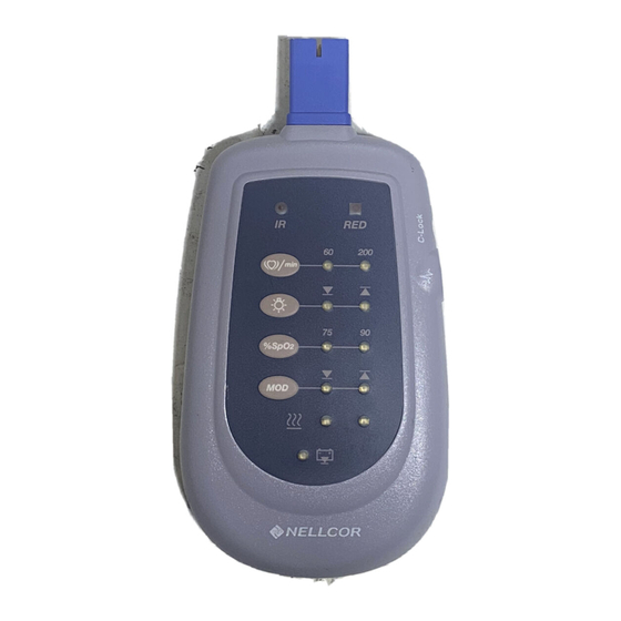
C o n t r o l s , I n d i c a t o r s , a n d S y m b o l s Note: In this manual, pulse oximeters refer to Nellcor technology-based pulse oximeters and monitors refer to OEM O technology-based monitors. -
Page 12: Controls, Indicators, And Symbols
Controls, Indicators, and Symbols Back Panel Figure 2: Back Panel Side View 1. C-LOCK connector port 2. ECG Port Figure 3: SRC-MAX Tester Side View... -
Page 13: Src-Max Buttons And Symbols
Controls, Indicators, and Symbols SRC-MAX Buttons and Symbols Front panel symbology for the SRC-MAX are as follows: Pulse rate/beats per minute (BPM) selector Button Light output selector button Percentage of Sp0 selector button Modulation selector button Feature not available at this time Battery low indicator Red LED indicator C-Lock port symbol... -
Page 14: Select Options
Controls, Indicators, and Symbols Select Options There are four button switches on the SRC-MAX Front Panel with two associated LEDs. Pulse/Beats per Minute Light Level % Sp0 Percent Modulation The pulse oximeter or monitor will display readings for both Saturation (Sp0 ) and Pulse Rate. -
Page 15: Src-Max Components And Accessories
S R C - M A X C o m p o n e n t s a n d A c c e s s o r i e s List of Components (1) SRC-MAX Functional Tester (2) AA Alkaline Batteries (1) Technical Manual Optional Accessories: Three-Lead ECG Cable... -
Page 16: C-Lock Cable
SRC-MAX Components and Accessories C-Lock Cable See Figure 6. Figure 6: C-Lock Cable... -
Page 17: Src-Max Operation With A Pulse Oximeter Or Monitor
S R C - M A X O p e r a t i o n w i t h a P u l s e O x i m e t e r o r M o n i t o r Note: In this manual, pulse oximeters refer to Nellcor technology-based pulse oximeters and monitors refer to OEM O technology-based monitors. -
Page 18: Test Setup
SRC-MAX Operation with a Pulse Oximeter or Monitor The technician must perform the test setup procedure before performing tests 1 through 4. The following is a brief description of each test: • Test Setup — This procedure establishes the baseline for all the other tests. The Test Setup procedure must be performed before performing any or all of the SRC-MAX tests. -
Page 19: Figure 7: Doc-10 Sensor Cable
SRC-MAX Operation with a Pulse Oximeter or Monitor Figure 7: DOC-10 Sensor Cable 3. Connect the SRC-MAX Sp0 sensor/cable connector to other end of the DOC-10 cable or applicable OEM cable. See Figure 8. Figure 8: SpO sensor/cable connector 4. Turn on the pulse oximeter or monitor. Refer to the applicable pulse oximeter or monitor operator’s manual. -
Page 20: Test 1: Bpm (Beats Per Minute)
SRC-MAX Operation with a Pulse Oximeter or Monitor Pulse/Beats per Minute Light Level % Sp0 Percent Modulation 8. The SRC-MAX is ready to test the pulse oximeter or monitor. Test 1: BPM (Beats per minute) The BPM test checks the pulse oximeter or monitor beats per minute operation at 60 and 200 BPM. -
Page 21: Test 2: Saturation (Sp0 2 )
SRC-MAX Operation with a Pulse Oximeter or Monitor Test 2: Saturation (Sp0 The saturation test checks the operation of the pulse oximeter or monitor percent of blood oxygen saturation at 75% and 90%. Prerequisite Procedure — Test Setup on page 12. 1. -
Page 22: Test 4: Light
SRC-MAX Operation with a Pulse Oximeter or Monitor 4. The Modulation LED indicator on the SRC-MAX will switch from the low (arrow down) value and illuminate the high value (arrow up). 5. The Plethysmographic waveform or blip bar on the pulse oximeter or monitor display will increase in amplitude within a few seconds. -
Page 23: Routine Maintenance
R o u t i n e M a i n t e n a n c e Note: In this manual, pulse oximeters refer to Nellcor technology-based pulse oximeters and monitors refer to OEM O technology-based monitors. Cleaning Caution: Do not spray, pour or spill any liquid on the SRC-MAX, its accessories, connectors, or openings in the chassis. -
Page 24: Battery Replacement
Routine Maintenance Battery Replacement Figure 9: Battery Compartment Access Press and slide the battery compartment door down to expose the batteries. See Figure 9, above. The SRC-MAX requires two AA alkaline batteries. The unit will run continuously for a minimum of 45 hours with a new set of batteries. - Page 25 Routine Maintenance The Low Battery Indicator LED will illuminate and blink when the voltage drops below 1.75 volts. There is approximately 15 minutes of use after first indication of low battery LED. It is recommended to cease operation as soon as possible and replace the batteries in the SRC-MAX.
- Page 26 (Blank Page)
-
Page 27: Performance Verification
P e r f o r m a n c e Ve r i f i c a t i o n Note: In this manual, pulse oximeters refer to Nellcor technology-based pulse oximeters and monitors refer to OEM O technology-based monitors. -
Page 28: Led Current To Photodetector Current Test
Performance Verification • Signal/Function Generator, able to deliver 0 to ±5 volts peak-to-peak at 1,000 Hz, 100 mA • Pulse oximeter or monitor • ECG monitor (RA, LA, LL) LED Current to Photodetector Current Test Note: The initial setting on the Signal Generator is 1000 Hz, Square wave, 0 to 5 volts peak-to-peak. -
Page 29: Testing The Red Led
Performance Verification Testing the RED LED 1. Turn on the signal generator. 2. Adjust the output until there is 475 to 525 millivolts peak across the 10 ohm resistor. 3. Connect one end of a 1 meg ohm resistor (R2 in Figure 11) to pin 9 of the 9 pin D-sub female connector. -
Page 30: Figure 12: Red Led Low Light Setting
Performance Verification Figure 12: RED LED Low Light Setting Note: This figure and the following waveform figures represent typical measurements. The actual measured waveforms may vary in amplitude and scale. 9. Select the High Light setting on the SRC-MAX. Measure the peak-to-peak voltage across the 1 meg ohm resistor on Channel 2 of the oscilloscope. -
Page 31: Testing The Ir Led
Performance Verification Figure 13: RED LED High Light Setting Note: The peak-to-peak voltage tolerance includes a possible probe impedance error. Testing the IR LED 1. Turn on the signal generator. 2. Adjust the signal generator output until there is -475 to - 525 millivolts peak across the 10 ohm resistor (R1 in Figure 11). -
Page 32: Figure 14: Ir Led Low Light Setting
Performance Verification Figure 14: IR LED Low Light Setting Note: The peak-to-peak voltage tolerance includes a possible probe impedance error. 5. Select the High Light Setting on the SRC-MAX. 6. Measure the peak-to-peak voltage across the 1 meg ohm resistor on Channel two of the Oscilloscope. The peak-to- peak voltage should be 2.4 to 3.6 volts peak-to-peak. -
Page 33: Bpm (Beats Per Minute) Test
Performance Verification Figure 15: IR LED High Light Setting Note: The peak-to-peak voltage tolerance includes a possible probe impedance error. BPM (Beats per Minute) Test Equipment Required • Pulse oximeter or monitor • Oscilloscope • Sub-mini 3/32” phone plug (Tip = signal, Sleeve = ground) Setup 1. -
Page 34: Figure 16: 3 Volts Peak-To-Peak At 3 Hz
Performance Verification 4. Connect the oscilloscope positive lead to the phone plug’s tip and the ground to the sleeve. 5. Adjust the oscilloscope for 3 volts peak-to-peak at 1 Hz. See Figure 16. Figure 16: 3 Volts Peak-to-Peak at 3 Hz Note: The period of the signal should be 0.96 to 1.04 seconds. -
Page 35: Bpm Test (Alternate Method)
Performance Verification Figure 17: 200 BPM 9. The period of the signal should be 0.27 to 0.33 seconds. 10. The pulse width of the signal should be 50 to 100 milliseconds. BPM Test (Alternate Method) Equipment Required: • Pulse oximeter or monitor •... - Page 36 Performance Verification 2. Select 60 BPM on the SRC-MAX. 3. Connect the 3-Lead ECG cable to the ECG monitor and the ECG port of the SRC-MAX. 4. Select Lead 1 on the ECG monitor. 5. Verify the 60 BPM reading on the ECG monitor. 6.
-
Page 37: Troubleshooting
T r o u b l e s h o o t i n g Note: In this manual, pulse oximeters refer to Nellcor technology-based pulse oximeters and monitors refer to OEM O technology-based monitors. Introduction Caution: The case of the SRC-MAC should be opened only by qualified service personnel. -
Page 38: Electromagnetic Interference
Troubleshooting Table 1: Troubleshooting Symptom Cause/Fix SRC-MAX does not power- Batteries not installed, up when attached to a pulse inserted incorrectly, or oximeter or monitor. discharged. Pulse oximeter or monitor is not powered-on. Sensor/patient cable not connected. Non-compatible pulse oximeter or monitor. Disconnect and reconnect the SRC-MAX. - Page 39 • Reorient or relocate the other receiving device • Increase the separation between the interfering equipment and this equipment • If assistance is required, contact Nellcor Puritan Bennett’s Technical Services Department or your local Nellcor Puritan Bennett representative. SRC-MAX...
- Page 40 (Blank Page)
-
Page 41: Packing For Shipment
Returned Goods Authorization (RGA) number. Unless Otherwise instructed by Nellcor Technical Services Department, it is not necessary to return any other accessory item with the tester. If the original carton is not available, use a suitable carton with appropriate packing material to protect the unit during shipping. - Page 42 (Blank Page)
-
Page 43: Specifications
S p e c i f i c a t i o n s Note: In this manual, pulse oximeters refer to Nellcor technology-based pulse oximeters and monitors refer to OEM O technology-based monitors. Controls Rate Two positions, Simulated Heart Rate:... -
Page 44: Performance
Specifications Performance Saturation (SpO 75% ±1 Sat Point 90% ±1 Sat Point Pulse Rate 60 bpm ±1 bpm 200 bpm ±2 bpm Light Levels Low Level = 750 nAi ±10% High Level = 3,000 nAi ±10% (nAi = nano-Amperes photodetector current) Modulation (%MOD) Low Modulation = 0.4% to 0.6% High Modulation = 4.5% to 5.5%... -
Page 45: Timing
Specifications Output 2: CMOS Compatible Output Timing C-Lock timing is synchronous with each optical pulse. C-Lock synchronization signals start to 45-55 msec prior to the optical pulse. C-Lock synchronization signal is 50 msec to 100 msec in width. Simulated Waveform Rise Time = 95 msec to 105 msec for all heart rates. -
Page 46: Environmental Conditions
Specifications Conditions Environmental Operation Temperature 0 ºC to 40 ºC (32 ºF to 104 ºF) Relative Humidity 15% to 95% non-condensing Altitude 2,000 m (6,561.6 feet) Transport and Storage (not in shipping container) Temperature -20 ºC to 70 ºC (-4 ºF to 158 ºF) Relative Humidity 15% to 95% non-condensing Transport and Storage (in shipping container) -
Page 47: Emc/Emi
Specifications EMC/EMI IEC 61326-1, Amendment 1 (EN 61326-1): Electrical Equipment for measurement, control and laboratory use - EMC Requirements. Radiated emissions per Federal Communication Commission (FCC) part 15. This ISM device complies with Canadian ICES-001, (CISPR 11, Class b, Group 1). CISPR 11: Industrial, Scientific and Medical (ISM) Radio- Frequency Equipment - Electromagnetic Disturbance Characteristics - Limits and Methods of Measurement. - Page 48 (Blank Page)
-
Page 49: Index
I n d e x Accessories 9 Batteries disposal 2 Battery Low indicator 5 Battery replacement 18 Beats per minute test 14, 27 Buttons 7 Cautions 1 Cleaning 17 C-Lock cable 10 C-LOCK connector port 6 C-LOCK output connector port 5 Dispose of batteries 2 DOC-10 sensor cable 13 ECG output connector port 5... - Page 50 Index Modulation test 15 Non-OXIMAX OEM monitors 2 Non-OXIMAX pulse oximeters 2 Opening the SRC-MAX 1 Operating Relative Humidity 40 Temperature 40 Operation 11 Packing 35 Percent Modulation Select Button 5 Percent Sp02 Select Button 5 Performance specifications 38 Performance verification 21 Power specifications 39 Pulse oximeter/monitor cable connector 5 Pulse rate beats per minute button 5...
- Page 51 Index Three-Lead ECG cable 9 Transport Relative Humidity 40 Temperature 40 Troubleshooting 31 SRC-MAX...
- Page 52 (Blank Page)
- Page 53 (Blank Page)
- Page 54 Tyco Healthcare Group LP Nellcor Puritan Bennett Division 4280 Hacienda Drive Pleasanton, CA 94588 USA Toll Free: 1.800.635.5267 Authorized Representative Tyco Healthcare UK LTD 154 Fareham Road Gosport PO13 0AS, U.K. © 2002 Nellcor Puritan Bennett Inc. All rights reserved. 065696A-0602...
Need help?
Do you have a question about the OxiMax SRC-MAX and is the answer not in the manual?
Questions and answers