Table of Contents
Advertisement
Quick Links
Advertisement
Table of Contents

Related Manuals for Nellcor OxiMax N-600X


Summary of Contents for Nellcor OxiMax N-600X
- Page 2 To obtain information about a warranty, if any, contact Nellcor’s Technical Services Department, or your local representative. Purchase of this instrument confers no express or implied license under any Nellcor Puritan Bennett patent to use the instrument with any sensor that is not manufactured or licensed by...
-
Page 3: Table Of Contents
C o n t e n t s Contents ............i Safety Information . - Page 4 Contents OXIMAX Sensor Attached ............ 45 No OXIMAX Sensor Attached ..........49 Turning the Backlight On or Off ............50 Adjusting the Screen Contrast ............50 Adjusting the Backlight Brightness ..........50 Selecting the Pleth View ..............51 Selecting the Blip View ..............51 Selecting the Real-Time Trend View ..........
- Page 5 Setting In-Sensor Data Type ............88 OXIMAX Sensor Data Type ............89 OXIMAX Sensor Event Record Data Available ....... 90 OXIMAX Sensor Event Record Not Available ......... 91 OXIMAX Sensor Event Record Graphical Data ......92 Viewing and Printing OXIMAX Sensor Event History Data ..... 94 OXIMAX Sensor Tabular Event Data ..........
- Page 6 Contents GCX Roll Stand ..............130 Soft-Sided Carrying Case ........... 131 Performance Considerations ........133 Overview ..................
- Page 7 Functional versus Fractional Saturation ......173 Measured versus Calculated Saturation ......174 OXIMAX Technology ..............175 Functional Testers and Patient Simulators ........176 Specifications ..........177 Performance ..................
- Page 8 Contents...
-
Page 9: Safety Information
Safety Information S a f e t y I n f o r m a t i o n Safety Warnings Warnings are identified by the WARNING symbol shown above. Warnings alert you to potential serious outcomes (death, injury, or adverse events) to the patient or user. - Page 10 Safety Information WARNING: Explosion hazard. Do not use the N-600x pulse oximeter in the presence of flammable anesthetics or gases. WARNING: Chemicals from a broken LCD display panel are toxic when ingested. Use caution when handling a pulse oximeter with a broken display panel. WARNING: Pulse oximetry readings and pulse signals can be affected by certain environmental conditions, O sensor...
-
Page 11: Safety Cautions
Safety Information Safety Cautions Cautions are identified by the CAUTION symbol shown above. Cautions alert you to exercise care necessary for the safe and effective use of the N-600x pulse oximeter. Caution: When connecting the N-600x to any instrument, verify proper operation before clinical use. - Page 12 Safety Information N-600x Operator’s Manual...
-
Page 13: Introduction
Introduction I n t r o d u c t i o n WARNING: The N-600x is intended only as an adjunct in patient assessment. It must be used in conjunction with clinical signs and symptoms. Intended Use The N-600x pulse oximeter is indicated for the continuous noninvasive monitoring of functional oxygen saturation of arterial hemoglobin (SpO ) and pulse rate. -
Page 14: How To Use This Manual
Introduction How to Use this Manual All users should read this manual thoroughly. More experienced users of the N-600x can directly go to the topics for the information they require. This manual is available on the Internet at: http://www.mallinckrodt.com/respiratory/resp/Serv_Supp/ProductManuals.html N-600x Operator’s Manual... -
Page 15: Symbols, Controls, Displays And Indicators
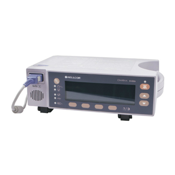
Symbols, Controls, Displays and Indicators S y m b o l s , C o n t r o l s , D i s p l a y s a n d I n d i c a t o r s About the Front Panel 12. -
Page 16: About The Rear Panel
Symbols, Controls, Displays and Indicators About the Rear Panel 1. Equipotential Terminal (Ground). 2. AC Power Connector, page 24. 3. Data Port Connector, page 112. 4. Fuse Holder. 5. Supply Voltage Selector Switch, page 24. Figure 2: Rear Panel Components N-600x Operator’s Manual... -
Page 17: About The Symbols
Symbols, Controls, Displays and Indicators About the Symbols The symbols, located on the rear panel of the N-600x, are as follows. Table 1: Symbols and Descriptions Symbol Description See Instructions for Use Fuse Replacement Equipotential Terminal (ground) Date of Manufacture Data Interface Applied Part - Not defibrillator proof Type BF... -
Page 18: About The Controls
Symbols, Controls, Displays and Indicators About the Controls ON/STANDBY Button Turns the monitor on and off. Note: Pressing a button, except the ON/STANDBY button, should result in either a valid or an invalid key tone (refer to Table 3). If the key pressed fails to emit a tone, contact qualified service personnel. -
Page 19: About The Displays
Symbols, Controls, Displays and Indicators HELP/CONTRAST Button Enables you to access the on-screen help and adjust the monitor screen contrast. • Pressing and releasing the HELP/CONTRAST button launches the on-screen help. • Pressing and holding the HELP/CONTRAST button while simultaneously pressing the ADJUST UP and ADJUST DOWN buttons lightens or darkens the display screen. -
Page 20: Blip Display
Symbols, Controls, Displays and Indicators The pleth display includes a “wiper bar” plethysmographic waveform, menu bar, and current measured %SpO and pulse rate. If SatSeconds are enabled, the pleth display includes the SatSeconds indicator and SatSeconds setting. A decimal point after the %SpO pulse rate indicates the respective limits have been changed from the power on defaults (Overview on page 73). - Page 21 Symbols, Controls, Displays and Indicators When the monitor is powered by internal battery, the blip display includes a horizontal battery fuel gauge positioned in the upper left corner that shows the remaining charge (operating hours) on battery. If a monitor reporting a low battery is connected to AC power, the battery fuel gauge shows the charging progress.
-
Page 22: Real-Time Trend Display
Symbols, Controls, Displays and Indicators Real-Time Trend Display The real-time trend display includes %SpO2 and/or pulse rate trend data plots and current measured %SpO2 and pulse rates. The trend data plots are automatically updated as each new trend point is calculated, where the interval between calculations is based on the display time scale selected. - Page 23 Symbols, Controls, Displays and Indicators The N-600x algorithm automatically extends the amount of data required for measuring SpO and pulse rate depending on the measurement conditions. During normal measurement conditions the averaging time is 6 to 7 seconds. During conditions such as those caused by low perfusion, interference (e.g., external interference like ambient light), or a combination of these, the N-600x algorithm automatically extends the amount of data required beyond 7 seconds.
-
Page 24: About The Visual Indicators
Symbols, Controls, Displays and Indicators About the Visual Indicators Table 2: Visual Indicators Indicator Description %SpO Display Shows the hemoglobin oxygen saturation level. The display value flashes zeros during loss-of-pulse alarms and flashes the SpO value when the SpO is outside the alarm limits. During Pulse Search, the monitor continues to update the display. - Page 25 Symbols, Controls, Displays and Indicators Table 2: Visual Indicators Indicator Description Low Battery Lights continuously when 15 or fewer minutes of battery capacity Indicator remain. Flashes when the battery capacity reaches a critically low condition. Battery Fuel Gauge Displays the battery charge remaining on the monitor. The battery Indicator fuel gauge consists of four bars, each corresponding to approximately 1.5 hours of operating time.
- Page 26 Symbols, Controls, Displays and Indicators Table 2: Visual Indicators Indicator Description Data In-Sensor Lights to indicate that the attached O sensor contains a patient Indicator sensor event record. The sensor event record information may be viewed or printed. SatSeconds Fills in clockwise as the SatSeconds alarm management system Indicator detects a %SpO reading outside of the limit setting.
-
Page 27: About The Audible Indicators
Symbols, Controls, Displays and Indicators About the Audible Indicators Table 3: Audible Indicators Function Description Alarm Silence Three beeps sound approximately every three Reminder minutes when alarms are silenced with the alarm silence duration set to OFF and the alarm silence reminder function is enabled. - Page 28 Symbols, Controls, Displays and Indicators Table 3: Audible Indicators Function Description Low Priority Alarm pitched, slow pulsing tone indicating an sensor disconnect, low battery, or monitor failure. Note: If a Low Priority Alarm is not silenced within 2 minutes by pressing the ALARM SILENCE Key, the monitor increases the urgency level of the audible alarm signal by alternating a piezo tone with the primary alarm...
-
Page 29: Setting Up The Monitor
WARNING: Ensure that the speaker is clear of any obstruction. Failure to do so could result in an inaudible alarm tone. WARNING: Disconnect the N-600x and Nellcor O sensor from the patient during magnetic resonance imaging (MRI) scanning. Objects containing metal can become dangerous projectiles when subjected to the strong magnetic fields created by MRI equipment. - Page 30 Do not attach any cable that is intended for computer use to the O sensor port. Do not connect any device other than a Nellcor-approved sensor to the O sensor connector. WARNING: The N-600x should not be used adjacent to or stacked with other equipment.
-
Page 31: List Of Components
Setting Up the Monitor List of Components Quantity Item -600 x Pulse Oximeter Nellcor O Sensor or Assortment Pack 10 Pulse Oximetry Cable -600 x Operator’s Manual (applicable to country of sale) and/or compact disc Power Cord (applicable to country of sale) Fuses, 0.5 A, 250 volts, slow... -
Page 32: Connecting To An Ac Power Source
(115 or 230) to avoid equipment damage and ensure battery charging. Caution: Use only the hospital-grade power cord provided by Nellcor. 1. Set the Supply Voltage Selector switch to the applicable voltage. 2. Plug the female connector end of the power cord into the power connector on the rear of the monitor. - Page 33 Setting Up the Monitor Caution: Ensure the pulse oximeter is properly grounded when operating on AC power. If you are uncertain whether the AC outlet is properly grounded, disconnect the pulse oximeter from the outlet and use the battery power. Contact a qualified electrician to examine the outlet for ground connections.
-
Page 34: Connecting An Oximax Sensor
POST with an O sensor attached. Note: Sensor LED light emissions fall within Class 1 level, according to IEC 60825-1:2001. Caution: Use only Nellcor-approved O sensors and pulse oximetry cables. Note:Physiological conditions, medical procedures, or external agents that may interfere with the monitor’s ability to detect and... -
Page 35: Operating The Battery
Operating the Battery O p e r a t i n g t h e B a t t e r y WARNING: Dispose of battery in accordance with local requirements and regulations. Operating on Battery Power The N-600x monitor has an internal battery that can be used to power the monitor during transport or when AC power is not available. - Page 36 Operating the Battery Caution: Replace the battery if fewer than four bars are lit after fully charging the battery. To charge a low or fully depleted battery, connect the monitor to AC power outlet. A full charge of a fully depleted battery takes 8 hours to charge while the monitor is turned off.
-
Page 37: Low Battery Indicator
If the monitor backlight is turned off during a low battery condition, the backlight cannot be turned back on. Nellcor recommends that a qualified service personnel replace the internal battery every 24 months. Replaced batteries should be disposed of in accordance with local ordinances. -
Page 38: Description Of Low And Critical Battery Conditions
Operating the Battery Description of Low and Critical Battery Conditions Table 4: Low and Critical Battery Conditions Critical State Operation Battery Battery Power normal AC/Battery charge LED LOW BATTERY LED LOW BATTERY message Audible alarm Error code none Effect of ALARM SILENCE key normal Shutdown... - Page 39 Operating the Battery Critical State Operation Battery Battery Power normal AC/Battery charge LED LOW BATTERY LED LOW BATTERY message Audible alarm low priority Error code logged Effect of ALARM SILENCE key First press silences audio alarm, second press cancels LOW BATTERY message (LED) stays on until Low Battery Condition is corrected.
- Page 40 Operating the Battery Critical State Operation Battery Battery Power Not used not displayed AC/Battery charge LED LOW BATTERY LED (flashing) LOW BATTERY message Audible alarm high priority Error code displayed and logged Effect of ALARM SILENCE key none Shutdown after 10 seconds N-600x Operator’s Manual...
- Page 41 Operating the Battery Critical State Operation Battery Battery Power SpO2 - displayed. AC/Battery Charge LED - LOW BATTERY LED-on (flashing) LOW BATTERY message - The Battery Fuel Gauge Indicator shows a fully depleted battery (no bars lit). Warning message in the pleth window: UNIT WILL SHUT DOWN IF AC POWER LOST...
-
Page 42: Battery Fuel Gauge Indicator
Operating the Battery Battery Fuel Gauge Indicator The N-600x has a battery fuel gauge indicator which displays the battery power remaining on the monitor. The indicator appears on the the pleth and blip display screens. When the monitor is fully charged, all four bars are lit on the battery fuel gauge indicator. -
Page 43: Using The Monitor
Using the Monitor U s i n g t h e M o n i t o r Overview This section describes menu navigation, power on/off and display options, parameter ranges, O sensor attachments, and configuring default settings suitable for your environment. Menu Description The N-600x is outlined below. -
Page 44: Menu Structure
Using the Monitor Menu Structure Main Menu LIMITS (Limits Menu) SELECT ADULT EXIT (to Main menu) TREND (Trend Menu) MON (Monitor Menu) VIEW (Monitor Trend View Menu) DUAL SPO2 PULSE NEXT (History/Amplitude Menu) HIST (Delete/Print2 Menu) DELETE (Delete Trends) “DELETE TRENDS” YES (return to Main menu) NO (back to Delete/Print menu) PRINT... - Page 45 Using the Monitor Menu Structure NEXT (Delete/Print1 Menu) DELETE (continued...) “DELETE TRENDS?” YES (to Main menu) NO (back to Delete/Print1 menu) PRINT BACK (back to Monitor menu) EXIT (to Main menu) BACK (back to Trend menu) SENSOR (Sensor/Event Menu) (if Event data is in the sensor, the following menu, the Screen will remain in the appropriate state until the next menu selection is made) GRAPH (Graph Menu) (display events #1-N, in inverse...
- Page 46 Using the Monitor Menu Structure PRINT BACK (to Trend menu) (continued...) EXIT (to Main menu) SETUP (Setup Monitor Menu) VIEW (Setup View Menu) PLETH BLIP TREND VIEW (RT Trend View Menu) DUAL SPO2 PULSE BACK ZOOM (RT Trend View Menu) TIME SCALE AUTO...
- Page 47 Using the Monitor Menu Structure BACK (back to Clock/Language menu) EXIT (to Main menu) (continued...) BACK (back to Clock/Language menu) EXIT (to Main menu) LANG (Language Setup Menu) (use up/down buttons to toggle though languages) BACK (back to Clock/Language menu) NEXT (Communication/Nurse Call Menu) COMM (Communication Port Configuration Menu) SELECT...
-
Page 48: Parameter Ranges
Using the Monitor Parameter Ranges The parameters of the N-600x monitor are preset to factory default settings. See Factory Default Settings on page 167. The factory default parameters may be changed to institutional default parameters by following the procedures in the N-600x Service Manual. Table 6 lists the parameters, ranges available, and the factory default setting. - Page 49 Using the Monitor Table 6: Parameter Ranges Factory Ranges/ Factory Parameter Neonate Selections Adult Defaults Defaults Backlight 0 to 10 Brightness Data Port 2400, 9600, 9600 9600 Baud Rate 19200 Data Port ASCII, GRAPH, ASCII ASCII Mode OXINET, CLINICAL, PHILIPS, SPACELBS, MARQ (GE Marquette),...
- Page 50 Using the Monitor Table 6: Parameter Ranges Factory Ranges/ Factory Parameter Neonate Selections Adult Defaults Defaults Pulse Rate Lower Alarm 170 bpm 190 bpm Upper Alarm Limit plus 1 to Limit 250 bpm Real-Time Saturation, Dual, Saturation Saturation Trend Pulse Rate Display Real-Time 48, 36, 24, 12, 8,...
-
Page 51: Turning On The Monitor
Caution: If any indicator or display element does not light when the pulse oximeter is turned on, do not use the pulse oximeter. Instead, contact qualified service personnel, your local Nellcor representative, or Nellcor’s Technical Services Department. Note: Physiological conditions, medical procedures, or external agents that may interfere with the monitor’s ability to detect and... - Page 52 Note:The software version shown above is only a sample. Check your monitor for the current software version installed. The software version is often needed when calling Nellcor’s Technical Services Department or your local Nellcor representative for technical assistance. Record the software version number and have it available prior to contacting technical assistance.
- Page 53 Using the Monitor WARNING: If you do not hear the POST pass tone, do not use the pulse oximeter. WARNING: Ensure the speaker is clear of any obstructions. Failure to do so could result in an inaudible alarm tone. Note:In addition to serving as the POST pass verification, the POST pass tone also functions as an audible confirmation that the speaker is performing properly.
- Page 54 Using the Monitor For a sensor containing data, the message identifies the sensor data type. For a blank sensor, the message identifies the monitor’s current data type setting used to write data to the sensor. The data type settings are SpO and SPO +BPM.
- Page 55 Using the Monitor Notice the movement of the blip bar or plethysmographic waveform or beating heart indicating the monitor is displaying real-time data. Listen for the pulse beep tone. If the pulse beep tone does not sound with each pulse, it is an indication the pulse beep volume is set to zero, the speaker is malfunctioning, or the signal is corrupt.
- Page 56 Using the Monitor When an O sensor is attached to the monitor and applied to a patient, the monitor may lose a pulse signal. If a pulse signal is lost, an alarm sounds and a poor signal condition message displays on the --- / --- monitor screen.
- Page 57 Using the Monitor No O Sensor Attached Upon successful completion of the POST process, the monitor sounds a one-second tone indicating that the monitor has passed the POST. The monitor displays dashes [ - - - ] and the Pulse Search indicator is not lit, indicating the monitor failed to detect an O sensor.
- Page 58 Using the Monitor Turning the Backlight On or Off You can turn off the backlight by pressing the LIGHT softkey and then pressing OFF. Note: Any of the following conditions turn on the backlight: • pressing any of the softkeys •...
- Page 59 Using the Monitor Selecting the Pleth View The pleth view displays the pleth waveform, %SpO , and pulse rate data. Refer to Principles of Operation on page 171, for a description of the pleth waveform. 1. With the monitor in the normal monitoring mode, press the SETUP softkey.
- Page 60 Using the Monitor 3. Press the BLIP softkey. The blip view displays. Selecting the Real-Time Trend View The real-time trend view displays the %SpO and/or pulse rate trend data. The real-time trend submenu enables you to: • select the trend data display, •...
- Page 61 Using the Monitor Selecting the Trend Data Display 1. Press the SETUP softkey. 2. Press the VIEW softkey. 3. Press the TREND softkey. 4. Press the VIEW softkey. 5. Press any of the trend softkeys (DUAL, SPO2, or PULSE). Setting the Trend Time Scale Display 1.
- Page 62 Using the Monitor Setting the Trend Amplitude Scale Display 1. Press the SETUP softkey. 2. Press the VIEW softkey. 3. Press the TREND softkey. 4. Press the ZOOM softkey. 5. Press the SCALE softkey to cycle the trend amplitude scale display through ±5 points, ±10 points, ±15 points, ±20 points, ±25 points, ±30 points, ±35 points, ±40 points and ±50 points above and below the newest - rightmost - trend data point.
- Page 63 Using the Monitor Setting the Alarm Volume The Alarm Volume display enables you to adjust the volume of alarm tones. 1. With the monitor in the normal monitoring mode, press the ALARM SILENCE button until the alarm volume level displays and sounds on the monitor.
- Page 64 Using the Monitor Setting the Date and Time WARNING: The sensor extrapolates from the date and time provided by the N-600x when recording the sensor event record to the sensor. The accuracy of the date/time is the responsibility of the N-600x. It is recommended that the N-600x user set the time/ date to the correct value before a sensor event record-enabled sensor is connected, and that this date/time not be changed while the sensor remains connected.
- Page 65 Using the Monitor 5. Press the SELECT softkey to select the TIME and DATE fields as shown in the graphic below. TIME HOURS : MINUTES : SECONDS (16 : 46 : 05) DATE DAY - MONTH - YEAR (02 - JAN - 06) 6.
- Page 66 Using the Monitor Setting the Alarm Silence Duration The Alarm Silence Duration display enables you to adjust the alarm silence duration. 1. With the monitor in the normal monitoring mode, press the ALARM SILENCE button until the alarm silence duration setting displays.
- Page 67 Using the Monitor Disabling Audible Alarms Setting the alarm silence duration to OFF disables all audible alarms. Note: The ability to set the alarm silence duration to OFF can be enabled or disabled by qualified service personnel as described in the N-600x Service Manual.
- Page 68 Using the Monitor Selecting the Standby Mode The standby mode enables the monitor to retain the alarm limit settings that are in effect while monitoring a patient. The monitor must be connected to an AC power source to enter the standby mode. Normally, the standby mode setting is used when a patient has to temporarily leave the monitor.
- Page 69 Using the Monitor Adult-Pediatric or Neonatal Settings The clinician can set the monitor’s operating mode to adult-pediatric or neonatal by using the LIMITS softkey. This setting remains active until the monitor is turned OFF. The factory default power-on setting is for adult-pediatric patients. This default setting can be changed to neonatal by qualified service personnel using the procedures indicated in the N-600x Service Manual.
- Page 70 Using the Monitor Setting Patient Adult-Pediatric or Neonatal Modes 1. With the monitor in the normal monitoring mode, press the LIMITS softkey. The monitor displays the ADULT LIMITS or NEONATE LIMITS screen, depending on the patient setting used. NEONATE LIMITS %SP02 %SPO2 UPPER...
- Page 71 Using the Monitor Alarm Limit Changed Indicator Alarm limits that have been changed from the institution or factory default settings are identified by a decimal point (.) after the displayed reading (%SpO or BPM). The changed parameter is also identified by a decimal point on the alarm limits screen.
- Page 72 Using the Monitor 1. Press the LIMITS softkey. The current alarm limits display. NEONATE LIMITS %SP02 %SPO2 UPPER LOWER SAT-S EXIT ADULT SELECT 2. Press the ADULT or NEO softkey to select the Adult-Pediatric or Neonatal alarm limits screen. 3. Press the SELECT softkey to select the parameter to be adjusted. 4.
- Page 73 Using the Monitor 6. Wait for the display to time-out to accept the changes or press the EXIT softkey to close the display and return to the normal monitoring mode. Note: Limit changes are in effect as long as the monitor remains turned on.
- Page 74 Using the Monitor Setting Monitor Response Mode The purpose of the response mode is to set the response time of the N-600x algorithm calculation of the SpO (the response mode does not affect the N-600x algorithm’s calculation of pulse rate). The trending interval (2- or 4-seconds) is updated automatically by the monitor to roughly correspond with the SpO calculation response...
- Page 75 Using the Monitor 3. Press the MODE softkey. Note: When the monitor is in the fast response mode, the monitor may produce more SpO and pulse rate alarms than you are accustomed to experiencing. 4. Use the ADJUST UP or ADJUST DOWN buttons to select the desired response mode.
- Page 76 Using the Monitor Selecting the Display Language The N-600x can be programmed to display the information in various languages. The languages available are: ENGLISH DANSK (Danish) DEUTSCH (German) ESPAÑOL (Spanish) FRANCAIS (French) ITALIANO (Italian) NEDERLANDS (Dutch) NORSK (Norwegian) PORTUG (Portuguese) SUOMI (Finnish) SVERIGE (Swedish) 1.
- Page 77 Using the Monitor 4. Use the ADJUST UP or ADJUST DOWN buttons to select the desired language. 5. Press the EXIT softkey. Note: The selected language displays until the monitor is turned OFF. The selected language can be set as a default by qualified service personnel by following the procedures outlined in the N-600x Service Manual.
- Page 78 Using the Monitor If the HELP softkey is pressed from the Condition message display, the action messages are displayed. Action messages are linked to the sensor type; action messages will be displayed for the type of O sensor connected to the monitor. Up to five action messages may be displayed.
- Page 79 Using the Monitor Sensor Adjust Messages • Message — ALTERNATE SITE? • Message — COVER SENSOR SITE? • Message — EAR/FOREHEAD SENSOR? • Message — NASAL/EAR SENSOR? • Message — O ADHESIVE SENSOR • Message — SECURE CABLE • Message — HEADBAND •...
- Page 80 Using the Monitor N-600x Operator’s Manual...
- Page 81 Using Monitor Trend Data U s i n g M o n i t o r T r e n d D a t a Overview The trend displays enable you to view trend data. Two types of trend data can be viewed: •...
- Page 82 Using Monitor Trend Data The monitor stores up to 48 hours of 4-second trend data or 24 hours of 2-second trend data. The amount of trend data displayed on the screen is determined by using the ZOOM softkey. The settings available are 20 and 40 seconds, 15 or 30 minutes, and 1, 2, 4, 8, 12, 24, 36, or 48 hours.
- Page 83 Using Monitor Trend Data Storing Trend Data Whenever the N-600x is turned on, it stores the monitor %SpO pulse rate readings in memory every 2- or 4-seconds (regardless of whether the N-600x is monitoring a patient or not). The N-600x can store up to 48 hours of 4-second trend data or 24 hours of 2-second trend data.
- Page 84 Using Monitor Trend Data Sensor Type When an O sensor is connected to the monitor, a “SENSOR TYPE:...” message is displayed for 4 to 6 seconds at the bottom of the display. The message identifies the type (model) of O sensor connected to the monitor.
- Page 85 Using Monitor Trend Data 5. Press the ZOOM softkey. The Zoom menu displays. Pressing the TIME softkey cycles the displayed trend time scale through 48 hours, 36 hours, 12 hours, 8 hours, 4 hours, 2 hours, 1 hour, 30 minutes, 15 minutes, 40 seconds and 20 seconds. Note: The 20-second and 40-second trend displays are in tabular format.
- Page 86 Using Monitor Trend Data Reading the Trend Data Display The following table identifies the components of the trend data display. Table 7: Reading Trend Display Item Description Amount of trend data displayed on the screen. Settings available are 20 and 40 seconds, 15 and 30 minutes, 1, 2, 4, 8, 12, 24, 36, and 48 hours.
- Page 87 Using Monitor Trend Data Dual Trend Data Display The dual trend data display shows both oxygen saturation (%SpO levels and pulse rate (bpm) trend data. 1. With the monitor in the normal monitoring mode, press the TREND softkey. 2. Press the MONITR softkey. 3.
- Page 88 Using Monitor Trend Data Trend Display 1. With the monitor in the normal monitoring mode, press the TREND softkey. 2. Press the MONITR softkey. 3. Press the VIEW softkey. 4. Press the SPO softkey. SpO trend data displays. Pulse Rate Trend Display 1.
- Page 89 Using Monitor Trend Data 4. Press the PULSE softkey. The pulse rate trend data displays. Histogram Trend Data Display The histogram displays trend data for the percent of oxygen blood saturation (SpO ) and pulse rate (bpm). The data displayed represents the trend data stored over the period of time indicated on the display.
- Page 90 Using Monitor Trend Data 5. Press the HIST softkey. The histogram trend data displays. Pulse Amplitude Trend Data Display The pulse amplitude trend data display shows the amplitude of the patient’s pulse rate over the period of time indicated on the display. Refer to OXIMAX Sensor Type on page 76 to setup the desired trend data scale.
- Page 91 Using Monitor Trend Data 5. Press the AMP softkey. The pulse amplitude units (PAU) trend data displays. The PAU reading (12 : 20) indicates the pulse amplitude units (upper and lower) at the cursor position (dashed line). The cursor moves right or left using the ADJUST UP (right) and ADJUST DOWN (left) buttons.
- Page 92 Using Monitor Trend Data N-600x Operator’s Manual...
- Page 93 Using OXIMAX Sensor Event Records U s i n g O S e n s o r E v e n t R e c o r d s Overview WARNING: The sensor extrapolates from the date and time provided by the N-600x when recording the sensor event record to the sensor.
- Page 94 Using OXIMAX Sensor Event Records Event records can only be viewed after an O sensor containing patient alarm data (event records) has been connected to an O monitor with SENSOR enabled. Event records are designed to view patient events from prior areas of care or transport (history) while monitor trend should be used to view data or events from a patient currently being monitored.
- Page 95 Using OXIMAX Sensor Event Records Setting up O Sensor Messages The O sensor message setup display allows you to enable or disable the O sensor message feature. When disabled, neither the “SENSOR NOT POSTING” nor the “RECOMMENDED ACTION” messages display. 1.
-
Page 96: Setting In-Sensor Data Type
Using OXIMAX Sensor Event Records Setting In-Sensor Data Type The In-Sensor Data Type display enables you to adjust the type of patient alarm event trend data to be recorded in an O sensor. sensors can be set to record either SpO or SpO +BPM. -
Page 97: Oximax Sensor Data Type
Using OXIMAX Sensor Event Records 4. Use the SELECT softkey to toggle between SENSOR-R and SENSOR-RW. 5. Use the ADJUST UP or ADJUST DOWN button to select the sensor data type. SENSOR-R and SENSOR-RW selections are: • • +BPM • DEFAULT 6. -
Page 98: Oximax Sensor Event Record Data Available
Using OXIMAX Sensor Event Records Sensor Event Record Data Available When an O sensor containing patient alarm data (single-patient-use O sensors only) is connected to the monitor, the Sensor Event Record indicator on the monitor front panel blinks at a medium priority flash rate to indicate that the O sensor attached to the monitor contains patient event data. -
Page 99: Oximax Sensor Event Record Not Available
Using OXIMAX Sensor Event Records Sensor event records can be viewed by accessing the TREND/ SENSOR menu. The SENSOR EVENT RECORD LED comes on steady when sensor memory is full and stays on until the O sensor is disconnected. Sensor Event Record Not Available If you select the TREND/SENSOR option when a connected O sensor (single-patient-use O sensors only) does not contain... -
Page 100: Oximax Sensor Event Record Graphical Data
Using OXIMAX Sensor Event Records Sensor Event Record Graphical Data Graphical representations of patient event history is only available on single-patient-use O sensors. Graphed data points are the minimum or maximum %SpO value for each 30-second interval throughout the duration of an event (%SpO continuously below alarm threshold for at least 15 seconds) and continuing every 30 seconds until the actual %SpO... - Page 101 Using OXIMAX Sensor Event Records The type of data displayed in the graph is indicated to the left of the vertical axis (%SpO ). Below this is the range of values (min./max.) during the event. The duration of the event is shown below the range value.
-
Page 102: Viewing And Printing Oximax Sensor Event History Data
Using OXIMAX Sensor Event Records Viewing and Printing O Sensor Event History Data With the monitor in the normal monitoring mode, you can connect a printer, capable of printing graphs, to the monitor data port connector in order to print O sensor event history data. - Page 103 Using OXIMAX Sensor Event Records A sequence of %SpO + BPM (saturation plus pulse rate) “dual-view” event graphs are shown below. The dual-view graph is the same as a single graphical event history graphs, except the graphs are compressed horizontally to allow both %SpO and pulse rate graphs to be shown for the same event.
-
Page 104: Oximax Sensor Tabular Event Data
Using OXIMAX Sensor Event Records Sensor Tabular Event Data The O sensor tabular event data is a listing of all events recorded on the O sensor’s memory chip. SUMMARY DATE START %SPO2 06JAN 63/70 13:55 00:03:00 75/80 06JAN 60/64 11:07 00:10:30 76/83 06JAN... -
Page 105: Viewing And Printing In-Sensor Tabular Event History Data
Using OXIMAX Sensor Event Records The ADJUST UP and ADJUST DOWN buttons on the monitor panel are used to move through the Event Summary table line by line. The PRINT softkey enables you to print the displayed event graph. The BACK softkey returns to the previous TREND/SENSOR submenu level. - Page 106 Using OXIMAX Sensor Event Records N-600x Operator’s Manual...
-
Page 107: Printing Monitor Trend Data
GRAPH MODE for printing graphical data. Printing 1. With the monitor in the normal monitoring mode, connect the serial printer to the monitor’s Data port connector, using Nellcor printer cable part number 036341. 2. Turn on the printer. - Page 108 Printing Monitor Trend Data 4. Press the COMM softkey. 5. Set the BAUD rate to the appropriate number using the ADJUST UP button. 6. Press the SELECT softkey to select PROTOCOL. 7. Set the PROTOCOL to ASCII for text printing or GRAPH for graph printing using the ADJUST UP button.
- Page 109 Printing Monitor Trend Data 12. Press the PRINT softkey. ASCII printout: GRAPH printout: N-600x Operator’s Manual...
-
Page 110: Monitor Trend Data In Ascii Mode
Printing Monitor Trend Data Monitor Trend Data in ASCII Mode Refer to Printing Monitor Trend Data on page 99 for the procedure to print trend information. The format of data displayed when a trend printout is shown in Figure 3. “TREND” is displayed in the top row. Readings are displayed in 2 or 4 second intervals depending on the response mode selected. -
Page 111: Trend Data In Graph Mode
Printing Monitor Trend Data Trend Data in Graph Mode Refer to Printing Monitor Trend Data on page 99 for the procedure to print trend information. See Figure 4. The graph mode disables all printout functions except trend data. Graph mode trend printouts are formatted for a Seiko DPU-414 and Okidata 320 serial printer. - Page 112 Printing Monitor Trend Data An example of real-time data output is shown in Figure 5. Figure 5: Real-Time Printout N-600x Operator’s Manual...
-
Page 113: Column Headings
Printing Monitor Trend Data Column Headings Every 25 line of the data output consists of a column heading. A column heading is displayed whenever the value within a column heading changes. There are three column-heading lines shown in the printout. Using the top row as the starting point there are 25 lines before the second row of column headings is printed. -
Page 114: Software Version
Printing Monitor Trend Data Software Version The next data field displays the software level (Version 4.0.0.0) and a software verification number (CRC: XXXX). Neither of these numbers should change during normal operation. Note: The numbers may change if the monitor is serviced and receives a software upgrade. -
Page 115: Response Mode
Printing Monitor Trend Data The monitor mode (ADULT or NEONATE) is identified on the printout. Response Mode The response mode (NORMAL or FAST) is identified on the printout. Data Column Headings Actual column headings are in the second row of the column heading line. -
Page 116: Time
Printing Monitor Trend Data Time The Time column displays the value of the N-600x real-time clock. Patient Data Patient information is highlighted in the display above. Parameter values are displayed directly beneath the heading for each parameter. In this example, the %SpO is 100 and the pulse rate is 190 beats per minute. - Page 117 Printing Monitor Trend Data The Status column indicates alarm conditions and operating status of the N-600x. In this example, “PH” indicates the pulse rate upper alarm limit (Pulse High) has been exceeded. A complete listing of the status codes is listed below. As many as four codes can be displayed at one time in the Status column.
- Page 118 Printing Monitor Trend Data N-600x Operator’s Manual...
-
Page 119: Using The Data Port
Using the Data Port U s i n g t h e D a t a P o r t Overview Patient data can be output through the data port on the back of the N-600x by connecting it to a PC or serial printer. When connecting the N-600x to a printer or PC, verify proper operation prior to clinical use. -
Page 120: Connecting To The Data Port
Using the Data Port Connecting to the Data Port The N-600x data port may be connected to a serial printer or PC by using a cable terminated with: • an AMP connector (AMP part number 747538-1), • ferrule (AMP part number 1-747579-2), and •... - Page 121 Using the Data Port Table 8: Data Port Pinouts Signal Name Signal Ground (isolated from Earth Ground) AN_SpO (analog saturation output) NC_NO (relay closure nurse call, normally open) NC_NC (relay closure nurse call, normally closed) (RS_422 [ ] input) Signal Ground (isolated from Earth Ground) Nurse Call (RS level output)
-
Page 122: Data Port Setup
Using the Data Port WARNING: If the serial port, analog outputs, or nurse call lines are shorted, remote communication may be lost. Data Port Setup Use the Data Port Setup display to set the baud rate and the protocol of the data port on the N-600x. The Data Port Setup display is accessed by pressing the COMM softkey on the Setup menu. - Page 123 Using the Data Port 5. Press the ADJUST UP or ADJUST DOWN buttons to select the desired protocol. The available protocols are: • ASCII • CLINICAL • GRAPH • OXINET • PHILIPS • SPACELBS (Spacelabs) • MARQ (GE Marquette) • DATEX (Datex-Ohmeda) 6.
-
Page 124: Using The Nurse Call Interface
Using the Data Port Using the Nurse Call Interface WARNING: The nurse call feature should not be used as the primary source of alarm notification. The audible and visual alarms of the pulse oximeter, used in conjunction with clinical signs and symptoms, are the primary sources for notifying medical personnel that an alarm condition exists. -
Page 125: Setting Nurse Call Rs-232 Polarity
Using the Data Port The nurse call function needs to be tested after it has been set up in your facility. The nurse call feature should be tested whenever setting up the N-600x pulse oximeter in a location that uses nurse call. If an attached O sensor is not connected to a patient, the monitor display reads zeros and the monitor remains in the Pulse Search Mode... -
Page 126: Setting Nurse Call Relays Normally Open/Closed
Using the Data Port Setting Nurse Call Relays Normally Open/Closed Data port pins 7 and 15 provide a relay that closes when an alarm is sounding on the monitor. Pins 8 and 15 provide a relay that opens when an alarm is sounding. Pin 15 is a common lead for both relays. The relay operates whether the monitor is operating on AC power or battery. - Page 127 Selecting the STEP softkey causes the voltage to increase from 0 to 1 volt at 1/10 -volt increments, with each step lasting at least 1 second. Nellcor recommends that a qualified service personnel perform the calibration of the attached device as described in the N-600x Service Manual.
- Page 128 Using the Data Port N-600x Operator’s Manual...
-
Page 129: Oximax Sensors And Accessories
OXIMAX Sensors and Accessories S e n s o r s a n d A c c e s s o r i e s WARNING: The sensor extrapolates from the date and time provided by the N-600x when recording the sensor event record to the sensor. -
Page 130: Selecting An Oximax Sensor
Do not use an O sensor with exposed optical components. WARNING: Use only Nellcor-approved O sensors and pulse oximetry cables with this pulse oximeter. Other sensors or pulse oximetry cables may cause improper N-600x performance. - Page 131 OXIMAX Sensors and Accessories WARNING: Pulse oximetry readings and pulse signal can be affected by certain ambient environmental conditions, O sensor application errors, and certain patient conditions. WARNING: Do not immerse or wet the O sensor. Caution: The O sensor disconnect error message and associated alarm indicate that the O sensor is either disconnected or the wiring is faulty.
- Page 132 For more information refer to Table 10 or contact your local Nellcor representative. Refer to OXIMAX Sensor Performance Considerations on page 135, for more information on O sensor performance.
- Page 133 OXIMAX Sensors and Accessories Table 10: Nellcor O Sensor Models and Patient Sizes Patient Model Sensor Size ® >1 kg Dura multisite oxygen sensor (Reusable, nonsterile) For use with the Dura Y sensor: Ear clip (Reusable, nonsterile) >30 kg Pedi...
-
Page 134: Oximax Sensor Features
Sensor Event Record Sensor Messages Sensor ID Message Biocompatibility Testing Biocompatibility testing has been conducted on Nellcor O sensors in compliance with ISO 10993-1, Biological Evaluation of Medical Devices, Part 1: Evaluation and Testing. The O sensors have passed the recommended biocompatibility testing and are therefore in compliance with ISO 10993-1. -
Page 135: Optional Accessories
OXIMAX Sensors and Accessories Optional Accessories Several mounting configurations, a carrying case, and a utility basket are offered with the N-600x. Contact Nellcor’s Technical Services Department or your local Nellcor representative for information about these accessories. • GCX Mounting Plate. See Figure 7 on page 128 •... -
Page 136: Gcx Mounting Plate
OXIMAX Sensors and Accessories GCX Mounting Plate An optional mounting plate is available for the N-600x. This mounting plate fits standard, commercially available GCX mount brackets, and is used to securely mount the N-600x to a wall bracket or a roll stand. The mounting plate attaches to the bottom of the N-600x as shown in Figure 7. -
Page 137: Gcx Vertical Wall Mount Arm
OXIMAX Sensors and Accessories GCX Vertical Wall Mount Arm An optional verticall wall mount arm and 19-inch channel are available and can be ordered separately for the N-600x. The vertical wall mount arm attaches to the N-600x GCX mounting plate as in in Figure 8. For further instructions regarding connecting the vertical wall mount arm, refer to the illustrated directions for use included with the vertical wall mount arm. -
Page 138: Gcx Roll Stand
GCX Roll Stand An optional GCX roll stand with utility basket with an attached handle is available from Nellcor for the N-600x. The GCX roll stand attaches to the N-600x GCX mounting plate as shown in Figure 9. For further instructions regarding connecting the GCX roll stand, refer to the illustrated directions for use included with the GCX roll stand. -
Page 139: Soft-Sided Carrying Case
OXIMAX Sensors and Accessories Soft-Sided Carrying Case An optional soft-sided carrying case is available from Nellcor for the N-600x. See Figure 10. The padded carrying case protects the N-600x while transporting the monitor. The carrying case contains two pockets for O sensors, cables, and Operator’s Manual. - Page 140 OXIMAX Sensors and Accessories N-600x Operator’s Manual...
-
Page 141: Performance Considerations
Performance Considerations P e r f o r m a n c e C o n s i d e r a t i o n s WARNING: Pulse oximetry readings and pulse signals can be affected by certain ambient environmental conditions, O sensor application errors, and certain patient conditions. -
Page 142: Performance Considerations
Performance Considerations Performance Considerations Certain patient conditions can affect the measurements of the N-600x and cause the loss of the pulse signal. Inaccurate measurements can be caused by: • incorrect sensor application • failure to cover the sensor with opaque material in high ambient light conditions •... -
Page 143: Anemia
WARNING: Tissue damage can be caused by incorrect application or inappropriate duration of use of an SpO sensor. Inspect the O sensor site as directed in the O sensor directions for use. Warning: Use only Nellcor-approved O sensors and pulse oximetry cables. N-600x Operator’s Manual... - Page 144 Performance Considerations Inaccurate measurements can be caused by: • incorrect application of the O sensor • placement of the O sensor on an extremity with a blood pressure cuff, arterial catheter, or intravascular line • ambient light • excessive patient activity •...
- Page 145 Performance Considerations WARNING: Failure to cover the O sensor site with opaque material in high ambient light conditions may result in inaccurate measurements. If patient activity presents a problem, try one or more of the following remedies to correct the problem. •...
- Page 146 Performance Considerations N-600x Operator’s Manual...
-
Page 147: Troubleshooting
Troubleshooting T r o u b l e s h o o t i n g Overview This section describes how to troubleshoot common problems while using your N-600x pulse oximeter. This chapter includes information about the on-screen help function, error code messages, and how to obtain technical help and support. -
Page 148: On-Screen Help
Troubleshooting On-Screen Help The N-600x monitor is equipped with an on-screen help system which enables you to browse and navigate through multiple help topics. Follow the steps outlined below to access and utilize the on-screen help. Accessing Multiple Topics You can access multiple on-screen help topics and select a specific topic to view. - Page 149 Troubleshooting 3. From page (2 / 2) of the HELP MAIN window, press ADJUST DOWN t to select SATSECONDS and then press SHOW. The HELP SATSECONDS window appears. The SatSeconds help topic contains a total of six consecutive help windows. 4.
- Page 150 Troubleshooting 6. Press NEXT. 7. Press NEXT. 8. Press NEXT. 9. Press BACK to view the previous windows. Continue to press BACK to return to the HELP MAIN window. 10. Press EXIT to return to the monitor’s Main menu. N-600x Operator’s Manual...
-
Page 151: Accessing Single Topics
Troubleshooting Accessing Single Topics The on-screen help enables you to access single topics by pressing the HELP/CONTRAST button from a monitor submenu. Follow the example described below to access the SatSeconds help topic. 1. Press LIMITS on the monitor Main menu and then SELECT to highlight SAT-S (SatSeconds). - Page 152 Troubleshooting 5. Press BACK. 6. Press ADJUST DOWN t to highlight NEO and then press SHOW. The HELP LIMITS NEO window appears. 7. Press BACK. 8. Press ADJUST DOWN t to highlight ADULT and the press SHOW. The HELP LIMITS ADULT window appears. 9.
-
Page 153: Error Codes
Troubleshooting Error Codes When the N-600x detects an error condition, it may display “EEE” followed by an error code. Note:The “XXX” indicates the error code number may contain up to three digits. When an error code (other than the ones listed in Table 12) is displayed, turn the instrument off and back on again. - Page 154 Troubleshooting Table 12: Error Codes Error Error Action Code Message DEFAULTS The current power on default settings LOST have been lost and returned to factory defaults. Qualified service personnel N-600x Service Manual can use the restore the desired power on default settings.
- Page 155 Troubleshooting Table 12: Error Codes Error Error Action Code Message TRENDS Monitor trends are corrupted and will LOST be cleared. Turn off the monitor, and then back on again. 701-716, POWER The monitor power supply has detected 720-724, SUPPLY an error. The monitor will shutdown 732-740, FAILURE after 10 seconds.
-
Page 156: Prompts And Error Messages
Troubleshooting Prompts and Error Messages Prompt/Error Messages are displayed in the menu area. Prompt messages alert you for a response while error messages provide information.The two figures below show examples of a prompt and an error message. Table 13 describes the N-600x prompt/error messages. Time-out is the maximum time that the message remains displayed. - Page 157 Troubleshooting Advisory messages are centered on the display. Prompts are those messages requiring a response (yes or no) and will be left justified. Table 13: Prompt/Error Messages Exit on Exit on Time Message Alarm Displayed Resolution Alarm (seconds) Silence CLOCK None After the monitor If the N...
- Page 158 Troubleshooting Table 13: Prompt/Error Messages Exit on Time Exit on Message Alarm Displayed Resolution Alarm (seconds) Silence DELETE When attempting After responding TRENDS? to delete trend to the prompt. data from memory by pressing the DELETE softkey. LOW BATTERY None When the monitor When the is on battery...
-
Page 159: Primary Speaker Failure
Troubleshooting Primary Speaker Failure The N-600x may detect a failure of the primary speaker and sound a high-pitched, slow-pulsing piezo tone. A primary speaker failure message displays as shown below. PRIMARY SPKR FAILURE: NOTIFY SVC PERSONNEL. PRESS HELP HELP 1. Press HELP to continue. The following message displays. HELP SPEAKER FAILURE Note: Once this monitor is powered... - Page 160 Troubleshooting WARNING: If an N-600x reports a primary speaker failure, do not use the monitor longer than necessary to ensure patient safety. Contact a qualified service personnel, your local Nellcor representative, or Nellcor's Technical Services Department for assistance. N-600x Operator’s Manual...
-
Page 161: Help And Support
Help and Support If you experience a problem while using the N-600x and are unable to correct it, contact qualified service personnel or your local Nellcor representative. The N-600x Service Manual, which is for use by qualified service personnel, provides additional troubleshooting information. - Page 162 One or more display elements or Do not use the N-600x pulse oximeter; contact qualified indicators do not light during the service personnel or your local Nellcor representative. power-on self-test (POST). The monitor is operating on battery •...
- Page 163 Troubleshooting Table 14: Common Problems and Resolutions Problem Resolution The Pulse Search Indicator is lit for • Check the O sensor directions for use to more than 10 seconds (before any determine if an appropriate O sensor is measurements are taken). being used and if it is applied properly.
- Page 164 Troubleshooting Table 14: Common Problems and Resolutions Problem Resolution The Pulse Search Indicator • Check the status of your patient. illuminates after successful measurements have been made. • Perfusion may be too low for the monitor to track the pulse. Test the instrument on another patient.
- Page 165 If the error code persists, record the number and provide this information to a qualified service personnel, or your local Nellcor representative. • Error Code “EEE 529 or 729" displays when the battery discharges to a critically low level.
-
Page 166: Emi (Electromagnetic Interference)
The N-600x generates, uses, and can radiate radio frequency energy and, if not installed and used in accordance with these instructions, may cause harmful interference with other devices in the vicinity. If assistance is required, contact Nellcor’s Technical Services Department, 1.800.635.5267, or your local Nellcor representative. N-600x Operator’s Manual... -
Page 167: Obtaining Technical Assistance
The N-600x Service Manual includes block diagrams and a parts list required by qualified personnel when servicing the N-600x. When calling Nellcor’s Technical Services Department, 1.800.635.5267, or your local Nellcor representative, you may be asked to tell the representative the software version number of your N-600x. - Page 168 Troubleshooting N-600x Operator’s Manual...
-
Page 169: Maintenance
The battery should be replaced at least every 24 months. Refer to the N-600x Service Manual for the battery changing procedure. If service is necessary, contact qualified service personnel or your local Nellcor representative. Periodic Safety Checks It is recommended the following checks be performed every 24 months. -
Page 170: Cleaning
Maintenance Cleaning Caution: Do not spray, pour, or spill any liquid on the N-600x, its accessories, connectors, switches, or openings in the chassis. For surface-cleaning and disinfecting the monitor, follow your institution's procedures or: • The N-600x may be surface-cleaned by using a soft cloth dampened with either a commercial, nonabrasive cleaner or a solution of 70% alcohol in water, and lightly wiping the surfaces of the monitor. -
Page 171: Using Satseconds
Such frequent alarms can be distracting. The N-600x pulse oximeter utilizes Nellcor SatSeconds alarm management technique. With the SatSeconds technique, upper and lower alarm limits are set in the same way as with traditional alarm management. - Page 172 Using SatSeconds The alarm response time, assuming a SatSeconds limit set at 50 and a lower alarm limit set at 90, is described and illustrated below. In this example, the %SpO level drops to 88 (2 points) and remains there for a period of 2 seconds (2 points x 2 seconds = 4 SatSeconds). The %SpO then drops to 86 for 3 seconds and then to 84 for 6 seconds.
-
Page 173: Satseconds "Safety Net
Using SatSeconds Saturation levels may fluctuate rather than remain steady for a period of several seconds. Often, the %SpO levels may fluctuate above and below the alarm limit, reentering the non-alarm range several times. During such fluctuations, the N-600x pulse oximeter integrates the number of %SpO points, both positive and negative, until either the SatSeconds limit (SatSeconds time setting) is reached, or the %SpO... - Page 174 Using SatSeconds N-600x Operator’s Manual...
-
Page 175: Factory Default Settings
Factory Default Settings F a c t o r y D e f a u l t S e t t i n g s Overview The N-600x is shipped with factory default settings. Authorized technical personnel using the procedures described in the N-600x Service Manual can change default settings. -
Page 176: Adult Default Settings
Factory Default Settings Table 15: Neonate Factory Defaults Parameter Setting Language English Nurse Call Polarity Normally Low Pulse Beep Volume 4 of 10 Pulse Rate Lower Alarm Limit 90 bpm Pulse Rate Upper Alarm Limit 190 bpm Real-Time Trend Display %SpO Real-Time Trend Scale 30 Minutes... - Page 177 Factory Default Settings Table 16: Adult Factory Defaults Parameter Setting Alarm Volume 7 of 10 Backlight Brightness 8 (Battery Power) 10 (AC Power) Data Port Baud Rate 9600 Data Port Protocol ASCII Display Contrast Midrange Display Format Pleth Language English Nurse Call Polarity Normally Low Pulse Beep Volume...
- Page 178 Factory Default Settings N-600x Operator’s Manual...
-
Page 179: Principles Of Operation
Principles of Operation P r i n c i p l e s o f O p e r a t i o n Overview The N-600x uses pulse oximetry to measure functional oxygen saturation in the blood. Pulse oximetry works by applying an O sensor to a pulsating arteriolar vascular bed, such as a finger or toe. -
Page 180: Automatic Calibration
Principles of Operation Because oxyhemoglobin and deoxyhemoglobin differ in light absorption, the amount of red and infrared light absorbed by blood is related to hemoglobin oxygen saturation. The monitor uses the pulsatile nature of arterial flow to identify the oxygen saturation of arterial hemoglobin. During systole, a new pulse of arterial blood enters the vascular bed, and blood volume and light absorption increase. -
Page 181: Functional Versus Fractional Saturation
Principles of Operation Functional versus Fractional Saturation This pulse oximeter measures functional saturation – oxygenated hemoglobin expressed as a percentage of the hemoglobin that can transport oxygen. It does not detect significant amounts of dysfunctional hemoglobin, such as carboxyhemoglobin or methemoglobin. -
Page 182: Measured Versus Calculated Saturation
Principles of Operation Measured versus Calculated Saturation When saturation is calculated from a blood gas partial pressure of oxygen (PO ), the calculated value may differ from the SpO measurement of a pulse oximeter. This usually occurs because the calculated saturation was not properly corrected for the effects of variables that shift the relationship between PO and pH, temperature, the partial pressure of carbon dioxide (PCO... -
Page 183: Oximax Technology
Principles of Operation Technology The N-600x pulse oximeter is designed to use Nellcor O brand sensors, which integrate the O technology. These O sensors can be identified by their deep lavender/blue plug color. All sensors contain a memory chip carrying information about... -
Page 184: Functional Testers And Patient Simulators
Many functional testers and patient simulators have been designed to interface with the pulse oximeter's expected calibration curves and may be suitable for use with Nellcor monitors and/or sensors. Not all such devices, however, are adapted for use with the Nellcor O digital calibration system. -
Page 185: Specifications
Specifications S p e c i f i c a t i o n s Performance Measurement Range 1% to 100% Pulse Rate 20 to 250 beats per minute (bpm) Perfusion Range 0.03% to 20% Accuracy Tolerance Saturation 70 to 100% ±2 digits Adult 70 to 100% ±3 digits Neonate... -
Page 186: Electrical
Specifications Accuracy Tolerance Adult specifications are shown for A and MAX sensors with the N 600x. Neonate specifications are shown for N sensors with the N 600x. Saturation accuracy varies by sensor type. Refer to the Sensor Accuracy Grid shipped with the monitor. The Sensor Accuracy Grid is available on the Internet at: http://www.mallinckrodt.com/respiratory/resp/Serv_Supp/ProductManuals.html Specification applies to N-600x monitor performance. - Page 187 Complies With 91/157/EEC Sensors Wavelength Nellcor pulse oximetry sensors contain LEDs that emit and Power red light at a wavelength of approximately 660 nm and infrared light at a wavelength of approximately 900 nm. The total optical output power of the sensor LEDs is less than 15 mW.
-
Page 188: Environmental Conditions
Specifications Environmental Conditions Operation Temperature 5 ºC to 40 ºC (41 ºF to 104 ºF) Altitude 390 m to 3,012 m 1,254 ft. to 9,882 ft.) Atmospheric Pressure 70 kPa to 106 kPa (20.6 in. Hg to 31.3 in. Hg) Relative Humidity 15% to 95% non condensing to be... - Page 189 Specifications Transport and Storage (in shipping container) Atmospheric Pressure 50 kPa to 106 kPa (14.7 in. Hg to 31.3 in. Hg) Relative Humidity 15% to 95% non condensing Sensor Power Dissipation Sensor Dissipation 52.5 mW 52.5 mW 52.5 mW 52.5 mW 52.5 mW 52.5 mW 52.5 mW...
-
Page 190: Physical Characteristics
Specifications Physical Characteristics Weight 5.8 lbs. (2.6 kg) Dimensions 3.3 in. x 10.4 in. x 6.8 in. (8.4 cm x 26.4 cm x 17.3 cm) Compliance Item Compliant With Equipment classification Safety Standards: IEC 60601 (same as EN60601 1), CSA 601.1, UL 60601-1, EN865, EN/IEC 60601 2 (second edition) -
Page 191: Manufacturer's Declaration
Specifications Item Compliant With Year of manufacture symbol EN 980 Operation during physical IEC 60068-2-27 at 100 g shock Operation during vibration IEC 60068-2-6 and IEC 60068-2-34 Electromagnetic IEC 60601-1, sub clause 36, IEC/EN Compatibility 60601-1-2 (second edition) Radiated and conducted EN 55011, Group 1, Class B emissions Operation with electrical line... - Page 192 Specifications Table 17: Electromagnetic Emissions The N-600x is suitable for use in the specified electromagnetic environment. The customer and/or user of the N-600x should assure that it is used in an electromagnetic environment as described below: Electromagnetic Emissions Test Compliance Environment Guidance RF emissions Class B...
- Page 193 Specifications Table 18: Electromagnetic Immunity The N 600x is suitable for use in the specified electromagnetic environment. The customer and/or user of the N 600x should assure that it is used in an electromagnetic environment as described below. Electromagnetic Immunity Compliance 60601 Environment...
- Page 194 Specifications Table 18: Electromagnetic Immunity The N 600x is suitable for use in the specified electromagnetic environment. The customer and/or user of the N 600x should assure that it is used in an electromagnetic environment as described below. Electromagnetic Immunity Compliance 60601 Environment...
- Page 195 Specifications Table 18: Electromagnetic Immunity The N 600x is suitable for use in the specified electromagnetic environment. The customer and/or user of the N 600x should assure that it is used in an electromagnetic environment as described below. Electromagnetic Immunity Compliance 60601 Environment...
- Page 196 Specifications Table 19: Electromagnetic Immunity, RF Portable Equipment For portable and mobile communication equipment. The N 600x is suitable for use in the specified electromagnetic environment. The customer and/or user of the N 600x should assure that it is used in an electromagnetic environment as described below: Electromagnetic Immunity...
- Page 197 Specifications Table 19: Electromagnetic Immunity, RF Portable Equipment For portable and mobile communication equipment. The N 600x is suitable for use in the specified electromagnetic environment. The customer and/or user of the N 600x should assure that it is used in an electromagnetic environment as described below: Electromagnetic Immunity...
- Page 198 Specifications Table 19: Electromagnetic Immunity, RF Portable Equipment For portable and mobile communication equipment. The N 600x is suitable for use in the specified electromagnetic environment. The customer and/or user of the N 600x should assure that it is used in an electromagnetic environment as described below: Electromagnetic Immunity...
- Page 199 Specifications Table 20: Recommended Separation Distances Recommended Separation Distances between Portable and Mobile RF Communications Equipment and the N 600x (IEC 60601 Frequency of 150 KHz to 80 MHz to 800 MHz to Transmitter 80 MHz 800 MHz 2.5 GHz Equation d = 1.2√P d = 1.2√P...
- Page 200 Specifications Table 21: Cables Cables and Maximum Complies With Length Sensors 10.0 ft. (3 m) • RF emissions, CISPR 11, 10 pulse oximetry Class B/Group 1 cable • Harmonic emissions, Software 10.0 ft. (3 m) IEC 61000-3-2 download cable, RS serial, 15 to 9 •...
- Page 201 Specifications Table 21: Cables Cables and Maximum Complies With Length Sensors • RF emissions, CISPR 11, sensors: Class B/Group 1 1.5 ft. (0.5 m) • Harmonic emissions, IEC 61000-3-2 3.0 ft. (0.9 m) 1.5 ft. (0.5 m) • Voltage fluctuations/flicker emission, IEC 61000-3-3 1.5 ft.
- Page 202 Specifications Table 21: Cables Cables and Maximum Complies With Length Sensors 3.0 ft. (0.9 m) • RF emissions, CISPR 11, Durasensor Class B/Group 1 sensor • Harmonic emissions, 100A IEC 61000-3-2 • Voltage fluctuations/flicker emission, IEC 61000-3-3 • Electrostatic discharge (ESD), IEC 61000-4-2 •...
- Page 203 Specifications Table 21: Cables Cables and Maximum Complies With Length Sensors • RF emissions, CISPR 11, 3 cable OxiCliq Class B/Group 1 sensors: 3.0 ft. (0.9 m) • Harmonic emissions, IEC 61000-3-2 • Voltage fluctuations/flicker emission, IEC 61000-3-3 • Electrostatic discharge (ESD), 4.0 ft.
- Page 204 Specifications N-600x Operator’s Manual...
-
Page 205: Index
Index I n d e x , 174 Calculated Saturation , 161 Calibration AC Power Indicator , 16 Carrying Case Adult Soft-Sided , 131 Backlight Brightness , 169 , 168 Default Settings Cautions , 61 Adult-Pediatric Patients Cleaning , 162 , 63 Alarm Limit Display Clock... - Page 206 Index , 92 Default Settings Graphical Sensor Event Record Data , 168 Adult Factory , 167 Help , 167 Neonate accessing single topics , 143 , 146, 149 Defaults Lost , 140 multiple topics , 150 Delete Trends? , 81 Histogram Trend Data Display , 68 Deutsch...
- Page 207 Index , 135 menu Sensor , 11 softkey , 133 Performance Verification Monitor , 109 Accuracy Tolerance , 177 , 109 , 134 Performance Considerations , 12 Pleth Display Returning , 159 , 16 Plethysmographic Waveform Display Monitor Displays Dashes , 49 , 68 Portuguese...
- Page 208 Index , 146 Settings Lost , 109 , 161 Safety Checks , 109 Safety Warnings , 109 SatSeconds Alarm Management , 163 softkey , 163 Describing , 11 menu bar Display , 165 , 131 Soft-Sided Carrying Case Safety Net , 165 , 44 Software Version...
- Page 209 Index , 19 , 81 Invalid Button Press Histogram , 20 , 82 Low Priority Alarm Pulse Amplitude Medium Priority Alarm , 19 Pulse Rate , 80 , 20 , 78 Piezo Tone Reading the Power-On Self-Test Pass , 20 Scale , 76 , 20...
- Page 210 Index N-600x Operator’s Manual...
- Page 212 Nellcor Puritan Bennett Division 4280 Hacienda Drive Pleasanton, CA 94588 U.S.A. Telephone Toll Free 1.800.635.5267 Authorized Representative Tyco Healthcare UK LTD 154 Fareham Road Gosport PO13 0AS, U.K. Rx ONLY © 2007 Nellcor Puritan Bennett LLC All rights reserved. 10006662B-0507...
Need help?
Do you have a question about the OxiMax N-600X and is the answer not in the manual?
Questions and answers