Table of Contents
Advertisement
Quick Links
OPERATOR'S MANUAL
NELLCOR
®
N-200
Pulse Oximeter
To contact Nellcor's representative: In the United States, call 1-800-NELLCOR or
510 463-4000; outside of the United States, call Nellcor's local representative.
Caution: Federal law (U.S.) restricts this device to sale by or on the order of a
physician.
© 2003 Nellcor Incorporated. All rights reserved.
066515-0203
Advertisement
Table of Contents
Troubleshooting

Related Manuals for Nellcor N-200


Summary of Contents for Nellcor N-200
- Page 1 N-200 Pulse Oximeter To contact Nellcor’s representative: In the United States, call 1-800-NELLCOR or 510 463-4000; outside of the United States, call Nellcor’s local representative. Caution: Federal law (U.S.) restricts this device to sale by or on the order of a physician.
- Page 2 To obtain information about a warranty, if any, for this product, contact Nellcor Technical Services or your local Nellcor representative. NELLCOR, DURASENSOR, DURA-Y, OXIBAND, OXICLIQ, OXISENSOR, OXISENSOR II, OXINET, C-LOCK, and the Nellcor knob configuration are trademarks of Nellcor Incorporated. ThinkJet is a trademark of Hewlett-Packard Company.
-
Page 3: Table Of Contents
CONTENTS Figures Tables Safety Information ..............Warnings................General ................ Alarms................Electrical ..............Sensors ............... Measurements ............. Symbols ................... Quick Guide to Operation ............Basic Operation ..............Alarm Functions ..............Check Alarm Limits............Adjust Alarm Limits ............Adjust Alarm Volume ........... Silence Alarm Temporarily........... - Page 4 Rear-Panel Switches ........... 20 C-13-200 and C-20-200 Patient Modules ....20 C-13-200M Patient Module ......... NELLCOR Sensors ..............23 Selecting a NELLCOR Sensor ........... 23 Cleaning and Reuse ............24 Performance Considerations ..........25 Guide to Operation ..............27 Basic Operation ..............27 Pulse Oximetry Subsystem Features.........
- Page 5 Electrical Characteristics............ 88 Physical Characteristics............. 89 FIGURES Oxyhemoglobin Dissociation Curve ........13 N-200 Front Panel ............. 16 Interface/Powerbase Rear Panel ........18 C-13-200 and C-20-200 Patient Modules ......20 C-13-200M Patient Module ..........21 Standard Limb Lead Selection ........... 36 Sample ThinkJet Trend Graph ...........
-
Page 7: Safety Information
General DANGER! Explosion hazard. Do not use in the presence of flammable anesthetics. The N-200 is to be operated by qualified personnel only. Before use, carefully read this manual, accessory directions for use, all precautionary information, and specifications. The user must check that the equipment functions safely and see that it is in proper working condition before being used. -
Page 8: Alarms
Safety Information Alarms Do not silence the audible alarm or decrease its volume if patient safety could be compromised. Check the audible alarm silence duration before temporarily silencing the audible alarm. Each time the monitor is used, check alarm limits to ensure they are appropriate for the patient being monitored. -
Page 9: Measurements
Safety Information Measurements Loss of pulse signal can occur for the following reasons: ¥ The sensor is too tight. ¥ There is excessive illumination, such as from sunlight or a surgical or bilirubin lamp. ¥ The sensor is placed on an extremity with a blood pressure cuff, arterial catheter, or intravascular line. -
Page 11: Symbols
SYMBOLS Attention: Refer to Manual Fuse Replacement Symbol Caution: Shock Hazard... -
Page 13: Quick Guide To Operation
Connect the sensor to the patient module. Plug the N-200 into a properly grounded AC outlet using a hospital-grade power cord. Alternatively, operate the N-200 on its internal battery. Turn on the system: switch the ON/STDBY switch to the ON position. -
Page 14: Adjust Alarm Volume
Quick Guide to Operation Adjust Alarm Volume Simultaneously, press the LOW SAT and HIGH SAT buttons. Turn the control knob until the desired setting appears in OXYGEN SATURATION display. Pushing the LOW SAT and HIGH SAT buttons activates the audible alarm to indicate volume. -
Page 15: Features
The NELLCOR N-200 pulse oximeter measures functional oxygen saturation of arterial hemoglobin (SpO ), and pulse rate. The system consists of three components: the N-200 pulse oximeter, an interface/powerbase, and a patient module. The N-200 monitors SpO and pulse rate continuously and noninvasively, with measurements updated at each pulse beat. -
Page 16: Oximeter Configurable Settings
Features Oximeter Configurable Settings The N-200 provides the operator with the capability to tailor the system for specific clinical applications. Capabilities include: • Audible alarms that can be silenced; the alarm has adjustable volume. • C-LOCK ECG synchronization that enhances oximetry signal processing during patient movement or for patients with low perfusion. -
Page 17: Principles Of Operation
PRINCIPLES OF OPERATION Operating Principles OPERATING PRINCIPLES Pulse oximetry is based on two principles: that oxyhemoglobin and deoxyhemoglobin differ in their absorption of red and infrared light (that is, spectrophotometry), and that the volume of arterial blood in tissue (and hence, light absorption by that blood) changes during the pulse (that is, plethysmography). -
Page 18: Automatic Calibration
Principles of Operation The delay between the electrical ECG pulse and the optical pulse at the sensor site is relatively stable for a given patient and sensor site. C-LOCKprocessing takes advantage of this temporal relationship, using the QRS complex as a reference point for identifying the oximetry pulse and for timing SpO measurements. -
Page 19: Measured Versus Calculated Saturation
Principles of Operation Measured versus Calculated Saturation When saturation is calculated from a blood gas partial pressure of oxygen (PO ), the calculated value may differ from the SpO measurement of a pulse oximeter. This usually occurs because the calculated saturation was not appropriately corrected for the effects of variables that shift the relationship between PO and saturation (Figure 1): pH, temperature, the partial pressure of carbon dioxide (PCO... -
Page 21: Setup
SETUP Unpacking and Inspection Testing Components UNPACKING AND INSPECTION Notify the carrier immediately if the N-200 shipping carton is damaged. Carefully unpack the instrument and its accessories. Confirm that the following items are included: N-200 pulse oximeter interface/powerbase hospital-grade power cord patient module operator’s manual... -
Page 22: Components
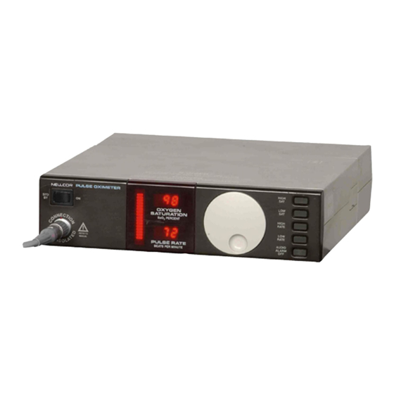
Front Panel 2 3 4 HIGH BATT BATT PULSE HIGH SEARCH SpO 2 PERCENT RATE RATE REFER LOST MANUAL AUDIO ALARM BEATS PER MINUTE 14 13 Figure 2: N-200 Front Panel... - Page 23 11. PULSE RATE display. 12. Pulse amplitude indicator: Vertical column of light bars that qualitatively indicates pulse amplitude. 13. ECG IN USE indicator: Flashes when the N-200 locates an ECG signal; lights steadily when the N-200 locks onto the signal.
-
Page 24: Interface/Powerbase Rear Panel
FORMAT 1 2 3 4 5 6 7 8 BAUD RATE REFER TO MANUAL MADE IN USA NELLCOR INC, PLEASANTON, CA 94588 32 31 27 26 1 2 3 4 5 6 7 8 Figure 3: Interface/Powerbase Rear Panel 16. ZERO button: Provides a zero-volt signal on PULSE, SAT, and RATE analog outputs. - Page 25 Setup 23. Baud Rate switches: Set the baud rate for serial communications. 24. RS-232 Format switches: Set the RS-232 format. 25. Adult/Neonatal Alarm switch: Sets the default alarm limits for adults or neonates. 26. RATE connector: Provides analog voltage output of pulse rate in beats per minute, with a range of 0–250 bpm.
-
Page 26: Rear-Panel Switches
RS-232 format Not used 7, 8 Baud rate select C-13-200 and C-20-200 Patient Modules Caution: Use only an N-200 patient module. Using an N-100 patient module may adversely affect oximeter performance. Figure 4: C-13-200 and C-20-200 Patient Modules 34. Self-adhering strap 35. -
Page 27: C-13-200M Patient Module
Setup C-13-200M Patient Module Figure 5: C-13-200M Patient Module 37. Sensor lock and connector: For NELLCOR sensors; includes lock to hold sensor in place. -
Page 29: Nellcor Sensors
NELLCOR SENSORS Selecting a NELLCOR Sensor Cleaning and Reuse Performance Considerations WARNING: Use only NELLCORoxygen transducers (sensors). Other oxygen transducers may cause improper oximeter performance. WARNING: Before use, carefully read the sensor directions for use. SELECTING A NELLCOR SENSOR When selecting a sensor, consider the patient’s weight and... -
Page 30: Cleaning And Reuse
NELLCOR Sensors Table 2: Selected NELLCOR Sensors Patient Oxygen Transducer Model Weight ¨ ¨ II or OXISENSOR N-25 <3 kg, >40 kg OXISENSOR (sterile, single use) I-20 3 to 20 kg D-20 10 to 50 kg D-25(L) >30 kg R-15 >50 kg... -
Page 31: Performance Considerations
NELLCOR Sensors PERFORMANCE CONSIDERATIONS Always select an appropriate sensor, apply it as directed, and observe all warnings and cautions. If ambient light affects performance, ensure that the sensor is properly applied, and cover the sensor site with opaque material. Failure to do so may result in inaccurate measurements. -
Page 33: Guide To Operation
(see “Determining Software Version” in the Maintenance section). Plug in the power cord to the N-200 power inlet and to an outlet supplying the appropriate mains voltage. Use only an outlet that has a grounding connection and the original hospital-grade plug and cord or an equivalent hospital- grade plug and cord. -
Page 34: Pulse Oximetry Subsystem Features
ECG, the pulse tone changes from a beep to a warble. Check the alarm limits each time the N-200 is used by sequentially pressing the HIGH SAT, LOW SAT, HIGH RATE, and LOW RATE buttons. -
Page 35: Alarm Functions
Changing Pulse Tone Volume Turn the control knob to adjust pulse tone volume. When the N-200 is turned off and back on again, the pulse tone returns to its default volume. Alarm Functions WARNING: When the AUDIO ALARM OFF button has... - Page 36 The visible alarm cannot be turned off. Checking Alarm Limits Check the alarm limits each time the N-200 is used, by sequentially pressing the HIGH SAT, LOW SAT, HIGH RATE, and LOW RATE buttons. The unit displays each limit in turn.
-
Page 37: Default Alarm Settings
Guide to Operation Default Alarm Limits Default alarm limits are in effect when the N-200 is turned on. There are two sets of default alarm limits, one for adults and one for neonates as shown in Table 3. Table 3: Default Alarm Settings... - Page 38 Guide to Operation Adjusting Audio Alarm Volume WARNING: Do not set the alarm volume too low to be heard. WARNING: When the AUDIO ALARM OFF button has been pressed and the AUDIO ALARM OFF indicator is illuminated, no audio alarm sounds in the event of an adverse patient condition.
-
Page 39: Oximetry Operating Modes
60seconds. Oximetry Operating Modes The three operating modes of the N-200 enable it to make accurate measurements despite differing levels of patient activity. In all three modes, the N-200 updates its measurements with every pulse beat. -
Page 40: C-Lock Ecg Synchronization
ECG leads directly to the connector on the NELLCOR C-13-200 or C-20-200 patient module. To provide reliable saturation measurements in a high-motion environment or when a patient has poor perfusion, the N-200 can use an ECG (R-wave) signal to identify the pulse and synchronize the saturation measurements. - Page 41 When the ECG signal is lost, oximetry measurements will continue to be derived from the optical sensor signal. During this time the N-200 continues to search for an ECG signal, and, when it finds an adequate signal, C-LOCK ECG synchronization again becomes active. To cancel the ECG LOST indication, press the AUDIO ALARM OFF button.
-
Page 42: Standard Limb Lead Selection
(high-level output) from the external ECG monitor to the interface/powerbase ECG IN/OUT connector. Use only a Nellcor-supplied or Nellcor-approved ECG patch cord and connect the patch cord as described in its Directions for Use. It is important to select the appropriate patch cord for each ECG monitor. - Page 43 Directions for Use. Connect the sensor to the NELLCOR patient module, and verify that a saturation value is displayed by the N-200 and that the ECG IN USE indicator lights steadily. Test all instrument functions under both normal and alarm conditions (for example, ECG leads off) to ensure appropriate operation before clinical use (see the operator’s...
-
Page 44: Trend And Event Memories
Day and minute settings appear in the PULSE RATE display. The N-200 sets the year, month, day, hour, and minute sequentially. If more than 5 seconds elapse between any of the steps listed above, the changes made so far are stored and the N-200 starts the sequence again (beginning with year). - Page 45 N-200 rear-panel SERIAL COMM connector according to the instructions in the Connecting to Other Instruments section. To print trend data in graphic form, set the N-200 RS-232 format switches to graphics mode I or II as described in the same section.
- Page 46 Guide to Operation The following automatic markers appear on ThinkJet trend graphs: Occurrence Marker Alarm-limit event User-defined event Power turned off Pulse signal is lost Clock is reset Signal is acquired Whenever an A marker appears, the trend graph ends and a new one begins.
-
Page 47: Sample Thinkjet Trend Graph
3/25 (L2:53) and the signal lost at 5:58 a.m. on 3/25 (S5:58) Using an Analog Strip-Chart Recorder: Connect the strip- chart recorder to the N-200, as described in the Connecting to Other Instruments section. Calibrate the recorder, adjust the settings as necessary, and confirm proper operation. If the N-200 is also connected to a graphics printer, that printer must be turned off. - Page 48 Time when signal is acquired A full-scale to current-value deflection Time when pulse signal is A full-scale to current-value lost deflection Time when N-200 is turned A full-scale to current-value deflection Event-limit or user-defined A full-scale to zero-voltage event deflection Note: The monitor can only store 60 events;...
-
Page 49: User-Defined Events
Guide to Operation Events The event memory stores a snapshot of concurrent oxygen saturation, pulse rate, and pulse amplitude measurements. During the snapshot, measurements are obtained once every second, resulting in a data display that has higher resolution than the trend memory. Up to 1 hour of event data may be stored. -
Page 50: Limit Events
To set event limits that differ from the alarm limits, the N-200 must be operating on AC power. Press and hold the applicable alarm button (HIGH SAT, LOW SAT, HIGH RATE, or LOW RATE) and the rear-panel EVENT button;... - Page 51 I or II as described in the same section. To print events in graphic form, press the EVENT button on the back of the N-200. The events are printed when the button is released. When event data is output on a ThinkJet printer, the earliest data is in the top left of the page.
-
Page 52: Sample Thinkjet Event Graph
Guide to Operation Figure 8 illustrates event output on a ThinkJet printer. Figure 8: Sample ThinkJet Event Graph Note: A user-defined event started at 4:37 p.m. on 3/22 (E16:37) and an alarm-limit event started at 2:20p.m. on 3/24 (L14:20). To Determine the Number of Events in Memory: press and hold the LOW SAT and LOW RATE buttons. - Page 53 Using an Analog Strip-Chart Recorder: Connect the strip- chart recorder to the N-200, as described in the Connecting to Other Instruments section. Calibrate the recorder, adjust the settings as necessary, and confirm proper operation. If the N-200 is also connected to a graphics printer, that printer must be turned off.
- Page 54 Do not attempt to print event data on a NELLCOR N-9000 recorder/interface. Sending Trend and Event Data to ASCII Devices: Trend and event data collected by the N-200 is available to ASCII devices through the SERIAL COMM connector. See Connecting to Other Instruments section for more information on trend and event data and RS-232 formats.
-
Page 55: Communications Formats
E On appears. When the memories are disabled, the operator can still trigger a user-defined event, as previously described. When the N-200 is turned off and back on again, the memories are made active again. Communications Formats... - Page 56 HH:MM:SS: MONITOR: RATE = nnn %O2 SAT= nnn PULSE AMPL. %FS = nnn HH:MM:SS: MONITOR: NO PULSE DATA HH:MM:SS is the time set on the N-200’s internal clock and %FS is the pulse amplitude expressed as a percentage of full scale.
- Page 57 LOW RATE = nnn HIGH RATE = nnn LOW SAT = nnn HIGH SAT = nnn If the N-200 is turned off or the interface/powerbase is detached from the monitor, the following sequence is transmitted immediately and again once each minute:...
- Page 58 Guide to Operation Switch section 2 up (Alternate Computer Format and to some Spacelabs monitors). Once every 10 seconds, and when the status or limits change, the following data is transmitted: <STX>RnnnSnnnPnnnLnnnHnnnOnnnAnnnMnnnTnnnnnn Qnnn<CR><LF><ETX><CHKSM><ETX> Note: STX (start of transmission) and ETX (end of transmission) are shown in hexadecimal equivalents above their positions in the string.
- Page 59 Trend and Event Command Format: The following information describes the data that will be sent to and received from the N-200. The monitor responds to these commands in any of the six ASCII modes. Common parameters in these expressions are: Text Marker Hexadecimal Meaning of Marker <...
- Page 60 SEND TREND Device Sends: W< CRLF > N-200 Responds: < STX > W < CRLF > < ETX > — Sent once when command received. Z, W, [Y] * A Z packet, followed by a number of W and Y packets. The number of W packets is given by the first parameter Zn .
- Page 61 Command: STOP SENDING Device Sends: V < CRLF > N-200 Responds: < STX > V128< CRLF > < ETX > — Sent once when command received. Note: The Y data packets may occur at any time during the trend or event dump. The positions of the Y packets indicate when the associated event occurred.
- Page 62 This is the last record sent to indicate end of data in normal completion. V Packet < STX > Vnnn < CRLF > < ETX > This is sent only if the N-200 stops before the requested data transmission is complete. It indicates why the N-200 stopped. Reason for Stop Timeout error...
- Page 63 Guide to Operation Xn . . . n Event data point (n . . . n = current index up to four digits) Snnn Saturation Rnnn Pulse rate Pnnn Pulse amplitude Y Packet < STX > YnDnnnnnnnn < CRLF > < ETX > This is the time marker description indicating the type of marker and the time it occurred.
-
Page 64: Interface/Powerbase
ASCII device is connected. If the DSR signal input (pin 6 on the SERIAL COMM connector) is not true, no output occurs. Hence any ASCII device connected to the N-200 must drive the DSR pin 6 to a logic true to output trend and event data to the serial communications port. -
Page 65: Battery Operation
Battery Operation If AC power is lost or the interface/powerbase is disconnected, the N-200 operates on its internal battery (typically 90 minutes for a new, fully charged battery). When the battery level is too low to power the instrument reliably, an internal switch turns off the N-200 automatically. -
Page 67: Connecting To Other Instruments
IEC 601.1.1. If in doubt, contact NellcorÕ s Technical Services Department or your local Nellcor representative. This section contains information to allow the user to provide serial communications between the N-200 and external digital devices. RS-232 COMMUNICATION PROTOCOL Serial Data Connector Pin Assignments... -
Page 68: Serial Comm Connector Pin Assignments
Connecting to Other Instruments Table 4: SERIAL COMM Connector Pin Assignments Output Output Connector Signal Device Device Direction Signal not used none none none Rx data Tx data ← Tx data Rx data → → Signal Ground Signal Ground ↔ ←... -
Page 69: Communications Formats
The RS-232 format switches are used to set the communication port format, as shown in Table 5. The serial communication format of the N-200 is eight data bits, no parity bit, and one stop bit. Table 5: Output Format Switch Settings... - Page 70 Table 5: Output Format Switch Settings (continued) Format Switch Sections Name Description N-9000 Used with Down Down Down Recorder and NELLCOR N-7000 N-9000 and Interface N-7000 recorder/ interface units Graphics Suppresses sign- Down Mode I on message and real-time data output;...
-
Page 71: Setting Baud Rate
The NELLCOR N-7000 is not available outside the United States. The N-7000 provides RS-232 or RS-485 interface capabilities to the N-200. Data from the N-200 is transmitted through a fiber- optic cable to the N-7000. The N-7000 outputs data via a standard 25-pin Dconnector. -
Page 72: Connecting To The N-7500 Network
3, 4, 5, and 7 down; switch 8 up. CONNECTING THE N-9000 RECORDER/INTERFACE Connect the N-9000 to the N-200 as follows: Set the N-200 baud rate switches to 2400 (switch 7 down; 8 up). Set the N-200 RS-232 FORMAT switches to the N-7000/ N-9000 recorder format (switch sections 3–5 down). -
Page 73: Connecting Other Strip-Chart Recorders
The N-200 analog output connectors are standard 3/32-in. subminiature phone plugs. The output voltage range required by the recorder (0–1 V or 0–10 V) is set with the N-200 VOLTAGE switch. The oxygen saturation output can be set for a 0–100% display or an expanded 50–100% display using the N-200 SpO % SCALE switch. -
Page 74: Connecting The Thinkjet Printer
Connect the ThinkJet printer to the N-200 as follows: Set the N-200’s baud rate to 19.2 K using the baud rate switches: 7 and 8 up. Set the N-200 format using the RS-232 format switches: 3–4 up, 5 down (Graphics Mode I);... -
Page 75: Connecting The P-200 Printer
On the row of six switches, set 4, 5, and 6 down; all others are up Connect the printer to the N-200 using the interface cable provided with the P-200 printer. Turn on the printer and verify proper operation (see the... -
Page 77: Maintenance
NELLCOR N-200 service manual. CLEANING Caution: Do not immerse the N-200 in liquid or use caustic or abrasive cleaners. To clean the N-200’s surfaces, dampen a cloth with a commercial, nonabrasive cleaner and wipe the top, bottom, and front surfaces lightly. -
Page 78: Determining Software Version
Nellcor’s Technical Services Department or your local Nellcor representative. DETERMINING SOFTWARE VERSION To determine the N-200 software version, press the HIGH SAT and AUDIO ALARM OFF buttons. A two-digit version number appears in the PULSE RATE display. For example, version 2.7 appears as 27. -
Page 79: Returning The N-200
Maintenance RETURNING THE N-200 If it is necessary to return the monitor to Nellcor, call Nellcor’s Technical Services Department for shipping instructions. To repack the N-200, disconnect the patient module, and wrap each separately. If necessary, the powerbase may be disconnected from the monitor. -
Page 81: Troubleshooting
ALL clr Trend and event memory has been erased. The N-200 erases and reinitializes the memories if data has been corrupted or were erased. The memories can also be manually cleared and reinitialized. In both cases, the ALL clr appears. - Page 82 Err Pb The powerbase is not communicating with the N-200. Disconnect the powerbase from AC power, turn the N-200 off and back on again, and reconnect the powerbase to AC power. If this does not solve the problem, contact qualified service personnel.
-
Page 83: Troubleshooting Guide
Battery-backed memory contents have been lost, and the trend memory was erased and reinitialized. The trend memory operates normally as long as the N-200 is turned on, but when the ON/STDBY switch is set to STDBY, the trend memory will be erased. -
Page 84: General System Problems
14hours to recharge the N-200 battery completely. • Check AC fuse. 2. N-200 operates on AC power but not on battery. • The battery may be discharged. To recharge the battery, connect the N-200 to the interface/powerbase. Plug the power cord into an appropriate AC power outlet and confirm that the BATT IN USE indicator is off. -
Page 85: General Oximetry Subsystem Problems
Move the sensor to an alternate site that is not affected. • The patient’s perfusion may be too low for the N-200 to detect an acceptable pulse. • Use C-LOCK ECG synchronization; test the N-200 on someone else;... - Page 86 Troubleshooting • Excessive patient motion may be making it impossible for the N-200 to find a pulse pattern. If possible, keep the patient still; check whether the sensor is applied securely and properly and replace if necessary; use C-LOCK ECG synchronization; move the sensor to a new site;...
- Page 87 Troubleshooting – Move the electrosurgical unit ground pad as close to the surgical site as possible. • The sensor may be damp or may have been reused too often. Replace it. • If using a sensor extension cable, remove it and connect the sensor directly to the patient module.
- Page 88 • Excessive patient motion may be making it impossible for the N-200 to find a pulse pattern. If possible, keep the patient still; check whether the sensor is applied securely and properly and replace if necessary; use C-LOCK ECG synchronization; move the sensor to a new site;...
- Page 89 • Fractional measurements may not have been converted to functional measurements before the comparison was made. The N-200, as well as other two-wavelength oximeters, measure functional saturation. Multi- wavelength oximeters, such as the Instrumentation Laboratory282 CO -Oximeter and Corning CO-oximeters, measure fractional saturation.
-
Page 90: Trend Memory Problems
IN/OUT connector on the rear panel of the N-200. Trend Memory Problems 14. Trend data is not available. • The N-200 may not be plugged into a functional outlet supplying mains power. • Data in the trend memory may have been erased. -
Page 91: Specifications
SPECIFICATIONS Performance Environmental Conditions Electrical Characteristics Physical Characteristics PERFORMANCE Range Saturation 0–100% Pulse Rate 20–250 bpm (beats per minute) - Page 92 Rubbing: 1-2 cm amplitude at an aperiodic* frequency between 1-4 Hz (*Note: “aperiodic” is a randomly changing frequency) Adult specification is shown for D-25 and N-25 sensors with the N-200. Neonate specification of D-25 and N-25 sensors was shown for N-25 sensors with the N-200. Validation testing conducted on adult volunteers.
- Page 93 Specifications Direct ECG input Via C-13-200 or C-20-200 patient module Input Defibrillator protected, differential; Lead II only Bandwidth 0.5–40 Hz (monitoring bandwidth) CMRR Greater than 100 dB at 50 or 60 Hz with 5 kilohms source imbalance Input Range ±0.5-5.0 mV for QRS detection Input Impedance greater than 10 megohms Via Rear-Panel ECG IN/OUT Connector...
-
Page 94: Environmental Conditions
ECG wave out or ECG wave/defib sync input Voltage 0–1 V or 0–10 V (switch-selectable) Range Set 0–100% or SpO 50–100% (switch-selectable) Accuracy ±20 mV at zero, ±0.5% of full scale, referred to front-panel display ENVIRONMENTAL CONDITIONS Temperature N-200 41–107.6°F (5–42°C) operating 32–122°F (0–50°C) storage... -
Page 95: Electrical Characteristics
Specifications Sensor Within physiologic range 82.4–107.6°F (28–42°C) for accurate measurement. Humidity Any humidity/temperature combination without condensation. Altitude 0–10,000 ft (0–3,048 m) ELECTRICAL CHARACTERISTICS Protective Class Class I: mains-supplied unit using a protective ground Degree of Protection Type BF: patient electrically isolated Voltage 100 VAC -10% to 120 VAC +10%, 50/60 Hz Power Consumption... -
Page 96: Physical Characteristics
N-200 only 5 lb (2.3 kg) With powerbase 8 lb (3.7 kg) Patient Module Cable length 13 ft (4 m) cable (C-13-200, C-13-200M) 20 ft (6 m) cable (C-20-200) Connector Lemo B-series, mates with 12-pin connector on N-200 front panel...
Need help?
Do you have a question about the N-200 and is the answer not in the manual?
Questions and answers