Sony DCR-TRV6 Service Manual
Digital video camera recorder
Hide thumbs
Also See for DCR-TRV6:
- Operating instructions manual (163 pages) ,
- Limited warranty (1 page) ,
- Operating instructions manual (152 pages)
Table of Contents
Advertisement
SERVICE MANUAL
SERVICE MANUAL
Level 2
On the VC-240/241 board
This service manual provides the information that is premised the
circuit board replacement service and not intended repair inside the
VC-240/241 board.
Therefore, schematic diagram, printed wiring board and electrical parts
list of the VC-240/241 board are not shown.
The following pages are not shown.
Schematic diagram .......................... Pages 4-17 to 4-66
Printed wiring board ......................... Pages 4-67 to 4-74
Electrical parts list ............................ Pages 6-23 to 6-44
DCR-TRV6/TRV6E/TRV11/
TRV11E/TRV20/TRV20E
Ver 1.1 2000. 06
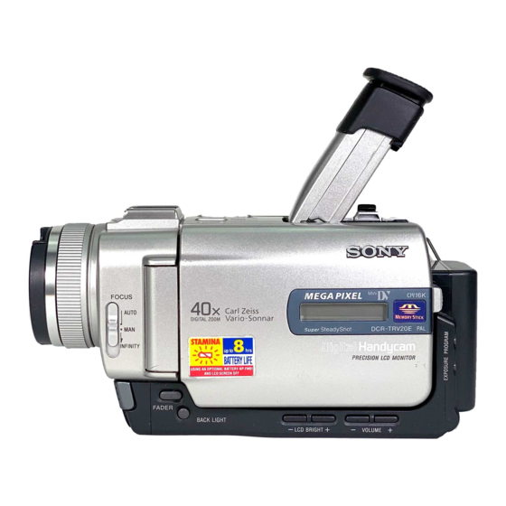
Photo : DCR-TRV20E
RMT-811
For MECHANISM ADJUSTMENTS, refer to the
"DV MECHANICAL ADJUSTMENT MANUAL
J MECHANISM " (9-929-807-11).
DCR-TRV6/TRV11/TRV20
DCR-TRV6E/TRV11E/TRV20E : PAL model
• Table showing differences is shown on page 4.
SPECIFICATIONS
DIGITAL VIDEO CAMERA RECORDER
RMT-808/809/811/812
US Model
Canadian Model
Korea Model
DCR-TRV6/TRV11/TRV20
AEP Model
UK Model
Australian Model
Chinese Model
DCR-TRV6E/TRV11E/TRV20E
E Model
Hong Kong Model
Tourist Model
DCR-TRV6/TRV6E/TRV11/
TRV11E/TRV20/TRV20E
J MECHANISM
: NTSC model
— Continued on next page —
Advertisement
Table of Contents

Related Manuals for Sony DCR-TRV6


Summary of Contents for Sony DCR-TRV6
- Page 1 DCR-TRV6/TRV6E/TRV11/ TRV11E/TRV20/TRV20E RMT-808/809/811/812 US Model SERVICE MANUAL SERVICE MANUAL Ver 1.1 2000. 06 Canadian Model Korea Model Level 2 DCR-TRV6/TRV11/TRV20 AEP Model UK Model Australian Model Chinese Model DCR-TRV6E/TRV11E/TRV20E E Model Hong Kong Model Tourist Model DCR-TRV6/TRV6E/TRV11/ Photo : DCR-TRV20E...
- Page 2 MARK ! ON THE SCHEMATIC DIAGRAMS AND IN THE PARTS CRITIQUES POUR LA SÉCURITÉ DE FONCTIONNEMENT. NE LIST ARE CRITICAL TO SAFE OPERATION. REPLACE THESE REMPLACER CES COMPOSANTS QUE PAR DES PIÈSES SONY COMPONENTS WITH SONY PARTS WHOSE PART NUMBERS DONT LES NUMÉROS SONT DONNÉS DANS CE MANUEL OU APPEAR AS SHOWN IN THIS MANUAL OR IN SUPPLEMENTS DANS LES SUPPÉMENTS PUBLIÉS PAR SONY.
- Page 3 Check that the following accessories are supplied with your camcorder. 1 Wireless Remote Commander (1) 8 Shoulder strap (1) RMT-808: DCR-TRV6/TRV6E: AUS, E, JE, CN 9 21-pin adaptor (1) RMT-809: DCR-TRV6E: AEP, UK RMT-812: DCR-TRV11E: AEP, UK DCR-TRV6E: AEP, UK/TRV11E: AEP, UK/TRV20E: AEP, UK...
- Page 4 — 4 —...
-
Page 5: Table Of Contents
Inserting a scene from a VCR –Insert editing ······················ 1-24 Audio dubbing ····································································· 1-25 3-1. OVERALL BLOCK DIAGRAM (1/3) Superimposing a title ··························································· 1-26 (DCR-TRV6/TRV6E) ······················································ 3-1 Making your own titles ························································ 1-27 3-2. OVERALL BLOCK DIAGRAM (1/3) Labeling a cassette ······························································· 1-28 (DCR-TRV11/TRV11E) ··················································... -
Page 6: Schematic Diagrams
• LB-64 (EVF BACK LIGHT) 1-3. CAMERA SYSTEM ADJUSTMENTS ························ 5-20 PRINTED WIRING BOARD AND 36MHz Origin Oscillation Adjustment SCHEMATIC DIAGRAM ···························· 4-85 (DCR-TRV6/TRV6E/TRV11/TRV11E)(VC-241 board) ·· 5-20 • JK-188 (A/V IN/OUT) 54MHz/66MHz Origin Oscillation Adjustment PRINTED WIRING BOARD ······················· 4-87 (DCR-TRV20/TRV20E)(CD-252 board) ······················ 5-20 •... - Page 7 17-1. Mechanical Shutter Data Input Chroma BPF f Adjustment (VC-240/241 Board) ········ 5-54 (DCR-TRV6/TRV6E/TRV11/TRV11E) ························ 5-31 S VIDEO OUT Y Level Adjustment 17-2. Mechanical Shutter Data Input (VC-240/241 Board) ······················································ 5-54 (DCR-TRV20/TRV20E) ················································ 5-32 S VIDEO OUT Chroma Level Adjustment Angular Velocity Sensor Sensitivity Adjustment ··········...
-
Page 8: Service Note
SERVICE NOTE POWER SUPPLY DURING REPAIRS In this unit, about 10 seconds after power is supplied to the battery terminal using the regulated power supply (8.4V), the power is shut off so that the unit cannot operate. These following two methods are available to prevent this. Take note of which to use during repairs. Method 1. -
Page 9: Self-Diagnosis Function
SELF-DIAGNOSIS FUNCTION SELF-DIAGNOSIS FUNCTION SELF-DIAGNOSIS DISPLAY When problems occur while the unit is operating, the counter of the When problems occur while the unit is operating, the self-diagnosis function starts working, and displays on the viewfinder, LCD screen viewfinder, LCD screen or LCD window consists of an alphabet or LCD window what to do. -
Page 10: Self-Diagnosis Code Table
SELF-DIAGNOSIS CODE TABLE Self-diagnosis Code Block Detailed Symptom/State Correction Function Code Non-standard battery is used. Use the info LITHIUM battery. Condensation. Remove the cassette, and insert it again after one hour. Video head is dirty. Clean with the optional cleaning cassette. LOAD direction. - Page 11 DCR-TRV6/TRV6E/TRV11/TRV11E/TRV20/TRV20E SECTION 1 This section is extracted from instruction manual. GENERAL (DCR-TRV6E/TRV11E/TRV20E model)
- Page 20 1-10...
- Page 21 1-11...
- Page 22 1-12...
- Page 23 1-13...
- Page 24 1-14...
- Page 25 1-15...
- Page 26 1-16...
- Page 27 1-17...
- Page 28 1-18...
- Page 29 1-19...
- Page 30 1-20...
- Page 31 1-21...
- Page 32 1-22...
- Page 33 1-23...
- Page 34 1-24...
- Page 35 1-25...
- Page 36 1-26...
- Page 37 1-27...
- Page 38 1-28...
- Page 39 1-29...
- Page 40 1-30...
- Page 41 1-31...
- Page 42 1-32...
- Page 43 1-33...
- Page 44 1-34...
- Page 45 1-35...
- Page 46 1-36...
- Page 47 1-37...
- Page 48 1-38...
- Page 49 1-39...
- Page 50 1-40...
- Page 51 1-41...
- Page 52 1-42...
- Page 53 1-43...
- Page 54 1-44...
- Page 55 1-45...
- Page 56 1-46...
- Page 57 1-47...
- Page 58 1-48E...
-
Page 59: Disassembly
DCR-TRV6/TRV6E/TRV11/TRV11E/TRV20/TRV20E SECTION 2 DISASSEMBLY The following flow chart shows the disassembly procedure. 2-1. LCD section-1 (TRV6/TRV6E model) (PD-124 board, Inverter transformer unit, Indication LCD block assembly) 2-2. LCD section-2 (TRV11/TRV11E/TRV20/TRV20E model) PD-123/124 board service position (PD-123/124 board, Inverter transformer unit, Indication LCD block assembly) (All model) 2-3. -
Page 60: Lcd Section-1 (Trv6/Trv6E Model)
NOTE: Follow the disassembly procedure in the numerical order given. 2-1. LCD SECTION-1 (TRV6/TRV6E MODEL) (PD-124 BOARD, INVERTER TRANSFORMER UNIT, INDICATION LCD BLOCK ASSEMBLY) 1 Two screws 4 P cabinet (C) assembly 5 Two screws (M1.7 4), lock ace, p2 (M1.7 2.5) 3 Four claws... - Page 61 2-2. LCD SECTION-2 (TRV11/TRV11E/TRV20/TRV20E MODEL) (PD-123/124 BOARD, INVERTER TRANSFORMER UNIT, INDICATION LCD BLOCK ASSEMBLY) 1 Two screws 4 P cabinet (C) assembly 5 Two screws (M1.7 4), lock ace, p2 3 Four claws (M1.7 2.5) REMOVING THE PD-123/124 BOARD, INVERTER TRANSFORMER UNIT, 2 Two screws INDICAITON LCD BLOCK ASSEMBLY (M1.7...
-
Page 62: Evf Section (Lb-64 Board)
2-3. EVF SECTION (LB-64 BOARD) 1 Raise the finder in the 2 VF cabinet (upper) assembly direction of the arrow A , and slide it in the direction of the arrow B . 1 Press down the finder and release 2 Two tapping screws the two claws. -
Page 63: Front Panel Block Assembly (Ma-385 Board), Cabinet (R) Block Assembly
2-4. FRONT PANEL BLOCK ASSEMBLY (MA-385 BOARD), CABINET (R) BLOCK ASSEMBLY 1 Slide the finder in the direction 2 Screw (M1.7 of the arrow A . lock ace, p2 Claw qd Screw (M1.7 lock ace, p2 4 Top cabinet assembly qa Screw (M1.7 2.5), lock ace, p2... -
Page 64: Ck-92/94 Board, Speaker, Control Switch Block (Cf30150)
[MA-385, CK-92/94 BOARDS SERVICE POSITION] AC POWER ADAPTOR (8.4Vdc) AC IN (AC-VQ800) or (AC-L10) CPC-8 jig (J-6082-388-A) FP-179 flexible board (51P) DC IN CK-92 board Adjustment remote (TRV11/TRV11E/TRV20 model) commander (RM-95) CK-94 board (TRV6/TRV6E/TRV20E model) CN009 SE-107 board JK-188 board MA-385 board (28P) CPC lid... -
Page 65: Board, Evf Block Assembly
2-6. DD-137 BOARD, EVF BLOCK ASSEMBLY, BT PANEL SECTION 1 Two screws (M1.7 lock ace, p2 5 Screw (M1.7 2.5) qs Board to board connector (80P) EVF block assembly 2 BT panel section 8 CD-252 board (60P) 4 Raise the finder in the direction of the arrow A . -
Page 66: Lens Section-1
2-7. LENS SECTION-1 (LENS DEVICE, FP-219 FLEXIBLE BOARD) (TRV6/TRV6E/TRV11/TRV11E MODEL) 4 Two tapping screws 8 Remove the (M1.7 fourteen solderings 1 Screw 2 Control switch block (M1.7 2.5) (FK30150) (8P) 2 Two tapping screws (M1.7 3.5) 7 Seal rubber (W) 9 CCD block assembly qa FP-219 flexible... -
Page 67: (Trv20/Trv20E Model)
2-9. VC-240/241 BOARD, MECHANISM DECK 2 Control switch block (FK30150) (39P) 1 JK-188 board (60P) 3 Two screws 4 Mechanism deck, (M1.7 2.5) MD frame assembly, Cassette compartment cover 2 Two claws REMOVING THE VC-240/241 BOARD, MECHANISM DECK 9 Two screws (M1.7 2.5), q;... - Page 68 2-10.CONTROL SWITCH BLOCK (FK30150) 4 FP-183 flexible 5 Control switch block 8 Remove 9 in the direction of the arrow C board (8P) (PS30150) (6P) while taking care not to be caught by other parts. (TRV11/TRV11E/ TRV20/TRV20E model) 6 Four tapping screws (M1.7 3.5) 3 Zoom cover...
- Page 69 [Connection diagram for service position (Mainly for voltage measurement and check)] (MA-385, JK-188, CK-92/94, CD-252, FP-219 FLEXIBLE, VC-240/241, DD-137 BOARDS, MECHANISM DECK) Control switch block FP-180 flexible board BT panel section EVF block assembly (PS30150) (6P) (27P) DD-137 board DC-IN connector Control switch block AC POWER (FK30150) (39P)
- Page 70 2-13.HINGE ASSEMBLY, LCD HARNESS PROCESSING Start repair work after removing LCD by performing steps 1 – 6 of 2-1 or 2-2 and remove the CK-92/94 board by performing steps 1 – 0 of 2-5. q; Hinge assembly 3 Two claws 2 FP-181 flexible board Be careful not to be 8 Screw...
- Page 71 2-14.CIRCUIT BOARDS LOCATION LB-64 (EVF BACK LIGHT) CD-252 (TRV20/TRV20E model) (CCD IMAGER) NS-10 (TRV20/TRV20E model) (SLOW SHUTTER) DD-137 (DC/DC CONVERTER) INVERTER TRANSFORMER JK-188 UNIT (AV IN/OUT) PD-123 (TRV11/TRV11E/TRV20), PD-124 (TRV6/TRV6E/TRV20E) (LCD DRIVE, RGB DRIVE) VC-240 (TRV20/TRV20E model) VC-241 (TRV6/TRV6E/TRV11/TRV11E model) A/D CONV, LENS DRIVER, CAMERA CONTROL, DV SIGNAL PROCESS,...
-
Page 72: Control Switch Block (Fk30150)
2-15.FLEXIBLE BOARDS LOCATION CONTROL SWITCH BLOCK CONTROL SWITCH BLOCK (PS30150) FP-183 (FK30150) (TRV11/TRV11E/TRV20/TRV20E) FP-181 CONTROL SWITCH BLOCK FP-182 (CF30150) FP-228 FP-180 FP-100 FP-179 (From LENS BLOCK) (TRV20/TRV20E model) FP-102 FP-219 From TOP/END SENSOR, (TRV6/TRV6E/TRV11/TRV11E) TAPE LED (CCD IMAGER) (From VIDEO HEAD) (From DRUM MOTOR) (From CAPSTAN MOTOR) (From LENS BLOCK) -
Page 73: Block Diagrams
DCR-TRV6/TRV6E/TRV11/TRV11E/TRV20/TRV20E SECTION 3 BLOCK DIAGRAMS 3-1. OVERALL BLOCK DIAGRAM (1/3) (DCR-TRV6/TRV6E) ( ) : Page No. shown in ( ) indicates the page to refer on the schematic diagram. FP-219 VC-241 BOARD(1/3) (FLEXIBLE)(1/2) LENS ASSY J3004 DV IN/OUT (4-13) IRIS... -
Page 74: Overall Block Diagram
DCR-TRV6/TRV6E/TRV11/TRV11E/TRV20/TRV20E 3-2. OVERALL BLOCK DIAGRAM (1/3) (DCR-TRV11/TRV11E) ( ) : Page No. shown in ( ) indicates the page to refer on the schematic diagram. FP-219 VC-241 BOARD(1/3) (FLEXIBLE)(1/2) LENS ASSY J3004 DV IN/OUT (4-13) (4-25) IRIS (SHUTTER) X301 24.576MHz... -
Page 75: Overall Block Diagram
DCR-TRV6/TRV6E/TRV11/TRV11E/TRV20/TRV20E 3-3. OVERALL BLOCK DIAGRAM (1/3) (DCR-TRV20/TRV20E) ( ) : Page No. shown in ( ) indicates the page to refer on the schematic diagram. CD-252 BOARD(1/2) VC-240 BOARD(1/3) IC751 (4-23) LENS ASSY J3004 (CARILLON) DV IN/OUT X301 (4-11) (4-11) -
Page 76: Overall Block Diagram (2/3)
TAPE TOP SENSOR REC PROOF SW D901 MODE SW A - MODE SW D TAPE LED REC PROOF S901 4PIN CN901 CONNECTOR XCC DOWN S903 C IN MODE SWITCH Note : VC-240 BOARD : DCR-TRV20/TRV20E VC-241 BOARD : DCR-TRV6/TRV6E/TRV11/TRV11E S902... -
Page 77: Overall Block Diagram (3/3)
( ) : Page No. shown in ( ) indicates the page to refer on the schematic diagram. Note : VC-240 BOARD : DCR-TRV20/TRV20E PD-123 BOARD(REF.NO.2000 SERIES): TRV11/TRV11E/TRV20 CN009 FOR ADJUSTMENTS VC-241 BOARD : DCR-TRV6/TRV6E/TRV11/TRV11E PD-124 BOARD(REF.NO.3000 SERIES): TRV6/TRV6E/TRV20E 11 10 FP-181 CK-92/94... -
Page 78: Power Block Diagram (1/2)
DCR-TRV6/TRV6E/TRV11/TRV11E/TRV20/TRV20E 3-6. POWER BLOCK DIAGRAM (1/2) ( ) : Page No. shown in ( ) indicates the page to refer on the schematic diagram. *1 : DCR-TRV6/TRV6E/TRV11/TRV11E DD-137 BOARD *2 : DCR-TRV20/TRV20E PD-124 SHOE ON IC3101 SHOE UNREG BATT SIG... -
Page 79: Power Block Diagram (2/2) (Dcr-Trv6/Trv6E/Trv11/Trv11E)
DCR-TRV6/TRV6E/TRV11/TRV11E/TRV20/TRV20E 3-7. POWER BLOCK DIAGRAM (2/2) (DCR-TRV6/TRV6E/TRV11/TRV11E) ( ) : Page No. shown in ( ) indicates the page to refer on the schematic diagram. VC-241 BOARD(2/2) CN008 SHOE UNREG INTELLIGENT TRV11/TRV11E ACCESSORY SHOE IC1104 (4-62) HI CONTROL MS VCC... -
Page 80: Power Block Diagram
DCR-TRV6/TRV6E/TRV11/TRV11E/TRV20/TRV20E 3-8. POWER BLOCK DIAGRAM (2/2) (DCR-TRV20/TRV20E) ( ) : Page No. shown in ( ) indicates the page to refer on the schematic diagram. VC-240 BOARD(2/2) CN008 SHOE UNREG INTELLIGENT ACCESSORY SHOE IC1104 (4-62) HI CONTROL MS VCC MEMORY... -
Page 81: Printed Wiring Boards And Schematic Diagrams
S_C_GND S_Y_GND REG_GND S_Y_OUT XSJACK_IN J3002 DV_GND DV_GND NTPB NTPA DV_GND DV_GND DIGITAL I/O MA-385 BOARD HP_R HP_L TRV6 MODEL:DCR-TRV6 XHP_JACK_IN AV_JACK_IN TRV6E MODEL:DCR-TRV6E LANC J2002 S903 S901 TRV11 MODEL:DCR-TRV11 L_IO R_IO CN901 3P S2061 TRV11E MODEL:DCR-TRV11E VIDEO_I/O AV_GND TRV20 MODEL:DCR-TRV20... -
Page 82: Frame Schematic Diagram-2
DCR-TRV6/TRV6E/TRV11/TRV11E/TRV20/TRV20E FRAME SCHEMATIC DIAGRAM-2 LINE IN/OUT MODEL : DCR-TRV6/TRV6E:E,HK,AUS,CN,JE/ TRV11/TRV11E:E,HK,AUS,CN,JE/ LCD902 TRV20/TRV20E CHARACTER DISPLAY MEMORY MODEL : DCR-TRV11/TRV11E/TRV20/TRV20E TRV6 MODEL : DCR-TRV6 TRV6E MODEL : DCR-TRV6E FP-182 TRV11 MODEL : DCR-TRV11 FLEXIBLE CK-92 BOARD (TRV11/11E/20 MODEL) TRV11E MODEL : DCR-TRV11E... -
Page 83: Super Nightshot Sw
DCR-TRV6/TRV6E/TRV11/TRV11E/TRV20/TRV20E NS-10 (SUPER NIGHTSHOT SW) PRINTED WIRING BOARD 4-2. PRINTED WIRING BOARDS AND SCHEMATIC DIAGRAMS — Ref. No. NS-10 Board; 4,000 Series — THIS NOTE IS COMMON FOR WIRING BOARDS AND SCHEMATIC DIAGRAMS (In addition to this, the necessary note is printed in each block) - Page 84 DCR-TRV6/TRV6E/TRV11/TRV11E/TRV20/TRV20E CD-252 (CCD IMAGER) PRINTED WIRING BOARD — Ref. No. CD-252 Board; 4,000 Series — For printed wiring board • Refer to page 4-125 for parts location. • This board is four-layer print board. However, the pat- terns of layers two and three have not been included in the diagram.
- Page 85 DCR-TRV6/TRV6E/TRV11/TRV11E/TRV20/TRV20E 1-677-549- CCD IMAGER 4-10 CD-252...
- Page 86 DCR-TRV6/TRV6E/TRV11/TRV11E/TRV20/TRV20E For Schematic Diagram • Refer to page 4-7 for CD-252 printed wiring board. • Refer to page 4-6 for NS-10 printed wiring board. • Refer to page 4-113 for waveforms. Q103 NDS356AP C102 CD-252 BOARD R15.0/P0 15.0 0.1u L101...
- Page 87 FC_A FC_B C3002 0.1u ZM_SENS_OUT ZM_SENS_Vcc HALL(+) BIAS(+) HALL(-) BIAS(-) C3001 R3000 DRIVE(-) TRV6 MODEL :DCR-TRV6 C3000 10p CH 2200 TRV6E MODEL :DCR-TRV6E DRIVE(+) SLOW SHUT TRV11 MODEL :DCR-TRV11 TRV11E MODEL:DCR-TRV11E IC3000 TO VC-241 BOARD CN701 CCD IMAGER (SEE PAGE 4-26)
-
Page 88: Ccd Imager)
DCR-TRV6/TRV6E/TRV11/TRV11E/TRV20/TRV20E FP-219 FLEXIBLE BOARD (CCD IMAGER) PRINTED WIRING BOARD — Ref. No. FP-219 Flexible Board; 30,000 Series — FP-219 FLEXIBLE BOARD (SIDE A) (CCD IMAGER) CN3001 Q3001 IC3000 R3001 C3001 CN3000 Q3000 C3002 For printed wiring board • This board is two-layer print board. However, the pat- terns of layers two have not been included in the dia- gram. - Page 89 Schematic diagram and printed wiring board of the VC-240/241 board are not shown. Pages from 4-17 to 4-74 are not shown.
- Page 90 DCR-TRV6/TRV6E/TRV11/TRV11E/TRV20/TRV20E CK-92 (KEY) PRINTED WIRING BOARD — Ref. No. CK-92 Board; 20,000 Series — For printed wiring board • Refer to page 4-125 for parts location. • This board is four-layer print board. However, the pat- terns of layers two and three have not been included in the diagram.
-
Page 91: Printed Wiring Board
DCR-TRV6/TRV6E/TRV11/TRV11E/TRV20/TRV20E FP-181 FLEXIBLE BOARD (PANEL REVERSE) PRINTED WIRING BOARD FP-181 FLEXIBLE BOARD 1-677-556- CONTROL SWITCH BLOCK (PS30150) FP-183 (TRV11/TRV11E/TRV20/TRV20E) FP-181 FP-182 PANEL REVERSE 4-77 4-78 CK-92 FP-181... - Page 92 DCR-TRV6/TRV6E/TRV11/TRV11E/TRV20/TRV20E CK-94 (KEY) PRINTED WIRING BOARD — Ref. No. CK-94 Board; 30,000 Series — For printed wiring board • Refer to page 4-125 for parts location. • This board is four-layer print board. However, the pat- terns of layers two and three have not been included in the diagram.
- Page 93 DCR-TRV6/TRV6E/TRV11/TRV11E/TRV20/TRV20E 1-677-559- 4-81 4-82 CK-94...
- Page 94 DELETE MEMORY MODEL PANEL_REV KEY_AD4X R3203 R3206 R3209 R3212 R3215 6800 3300 1500 1200 KEY_AD5 TRV6 MODEL :DCR-TRV6 (PANEL_REV) TRV6E MODEL :DCR-TRV6E CN3206 TRV11 MODEL :DCR-TRV11 FP-181 SP901 TRV11E MODEL:DCR-TRV11E SPEAKER TRV20 MODEL :DCR-TRV20 FLEXIBLE TRV20E MODEL:DCR-TRV20E LND321 S3210 S3213...
-
Page 95: Evf Back Light
DCR-TRV6/TRV6E/TRV11/TRV11E/TRV20/TRV20E LB-64 (EVF BACK LIGHT) PRINTED WIRING BOARD — Ref. No. LB-64 Board; 10,000 Series — LB-64 BOARD EVF BACK LIGHT -REF.NO.:10000 SERIES- XX MARK:NO MOUNT NO MARK:REC/PB MODE R :REC MODE P :PB MODE CN2201 CN2202 HCK1 HCK1 LCD903... - Page 96 DCR-TRV6/TRV6E/TRV11/TRV11E/TRV20/TRV20E JK-188 (A/V IN/OUT) PRINTED WIRING BOARD — Ref. No. JK-188 Board; 10,000 Series — 1-677-552- For printed wiring board LB-64 (EVF BACK LIGHT) • Refer to page 4-126 for parts location. CD-252 (TRV20/TRV20E model) • This board is four-layer print board. However, the pat-...
- Page 97 DCR-TRV6/TRV6E/TRV11/TRV11E/TRV20/TRV20E JK-188 BOARD NO MARK:REC/PB MODE R :REC MODE A/V IN/OUT P :PB MODE -REF.NO.:10000 SERIES- XX MARK:NO MOUNT J3001 S VIDEO D3001 015AZ8.2-TPL3 SE3051 (PITCH) R3001 C3065 C3067 C3063 0.33u 0.1u C3058 C3060 C3066 0.047u 0.047u R3052 R3053 R3058...
- Page 98 PHOTO CONTROL SWITCH BLOCK(FK-30150,PS-30150) is replaced as a block.so that this PRINTED WIRING BOARD is omitted. MEMORY MODEL :DCR-TRV11/TRV11E/TRV20/TRV20E LINE IN/OUT MODEL:DCR-TRV6/TRV6E:E,HK,AUS,CN,JE,/TRV11/ TRV11E:E,HK,AUS,CN,JE/TRV20/TRV20E For printed wiring board LB-64 • Refer to page 4-126 for parts location. (EVF BACK LIGHT) CD-252 (TRV20/TRV20E model) •...
-
Page 99: Lcd Drive
DCR-TRV6/TRV6E/TRV11/TRV11E/TRV20/TRV20E For Schematic Diagram • Refer to page 4-113 for waveform. PD-123 BOARD(1/2) (TRV11/11E/20 MODEL) CN2175 COM1 LCD DRIVE COM1 COM2 COM2 SEG2 -REF.NO.:20000 SERIES- SEG2 SEG3 XX MARK:NO MOUNT SEG3 SEG4 NO MARK:REC/PB MODE SEG4 SEG5 R :REC MODE... -
Page 100: Rgb Drive
DCR-TRV6/TRV6E/TRV11/TRV11E/TRV20/TRV20E For Schematic Diagram • Refer to page 4-92 for printed wiring board. • Refer to page 4-114 for waveforms. PD-123 BOARD(2/2) (TRV11/11E/20 MODEL) (Note) Inductor is mounted to the location where R2125 is printed. RGB DRIVE NO MARK:REC/PB MODE -REF.NO.:20000 SERIES-... - Page 101 XHI_SCK XHI_SCK TO(2/2) R3173 XCS_LCD_DAC XCS_PANEL C3173 PANEL_4.6V PANEL_4.6V C3174 0.1u P_UNREG BL_DET BL_DET P_UNREG_GND P_UNREG_GND P_UNREG_GND P_UNREG_GND P_UNREG P_UNREG INVERTER TRV6 MODEL :DCR-TRV6 ND901 BACK LIGHT UINT TRV6E MODEL :DCR-TRV6E BL_HI TRV20E MODEL:DCR-TRV20E LCD DRIVE 4-97 4-98 PD-124 (1/2)
- Page 102 XSCK TG18 CHROMA Y/CHROMA C3117 IC3102 XCS_PANEL TG17 CXD3505R-T4 HCK2 C3129 XTG_SO TG16 HCK1 HI_SO TG15 C3132 TRV6 MODEL :DCR-TRV6 TG14 TRV6E MODEL :DCR-TRV6E D3103 RD2.7UM-T1 POFF TRV20E MODEL:DCR-TRV20E D3104 RD3.3UM-T1 2.2uH 3.3uH L3104 R3137 TO(1/2) R3143 R3144 R3146 110k...
- Page 103 DCR-TRV6/TRV6E/TRV11/TRV11E/TRV20/TRV20E PD-124 (LCD DRIVE, RGB DRIVE) PRINTED WIRING BOARD SE-107 (MANUAL FOCUS) PRINTED WIRING BOARD — Ref. No. PD-124 Board; 30,000 Series — — Ref. No. SE-107 Board; 4,000 Series — For printed wiring board VC-240 (TRV20/TRV20E model) • Refer to page 4-127 for parts location.
-
Page 104: Audio I/O
DCR-TRV6/TRV6E/TRV11/TRV11E/TRV20/TRV20E MA-385 (AUDIO I/O) PRINTED WIRING BOARD — Ref. No. MA-385 Board; 10,000 Series — LANC 1-677-551- For printed wiring board VC-240 (TRV20/TRV20E model) • Refer to page 4-127 for parts location. VC-241 (TRV6/TRV6E/TRV11/TRV11E model) A/D CONV, LENS DRIVER, • This board is four-layer print board. However, the pat-... - Page 105 DCR-TRV6/TRV6E/TRV11/TRV11E/TRV20/TRV20E C2045 (Note) Resistor is mounted the rocation 0.1u where FB2061 is printed. MA-385 BOARD SHOE_MIC_L R2036 MIC AMP R2007 R2008 C2044 C2028 R2023 0.1u 0.015u R2037 0.5% -REF.NO.:10000 SERIES- 0.5% C2023 C2029 1005 XX MARK:NO MOUNT 0.068u R2013 R2024 0.0033u...
-
Page 106: Dc/Dc Converter
R1639 MB4488PFV-BND-G-ER-F C1631 R1679 R1681 R1702 C1674 3300p 0.01u DTC 56 out4 T1602 D1611 TRV6/6E/11/11E 11.8 MA796-TX TRV6 MODEL :DCR-TRV6 MODEL VCC(O) 1234 C1630 15V/13.3V 3300p TRV6E MODEL :DCR-TRV6E C1671 VREF out3-2 C1646 R1651 R1644 TRV11 MODEL :DCR-TRV11 10.4 2.2u 13.3V... - Page 107 DCR-TRV6/TRV6E/TRV11/TRV11E/TRV20/TRV20E For Schematic Diagram • Refer to page 4-111 for printed wiring board. DD-137 BOARD(2/2) DC/DC CONVERTER NO MARK:REC/PB MODE TRV6 MODEL :DCR-TRV6 R :REC MODE TRV6E MODEL :DCR-TRV6E -REF.NO.:10000 SERIES- P :PB MODE TRV11 MODEL :DCR-TRV11 XX MARK:NO MOUNT...
- Page 108 DCR-TRV6/TRV6E/TRV11/TRV11E/TRV20/TRV20E DD-137 (DC/DC CONVERTER) PRINTED WIRING BOARD — Ref. No. DD-137 Board; 10,000 Series — 1-677-550- For printed wiring board LB-64 • Refer to page 4-127 for parts location. (EVF BACK LIGHT) CD-252 (TRV20/TRV20E model) • This board is four-layer print board. However, the pat-...
-
Page 109: Waveforms
DCR-TRV6/TRV6E/TRV11/TRV11E/TRV20/TRV20E 4-3. WAVEFORMS PD-123 CD-252 FP-219 BOARD BOARD (1/2) BOARD REC/PB CAMERA REC IC3000 1 IC2171 2 Q102 E 7.5Vp-p 64 sec 3.0Vp-p 1.0Vp-p 38.5 sec 43.3 sec IC3000 2 IC104 qa 19.8Vp-p 20 msec 1.0Vp-p 43.3 sec IC3000 3,4 IC104 qd 7.3Vp-p... - Page 110 DCR-TRV6/TRV6E/TRV11/TRV11E/TRV20/TRV20E PD-123 PD-124 BOARD (2/2) BOARD (1/2) REC/PB REC/PB IC2104 rh IC2105 qg IC3171 2 3.1Vp-p 3.0Vp-p 500mVp-p 38.5 sec IC2104 rj IC2105 qk 3.0Vp-p PD-124 BOARD (2/2) 440mVp-p REC/PB IC2104 rk IC2105 wa IC3101 rh IC3101 wf 3.0Vp-p 500mVp-p 420mVp-p 8.0Vp-p...
- Page 111 DCR-TRV6/TRV6E/TRV11/TRV11E/TRV20/TRV20E DD-137 BOARD (1/2) REC/PB IC1601 3 IC1601 th 5.1Vp-p 1.3Vp-p 2.4 sec 2.4 sec IC1601 1 IC1601 tf 5.0Vp-p 5.0Vp-p 2.5 sec 2.4 sec IC1601 yf IC1601 td 5.1Vp-p 5.1Vp-p 2.4 sec 2.4 sec IC1601 ys IC1601 ta 5.0Vp-p 5.0Vp-p...
- Page 112 Waveforms and parts location of the VC-240/241 board are not shown. Pages from 4-116 to 4-123 are not shown.
-
Page 113: Mounted Parts Location
DCR-TRV6/TRV6E/TRV11/TRV11E/TRV20/TRV20E 4-4. MOUNTED PARTS LOCATION NS-10 BOARD (SIDE A) CD-252 BOARD (SIDE A) CK-92 BOARD (SIDE A) CK-94 BOARD (SIDE A) R001 C101 CN3202 B-2 S3203 CN3202 B-2 S3203 C102 S3204 S3204 S001 C103 R3202 E-6 S3205 R3202 E-6 S3205... - Page 114 DCR-TRV6/TRV6E/TRV11/TRV11E/TRV20/TRV20E LB-64 BOARD (SIDE A) JK-188 BOARD (SIDE A) PD-123 BOARD (SIDE A) PD-124 BOARD (SIDE A) C2201 C3063 C2101 Q2102 C-3 C3101 Q3107 B-2 C3064 C2102 Q2103 B-3 C3102 Q3108 B-1 CN2201 C-1 C3066 C2103 Q2104 B-3 C3103 Q3109 B-2...
- Page 115 DCR-TRV6/TRV6E/TRV11/TRV11E/TRV20/TRV20E SE-107 BOARD (SIDE A) MA-385 BOARD (SIDE A) DD-137 BOARD (SIDE A) DD-137 BOARD (SIDE B) PH081 C-1 C2005 IC2002 D-3 C1639 Q1625 A-1 C1601 B-10 Q1606 B-8 PH082 C-2 C2006 IC2091 D-4 C1648 Q1626 A-1 C1602 Q1607 B-8...
-
Page 116: Adjustments
DCR-TRV6/TRV6E/TRV11/TRV11E/TRV20/TRV20E SECTION 5 ADJUSTMENTS Before starting adjustment EVR Data Re-writing Procedure When Replacing Board The data that is stored in the repair board, is not necessarily correct. Perform either procedure 1 or procedure 2 or procedure 3 when replacing board. -
Page 117: Adjusting Items When Replacing Main Parts And Boards
1-1. Adjusting items when replacing main parts and boards. • Adjusting items when replacing main parts (DCR-TRV6/TRV6E/TRV11/TRV11E) When replacing main parts, adjust the items indicated by z in the following table. Note1: When replacing the drum assy., reset the data of page: 2, address: A2 to A4 to “00”. (Refer to “Record of Use check” of “5-4. SERVICE MODE”) - Page 118 Ver 1.1 2000. 06 • Adjusting items when replacing a board or EEPROM (DCR-TRV6/TRV6E/TRV11/TRV11E) When replacing a board or EEPROM, adjust the items indicated by z in the following table. *1: DCR-TRV11/TRV11E model only Board *2: DCR-TRV6/TRV6E model only replacement...
- Page 119 • Adjusting items when replacing main parts (DCR-TRV20/TRV20E) When replacing main parts, adjust the items indicated by z in the following table. Note1: When replacing the drum assy., reset the data of page: 2, address: A2 to A4 to “00”. (Refer to “Record of Use check” of “5-4. SERVICE MODE”) Replaced parts Block replacement Parts replacement...
- Page 120 • Adjusting items when replacing a board or EEPROM (DCR-TRV20/TRV20E) When replacing a board or EEPROM, adjust the items indicated by z in the following table. *1: DCR-TRV20 model only Board *2: DCR-TRV20E model only replacement *3: Perform this adjustment when replace the CCD imager (IC101) and this board at the same time.
-
Page 121: Camera Section Adjustment
5-1. CAMERA SECTION ADJUSTMENT 1-1. PREPARATIONS BEFORE ADJUSTMENT (CAMERA SECTION) 1-1-1. List of Service Tools • Oscilloscope • Color monitor • Vectorscope • Regulated power supply • Digital voltmeter Ref. No. Name Parts Code Usage Auto white balance adjustment/check Filter for color temperature correction (C14) J-6080-058-A White balance adjustment/check ND filter 1.0... -
Page 122: Preparations
1-1-2. Preparations Note 1: For details of how remove the cabinet and boards, refer to “2. DISASSEMBLY”. Note 2: When performing only the adjustments, the lens block and boards Pattern Box need not be disassembled. Connect the equipment for adjustments according to Fig. 5-1-2. Note 3: As removing the cabinet (R) (removing the VC-240/241 board CN003) means removing the lithium 3V power supply (BT3201), data such as date, time, user-set menus will be lost. - Page 123 (Yellow) CK-92/94 board CN3205 Color monitor CN3203 CN3201 CN3206 CPC-8 jig (J-6082-388-A) Vector scope CN3204 Cabinet (R) Terminated at 75 Note : VC-240 board : DCR-TRV20/TRV20E VC-241 board : DCR-TRV6/TRV6E/TRV11/TRV11E CK-92 board : DCR-TRV11/TRV11E/TRV20 CK-94 board : DCR-TRV6/TRV6E/TRV20E Fig. 5-1-3.
-
Page 124: Precaution
1-1-3. Precaution 1. Setting the Switch Unless otherwise specified, set the switches as follows and perform adjustments without loading cassette. POWER switch (PS-30150 block) ......CAMERA 16 : 9 WIDE (Menu setting) ..........OFF NIGHT SHOT switch (Lens block) ......... OFF PICTURE EFFECT (Menu setting) ......... -
Page 125: Initialization Of C, D, 8 Page Data
1-2. INITIALIZATION OF B, C, D, E, F, 7, 8 PAGE 3. C Page Table DATA Note: Fixed data-1: Initialized data. (Refer to “1. Initializing the C, D, 8 Page Data”.) 1-2-1. INITIALIZATION OF C, D, 8 PAGE DATA Fixed data-2: Modified data. (Refer to “2. Modification of C, D, 8 Page Data”.) 1. - Page 126 Address Remark Address Remark Initial value Initial value Fixed data-2 Fixed data-2 (Modified data. Copy the data built in (Modified data. Copy the data built in the same model.) the same model.) Fixed data-1 8A to 9A Fixed data-1 Serial No. input (Initialized data) Fixed data-2 (Modified data.
- Page 127 Ver 1.1 2000. 06 4. D Page Table Address Remark Initial value Note: Fixed data-1: Initialized data. (Refer to “1. Initializing the C, D, 8 Fixed data-2 Page Data”.) (Modified data. Copy the data built in Fixed data-2: Modified data. (Refer to “2. Modification of C, D, 8 Page Data”.) the same model.) *1: TRV11/TRV11E/TRV20 model only...
-
Page 128: Page Table
5. 8 Page Table Address Remark Initial value Note: Fixed data-1: Initialized data. (Refer to “1. Initializing the C, D, 8 Fixed data-2 Page Data”.) (Modified data. Copy the data built in Fixed data-2: Modified data. (Refer to “2. Modification of C, D, 8 Page Data”.) the same model.) Fixed data-1... -
Page 129: Initialization Of B Page Data (Dcr-Trv11/Trv11E/Trv20/Trv20E)
Ver 1.1 2000. 06 1-2-2. INITIALIZATION OF B PAGE DATA 3. Initializing the B Page Data (DCR-TRV11/TRV11E) Note: If the B page data has been initialized, the following adjustments (DCR-TRV11/TRV11E/TRV20/TRV20E) need to be performed again. Note: When reading the B page data, insert a “Memory Stick” into the 1) Modification of B page data “Memory Stick”... -
Page 130: Initialization Of E, F, 7 Page Data
Select page: 0, address: 01, and set data: 01. (Initialized data) Select page: 6, address: 01, and set the following data and press the PAUSE button. Fixed data-2 2D: DCR-TRV6/TRV11/TRV20 (NTSC) 71 to FF Fixed data-1 2F: DCR-TRV6E/TRV11E/TRV20E (PAL) (Initialized data) Select page: 6, address: 03, set data: 01, and press the PAUSE Table. - Page 131 VC-240 VC-241 Page Data”.) Fixed data-1 Fixed data-2: Modified data. (Refer to “2. Modification of E, F, 7 Page Data”.) (Initialized data) *1: DCR-TRV6/TRV6E/TRV11/TRV11E model only *2: DCR-TRV20/TRV20E model only *3: Fixed data-1 Color reproduction adj. *4: NTSC/PAL F1/EF F1/EF...
- Page 132 Initial value *5 Initial value *5 Address Remark Address Remark VC-240 VC-241 VC-240 VC-241 IR video carrier freq. Adj. Fixed data-2 IR video deviation Adj. B2 to B3 Fixed data-1 IR audio deviation Adj. Fixed data-2 Fixed data-1 B5 to BB Fixed data-1 Mechanical shutter adj.
- Page 133 80 to 83 Fixed data-1 *1: Camera microprocessor ver. 1.0 Fixed data-2 *2: Camera microprocessor ver. 2.0 or later *3: Fixed data-1 *4: DCR-TRV6/TRV6E/TRV11/TRV11E model only *5: VC-240 board: DCR-TRV20/TRV20E VC-241 board: DCR-TRV6/TRV6E/TRV11/TRV11E 88 to 8B Fixed data-1 Fixed data-2...
-
Page 134: Page Table
Note2: Addresses: 5A to B5 are only for DCR-TRV20/TRV20E model. the same model.) Note3: Addresses: A4 to B5 are only for the camera microprocessor version 2.0 or later. *1: VC-240 board: DCR-TRV20/TRV20E VC-241 board: DCR-TRV6/TRV6E/TRV11/TRV11E Initial value *1 Address Remark VC-240 VC-241... -
Page 135: Camera System Adjustments
1-3. CAMERA SYSTEM ADJUSTMENTS Before perform the camera system adjustments, check that the specified values of “VIDEO SYSTEM ADJUSTMENT” are satisfied. Note: NTSC model: DCR-TRV6/TRV11/TRV20 PAL model: DCR-TRV6E/TRV11E/TRV20E 1. 36MHz Origin Oscillation Adjustment 2. 54MHz/66MHz Origin Oscillation Adjustment (DCR-TRV6/TRV6E/TRV11/TRV11E) (DCR-TRV20/TRV20E) -
Page 136: Zoom Key Center Adjustment
3. Zoom Key Center Adjustment 4. HALL Adjustment Set the A/D value center of the microprocessor to the center voltage (DCR-TRV6/TRV6E/TRV11/TRV11E) of the zoom key. For detecting the position of the lens iris, adjust AMP gain and If deviated, the zoom lens operates of itself, even if the zoom key is offset. -
Page 137: Hall Adjustment (Dcr-Trv20/Trv20E)
5. HALL Adjustment 6. MR Adjustment (DCR-TRV20/TRV20E) (DCR-TRV20/TRV20E) For detecting the position of the lens iris and ND filter, adjust each The MR (Magnet resistor) adjustment of the inner focus lens is AMP gain and offset. carried out automatically. In whichever case, the focus will be deviated during auto focusing/manual focusing. -
Page 138: Flange Back Adjustment
Select page: 0, address: 01, and set data: 01. Adjustment Address DCR-TRV6/TRV6E/TRV11/TRV11E: Select page: 6, address: 02, and check that the data is “00”. 13, 4A to 51, 5A to 62 Select page: 6, address: 01, set data: 13, and press the PAUSE DCR-TRV20/TRV20E: button of the adjustment remote commander. -
Page 139: Flange Back Adjustment
Measurement Point Check operation on TV monitor Measuring Instrument Measuring Instrument Adjustment Page Adjustment Page Adjustment Address DCR-TRV6/TRV6E/TRV11/TRV11E: Adjustment Address DCR-TRV6/TRV6E/TRV11/TRV11E: 13, 4A to 51, 5A to 62 13, 4A to 51, 5A to 62 DCR-TRV20/TRV20E: DCR-TRV20/TRV20E: 13, 4A to 4F, 5A to 63... -
Page 140: Flange Back Check
9. Flange Back Check Subject Siemens star (2.0m from the front of the lens) (Luminance : approx. 200 lux) Measurement Point Check operation on TV monitor Measuring Instrument Specified Value Focused at the TELE end and WIDE end. Switch setting: POWER .............. -
Page 141: Optical Axis Adjustment (Dcr-Trv6/Trv6E/Trv11/Trv11E)
10. Optical Axis Adjustment (DCR-TRV6/TRV6E/TRV11/TRV11E) Note: NTSC model: DCR-TRV6/TRV11 Align the lens Optical Axis with that of the CCD imager. If deviated, PAL model: DCR-TRV6E/TRV11E center of picture can lose focus when zoom is operated from the WIDE end to the TELE end. -
Page 142: Picture Frame Setting
11. Picture Frame Setting Subject Color bar chart (Color reproduction adjustment frame) (1.5m from the front of the lens) Measurement Point Video output terminal Measuring Instrument Oscilloscope and TV monitor Specified Value A=B, C=D, E=F Switch setting: POWER ..............CAMERA NIGHT SHOT .............. -
Page 143: Color Reproduction Adjustment
Adjustment Page Adjustment Address 35, 37, 3C, 3D Specified Value All color luminance points should settle within each color reproduction frame. Note: NTSC model: DCR-TRV6/TRV11/TRV20 Burst position PAL model: DCR-TRV6E/TRV11E/TRV20E For DCR-TRV6E/TRV11E (PAL) Switch setting: 1) POWER ..............CAMERA Burst position 2) NIGHT SHOT .............. -
Page 144: Max Gain Adjustment (Dcr-Trv6/Trv6E/Trv11/Trv11E)
(dark). frame) Measurement Point Display data of page 1 (Note3) 13-1. MAX GAIN Adjustment Measuring Instrument Adjustment remote commander (DCR-TRV6/TRV6E/TRV11/TRV11E) Adjustment Page Subject Clear chart (Color reproduction adjustment Adjustment Address 1E, 1F, 30 to 33... -
Page 145: Auto White Balance Adjustment
Display data of page 1 (Note2) Measuring Instrument Adjustment remote commander Adjustment Page Adjustment Address 40, 41 Specified Value DCR-TRV6/TRV11: R ratio: 2B00 to 2C00 B ratio: 5B00 to 5C00 DCR-TRV6E/TRV11E: R ratio: 2D00 to 2E00 B ratio: 5B00 to 5C00 DCR-TRV20/TRV20E:... -
Page 146: White Balance Check
Clear chart (Color reproduction compensate the exposure. adjustment frame) Filter Filter C14 for color temperature 17-1. Mechanical Shutter Data Input correction (DCR-TRV6/TRV6E/TRV11/TRV11E) ND filter 1.0 and 0.4 and 0.1 Adjustment Page Measurement Point Video output terminal Adjustment Address 70 to 84... -
Page 147: Mechanical Shutter Data Input
' and D ' using the following equation (decimal each time to set the data. calculation). Address Data DCR-TRV6/TRV11 (NTSC model) ' = 54 / S 3051 ' = 61 / S 3052 DCR-TRV6E/TRV11E (PAL model) ' = 76 / S... -
Page 148: Color Electronic Viewfinder System
= 15625 ± 30Hz (PAL) If you perform the adjustments with cabinet (R) removed, set the following data. Note: NTSC model: DCR-TRV6/TRV11/TRV20 1) Select page: 2, address: 0E, and set data: 67. PAL model: DCR-TRV6E/TRV11E/TRV20E 2) Select page: 2, address: 0F, and set data: 01. -
Page 149: Rgb Amp Adjustment (Vc-240/241 Board)
Specified Value DCR-TRV20/TRV20E: A=2.40 ± 0.05V Adjusting method: DCR-TRV6/TRV6E/TRV11/TRV11E: 1) Select page: 0, address: 01, and set data: 01. A=2.20 ± 0.05V 2) Select page: D, address: 95, change the data and set the voltage (A) between the reversed waveform pedestal and non-reversed Adjusting method: waveform pedestal to the specified value. -
Page 150: Backlight Consumption Current Adjustment
BRIGHT mode : A=25.0 ± 1.5mVdc 1. LCD panel NORMAL mode : A=15.0 ± 1.5mVdc 2. Light induction plate DCR-TRV6/TRV6E/TRV11/TRV11E: 3. IC1802 BRIGHT mode : A=17.0 ± 1.5mVdc NORMAL mode : A=10.0 ± 1.5mVdc Adjusting method: Select page: 0, address: 01, and set data: 01. -
Page 151: Lcd System Adjustment
Set the LCD COLOR (Menu display) to the center. Subject Arbitrary Note 4: PD-123 board: DCR-TRV11/TRV11E/TRV20 Measurement Point Pin 9 of CN009 (H START) of PD-124 board: DCR-TRV6/TRV6E/TRV20E VC-240/241 board VC-240 board: DCR-TRV20/TRV20E VC-241 board: DCR-TRV6/TRV6E/TRV11/TRV11E Measuring Instrument Frequency counter... -
Page 152: Rgb Amp Adjustment (Pd-123 Board)
2. RGB AMP Adjustment (PD-123 board) 3. Contrast Adjustment (PD-123 board) Set the D range of the RGB decoder used to drive the LCD to the Set the level of the VIDEO signal for driving the LCD to the specified specified value. -
Page 153: V-Com Level Adjustment (Pd-123 Board)
Ver 1.1 2000. 06 4. V-COM Level Adjustment (PD-123 board) 5. V-COM Adjustment (PD-123 board) Set the common electrode drive signal level of LCD to the specified Set the DC bias of the common electrode drive signal of LCD to the value. -
Page 154: White Balance Adjustment (Pd-123 Board)
= 15734 ± 30Hz (NTSC) 2. Light induction plate f = 15625 ± 30Hz (PAL) 3. IC2104 Note: NTSC: DCR-TRV6 Adjusting method: PAL: DCR-TRV6E/TRV20E Select page: 0, address: 01, and set data: 01. Select page: D, address: A8 and A9, set the data to the initial Adjusting method: value. -
Page 155: Bright Adjustment (Pd-124 Board)
3) Select page: 2, address: 0F, and set data: 5B (*1) or 53 (*2). 3) Select page: 3, address: 22, set data: 08, and press the PAUSE *1: DCR-TRV6 button. *2: DCR-TRV6E/TRV20E 4) Select page: D, address: A5, change the data and set the voltage... -
Page 156: Contrast Adjustment (Pd-124 Board)
A = 6.75 ± 0.03V (2.5" LCD) Adjustment Address Specified Value A = 2.80 ± 0.05V (TRV6E/TRV20E) Note: 3.5" LCD: DCR-TRV20E 2.5" LCD: DCR-TRV6/TRV6E A = 2.60 ± 0.05V (TRV6) Adjusting method: Adjusting method: Select page: 0, address: 01, and set data: 01. -
Page 157: V-Com Adjustment (Pd-124 Board)
6. V-COM Adjustment (PD-124 board) 7. White Balance Adjustment (PD-124 board) Set the DC bias of the common electrode drive signal of LCD to the Correct the white balance. specified value. If deviated, the reproduction of the LCD screen may degenerate. If deviated, the LCD display will move, producing flicker and Mode VTR stop... -
Page 158: Mechanism Section Adjustment
5-2. MECHANISM SECTION ADJUSTMENT On the mechanism section adjustment 2-3. TAPE PATH ADJUSTMENT For details of mechanism section adjustments, checks, and replacement of mechanism parts, refer to the separate Note: Only for the DCR-TRV20/TRV20E model, the lens block (CD-252 volume “DV MECHANICAL ADJUSTMENT MANUAL board) must be connected when performing the adjustments. -
Page 159: Video Section Adjustments
5-3. VIDEO SECTION ADJUSTMENTS NTSC model : DCR-TRV6/TRV11/TRV20 PAL model : DCR-TRV6E/TRV11E/TRV20E 3-1. PREPARATIONS BEFORE ADJUSTMENTS Use the following measuring instruments for video section adjustments. 3-1-1. Equipment Required 1) TV monitor 2) Oscilloscope (dual-phenomenon, band above 30 MHz with delay mode) (Unless specified otherwise, use a 10 : 1 probe.) 3) Frequency counter 4) Pattern generator with video output terminal. -
Page 160: Precautions On Adjusting
(data of page: 2, address: Note 5: CK-92 board: DCR-TRV11/TRV11E/TRV20 A2 to AA). (Refer to “SELF-DIAGNOSIS FUNCTION” for CK-94 board: DCR-TRV6/TRV6E/TRV20E the self-diagnosis data, and to “5-4.Service Mode” for the data VC-240 board: DCR-TRV20/TRV20E on the history use.) -
Page 161: Adjusting Connectors
3-1-3. Adjusting Connectors Some of the adjusting points of the video section are concentrated at VC-240/241 board CN009. Connect the measuring instruments via the CPC-8 jig (J-6082-388-A). The following table lists the pin numbers and signal names of CN009. Pin No. Signal Name Pin No. -
Page 162: Alignment Tapes
3-1-6. Alignment Tapes Use the alignment tapes shown in the following table. Use tapes specified in the signal column of each adjustment. Name Tracking standard (XH2-1) Tape path adjustment SW/OL standard (XH2-3) Switching position adjustment Audio operation check Audio system adjustment (XH5-3 (NTSC), XH5-3P (PAL)) System operation check Operation check... -
Page 163: System Control System Adjustment
3-2. SYSTEM CONTROL SYSTEM ADJUSTMENT 2-2. Serial No. Input Write the serial No. and model code in the EEPROM (nonvolatile memory). Convert the serial No. on the name plate from decimal to 1. Initialization of B, C, D, E, F, 7, 8 Page Data hexadecimal, and write in the EEPROM. - Page 164 Hexa- Hexa- Hexa- Hexa- Hexa- Hexa- Hexa- Hexa- Decimal Decimal Decimal Decimal Decimal Decimal Decimal Decimal decimal decimal decimal decimal decimal decimal decimal decimal 0000 8192 2000 16384 4000 24576 6000 32768 8000 40960 A000 49152 C000 57344 E000 0100 8448 2100 16640...
-
Page 165: Battery End Check (Vc-240/241 Board)
3. Battery End Check (VC-240/241 board) Check the battery end voltage. Mode Camera recording and VTR playback Subject Arbitrary Note: It is normal though the following symptoms appear during the battery end check. 1) The message of “FOR InfoLITHIUM BATTERY ONLY” on the LCD or viewfinder screen. -
Page 166: Servo And Rf System Adjustment
Ver 1.1 2000. 06 3-3. SERVO AND RF SYSTEM ADJUSTMENT 2. PLL f & LPF f Adjustment (VC-240/241 board) Before perform the servo and RF system adjustments, check that the specified value of “36MHz/54MHz/66MHz Origin Oscillation Mode VTR stop Adjustment” of “CAMERA SYSTEM ADJUSTMENT” is satisfied. Measurement Point Display data of page: 3, address: 03 Measuring Instrument... -
Page 167: Switching Position Adjustment (Vc-240/241 Board)
3. Switching Position Adjustment (VC-240/241 board) 4. AGC Center Level and APC & AEQ Adjustment 4-1. Preparations before adjustments Mode VTR playback Mode Camera recording Signal SW/OL reference tape (XH2-3) Subject Arbitrary Measurement Point Display data of page: 3, address: 03 Measuring Instrument Adjustment remote commander Adjusting method:... -
Page 168: Apc & Aeq Adjustment (Vc-240/241 Board)
Ver 1.1 2000. 06 4-3. APC & AEQ Adjustment (VC-240/241 board) 5. PLL f & LPF f Final Adjustment (VC-240/241 board) Mode Playback Mode VTR stop Signal Recorded signal at “Preparations Signal Arbitrary before adjustments” Measurement Point Display data of page: 3, address: 03 Measurement Point Pin w;... -
Page 169: Video System Adjustments
3-4. VIDEO SYSTEM ADJUSTMENTS 2. S VIDEO OUT Y Level Adjustment (VC-240/241 Board) Before perform the video system adjustments, check that the specified value of “36MHz/54MHz/66MHz Origin Oscillation Mode Camera Adjustment” of “CAMERA SYSTEM ADJUSTMENT” is satisfied. Subject Arbitrary Measurement Point Y signal terminal of S VIDEO jack Note: Only for the DCR-TRV20/TRV20E model, the lens block (CD-252 (75 terminated) -
Page 170: (Vc-240/241 Board)
3. S VIDEO OUT Chroma Level Adjustment 4. AV OUT Y, Chroma Level Check (VC-240/241 Board) (VC-240/241 Board) Mode Camera Mode Camera Subject Arbitrary Subject Arbitrary Measurement Point Chroma signal terminal of S VIDEO Measurement Point Video terminal of AUDIO/VIDEO jack (75 terminated) jack (75 terminated) External trigger: Y signal terminal of... -
Page 171: Bist Check
3-4-2. BIST Check 1-4. IC301 VFD PB BIST Check • EX Y BIST Check 1. Playback System Check 1) Select page: 3, address: 12, set data: 10, and press the PAUSE 1-1. Preparations for Playback button. 1) Set the POWER switch to VCR (or PLAYER) position. 2) Select page: 3, address: 12, set data: 00, and press the PAUSE 2) Connect the adjustment remote commander and set the HOLD button. -
Page 172: Ic301 Encoder Bist Check
• EVF Cb BIST Check • PANEL Cb BIST Check 15) Select page: 3, address: 10, set data: 8A, and press the PAUSE 30) Select page: 3, address: 10, set data: 9A, and press the PAUSE button. button. 16) Select page: 3, address: 12, set data: 10, and press the PAUSE 31) Select page: 3, address: 12, set data: 10, and press the PAUSE button. -
Page 173: Processing After Completing Playback System Check
2) Select page: C, address: 42, set the following data and press 10) Select page: 3, address: 12, set data: 00, and press the PAUSE the PAUSE button. button. 00: DCR-TRV6/TRV6E 11) Select page: 3, address: 13, set data: 04, and press the PAUSE 28: DCR-TRV11/TRV11E button. -
Page 174: Recording System Check
2. Recording System Check 2-1. Preparations for recording Playback the BIST check tape.(XH5-6(NTSC), XH5-6P(PAL)) Select page: 3, address: 10, set data: C0, and press the PAUSE button. Select page: 3, address: 11, set data: 07, and press the PAUSE button. Enter the stop mode. -
Page 175: Ir Transmitter Adjustments
3-5. IR TRANSMITTER ADJUSTMENTS 2. IR Video Deviation Adjustment (VC-240/241 board) Mode VTR stop Adjust using a IR receiver jig (J-6082-383-A). Signal Arbitrary Measurement Point VIDEO OUT terminal of IR receiver jig Switch setting: (Terminated at 75 ) SUPER LASER LINK ......ON (Red LED is lit) Measuring Instrument Oscilloscope 1. -
Page 176: Ir Audio Deviation Adjustment (Vc-240/241 Board)
3. IR Audio Deviation Adjustment (VC-240/241 board) Mode VTR stop Signal Video : No signal Audio : 400Hz, –7.5dBs, Audio left and right terminal of AUDIO/VIDEO jack Measurement Point AUDIO L terminal and AUDIO R terminal of IR receiver jig (Terminated at 47k ) Measuring Instrument Audio level meter... - Page 177 3-6. AUDIO SYSTEM ADJUSTMENTS [Connection of Audio System Measuring Devices] Connect the audio system measuring devices as shown in Fig. 5-3-15. Main unit Recording (Camera mode) Left Audio oscillator Right Attenuator 600 : 270 (1-249-410-11) + 330 (1-249-411-11) Playback Main unit TV monitor Video (Yellow) Left (White)
-
Page 178: Playback Level Check
1. Playback Level Check 4. Overall Noise Level Check Mode VTR playback Mode Camera recording and playback Signal Alignment tape: Signal No signal: Insert a shorting plug in the For audio operation check MIC jack (XH5-3 (NTSC)) Measurement Point Audio left or right terminal of AUDIO (XH5-3P (PAL)) VIDEO jack Measurement Point... -
Page 179: Service Mode
5-4. SERVICE MODE 4-1. ADJUSTMENT REMOTE COMMANDER 2. Precautions upon using the adjustment remote commander The adjustment remote commander is used for changing the calculation coefficient in signal processing, EVR data, etc. The Mishandling of the adjustment remote commander may erase the correct adjustment data at times. -
Page 180: Data Process
4-2. DATA PROCESS The calculation of the DDS display and the adjustment remote commander display data (hexadecimal notation) are required for obtaining the adjustment data of some adjustment items. In this case, after converting the hexadecimal notation to decimal notation, calculate and convert the result to hexadecimal notation, and use it as the adjustment data. -
Page 181: Service Mode
4-3. SERVICE MODE 2-1. EMG Code (Emergency Code) 1. Setting the Test Mode Codes corresponding to the errors which occur are written in Page D Address 10 addresses F4, F8 and FC. The type of error indicated by the code are shown in the following table. -
Page 182: Msw Code
Ver 1.1 2000. 06 2-2. MSW Code MSW when errors occur: Information on MSW (mode SW) when errors occur MSW when movement starts: Information on MSW when movements starts when the mechanism position is moved (When the L motor is moved) MSW of target of movement: Information on target MSW of movement when the mechanism position is moved Mechanical Position... -
Page 183: Bit Value Discrimination
3. Bit value discrimination Bit values must be discriminated using the display data of the adjustment remote commander for following items. Use the table below to discriminate if the bit value is “1” or “0”. Display on the adjustment remote commander Address Page bit3 to bit0 discrimination... -
Page 184: Switch Check (2)
<z// Note1: Except for AEP/UK model of DCR-TRV6E/TRV11E Note2: DCR-TRV11/TRV11E/TRV20/TRV20E model only Note3: CK-92 board: DCR-TRV11/TRV11E/TRV20 CK-94 board: DCR-TRV6/TRV6E/TRV20E 6. Record of Use check Note: When replacing the drum assembly, initialize the data of address: A2 to A4. Page 2... -
Page 185: Repair Parts List
DCR-TRV6/TRV6E/TRV11/TRV11E/TRV20/TRV20E SECTION 6 REPAIR PARTS LIST 6-1. EXPLODED VIEWS NOTE: • -XX, -X mean standardized parts, so they may • Abbreviation The components identified by mark 0 or have some differences from the original one. AUS: Australian model dotted line with mark 0 are critical for safety. -
Page 186: Cabinet (R) Block Assembly
6-1-2. CABINET (R) BLOCK ASSEMBLY SP901 supplied LCD block assembly supplied (See page 6-3) : BT3201(lithium battery) CK-92/CK-94 board on the mount position. (See page 4-77, 4-81) Ref. No. Part No. Description Remarks Ref. No. Part No. Description Remarks 3-055-573-01 SCREW (M1.7), LOCK ACE, P2 * 59 X-3950-471-1 RETAINER ASSY, SPEAKER X-3950-514-2 CABINET (R) ASSY... -
Page 187: Lcd Block Assembly (Trv6/Trv6E Model)
6-1-3. LCD BLOCK ASSEMBLY (TRV6/TRV6E MODEL) supplied LCD901 ND901 LCD902 supplied Ref. No. Part No. Description Remarks Ref. No. Part No. Description Remarks 3-989-735-81 SCREW (M1.7), LOCK ACE, P2 3-060-105-01 CABINET (M) (13), P 3-059-738-01 COVER (REAR), HINGE A-7074-394-A PD-124 (ST2) BOARD, COMPLETE 0 112 1-960-425-11 HARNESS (PC-118) 1-418-877-21 TRANSFORMER UNIT, INVERTER... -
Page 188: Lcd Block Assembly (Trv11/Trv11E/Trv20/Trv20E Model)
6-1-4. LCD BLOCK ASSEMBLY (TRV11/TRV11E/TRV20/TRV20E MODEL) (TRV11/TRV11E) LCD901 supplied (TRV20/TRV20E) ND901 LCD902 LCD901 supplied not supplied Ref. No. Part No. Description Remarks Ref. No. Part No. Description Remarks 0 162 3-989-735-81 SCREW (M1.7), LOCK ACE, P2 1-418-877-11 TRANSFORMER UNIT, INVERTER 3-059-738-01 COVER (REAR), HINGE 3-055-289-01 HOLDER, LCD 1-960-425-11 HARNESS (PC-118) -
Page 189: Cabinet (L) Section
Ver 1.1 2000. 06 6-1-5. CABINET (L) SECTION TRV6/TRV6E/ TRV11/TRV11E Lens block assembly (See page 6-7) (TRV20/TRV20E) Lens block assembly (See page 6-7) EVF block assembly (See page 6-7) not supplied supplied Mechanism deck supplied (See page 6-8 to 6-10) supplied (TRV20/TRV20E) Ref. - Page 190 6-1-6. CABINET (L) SECTION-2 supplied TRV11/TRV11E/ TRV11/TRV11E/ TRV20/TRV20E supplied TRV20/TRV20E supplied supplied supplied TRV11/TRV11E/ TRV20/TRV20E Ref. No. Part No. Description Remarks Ref. No. Part No. Description Remarks 3-713-791-51 SCREW (M1.7X3.5), TAPPING, P2 3-061-550-01 BELT, GRIP X-3949-613-1 CHASSIS ASSY, MS 3-713-791-11 SCREW (M1.7X5), TAPPING, P2 (TRV11/TRV11E/TRV20/TRV20E) 3-059-821-11 SHEET, REC INDICATION 1-677-565-11 PWB, FP-183 FLEXIBLE...
- Page 191 6-1-7. LENS BLOCK ASSEMBLY AND EVF BLOCK ASSEMBLY IC3000 TRV6/TRV6E/ TRV11/TRV11E (TRV20/TRV20E) LCD903 IC101 supplied supplied Be sure to read “Precautions upon replacing CCD imager” on page 4-12,14 when changing the CCD imager. Ref. No. Part No. Description Remarks Ref. No. Part No.
- Page 192 6-1-8. CASSETTE COMPARTMENT AND DRUM BLOCK ASSEMBLY M901 LS chassis block assembly (See page 6-9) Mechanism chassis block assembly (See page 6-10) Ref. No. Part No. Description Remarks Ref. No. Part No. Description Remarks 3-703-816-14 SCREW (M1.4) 3-059-101-01 RETAINER, LS GUIDE X-3950-369-2 CASSETTE COMPARTMENT ASSY 7-624-102-04 STOP RING 1.5, TYPE -E 3-059-082-01 SPRING, TENSION...
-
Page 193: Ls Chassis Assembly
6-1-9. LS CHASSIS ASSEMBLY not supplied not supplied not supplied Q901 D901 H902 S903 H901 Q902 FP-102 Note not supplied Note : FP-102 is included in the LS chassis sub assy and is attached to chass by hot-press. Because installation of FP-102 requires a very high accuracy, FP-102 is not supplied as an independent service parts. -
Page 194: Mechanism Chassis Block Assembly
6-1-10. MECHANISM CHASSIS BLOCK ASSEMBLY M902 (Including belt) M903 not supplied Ref. No. Part No. Description Remarks Ref. No. Part No. Description Remarks 3-059-211-01 GEAR, CONVERSION 3-059-117-01 COVER (A), GEAR 3-059-220-01 GEAR, RELAY X-3950-367-1 GEAR ASSY, MODE 3-059-187-01 SHAFT, WORM 3-059-139-01 GEAR, GL DRIVING 3-059-186-03 HOLDER, MOTOR 3-059-188-01 GEAR, DECELERATION... -
Page 195: Electrical Parts List
CD-252 6-2. ELECTRICAL PARTS LIST NOTE: • Due to standardization, replacements in the • RESISTORS When indicating parts by reference number, parts list may be different from the parts All resistors are in ohms. please include the board name. specified in the diagrams or the components METAL: metal-film resistor The components identified by mark 0 or used on the set. - Page 196 CD-252 CK-92 CK-94 Ref. No. Part No. Description Remarks Ref. No. Part No. Description Remarks < VIBRATOR > S3206 1-771-138-61 SWITCH, KEY BOARD (MEMORY +) S3207 1-771-138-61 SWITCH, KEY BOARD (DIGITAL EFFECT) X101 1-781-632-21 VIBRATOR, CRYSTAL (66MHz)(TRV20) S3208 1-771-138-61 SWITCH, KEY BOARD (SELF TIMER) X101 1-781-633-21 VIBRATOR, CRYSTAL (54MHz)(TRV20E) S3209...
- Page 197 CK-94 DD-137 Ref. No. Part No. Description Remarks Ref. No. Part No. Description Remarks R3216 1-218-954-11 RES-CHIP 1.2K 1/16W C1622 1-109-982-11 CERAMIC CHIP R3217 1-218-953-11 RES-CHIP 1/16W C1623 1-127-760-91 CERAMIC CHIP 4.7uF 6.3V C1624 1-127-760-91 CERAMIC CHIP 4.7uF 6.3V < SWITCH > C1625 1-164-939-11 CERAMIC CHIP 0.0022uF 10%...
- Page 198 DD-137 Ref. No. Part No. Description Remarks Ref. No. Part No. Description Remarks C1673 1-104-851-11 TANTAL. CHIP 10uF L1616 1-469-522-91 INDUCTOR C1674 1-164-943-11 CERAMIC CHIP 0.01uF L1617 1-414-400-11 INDUCTOR 22uH L1618 1-469-058-11 INDUCTOR CHIP 22uH < CONNECTOR > L1619 1-414-770-91 INDUCTOR CHIP 4.7uH (TRV11/TRV11E/TRV20/TRV20E) * CN1601 1-580-056-21 PIN, CONNECTOR (SMD) 3P L1624...
- Page 199 DD-137 Ref. No. Part No. Description Remarks Ref. No. Part No. Description Remarks Q1653 8-729-037-52 TRANSISTOR 2SD2216J-QR(K8).SO R1646 1-218-965-11 RES-CHIP 1/16W (TRV6/TRV6E/TRV11/TRV11E) R1647 1-208-715-11 METAL CHIP 0.5% 1/16W R1648 1-208-719-11 METAL CHIP 0.5% 1/16W < RESISTOR > R1649 1-218-965-11 RES-CHIP 1/16W R1650 1-218-989-11 RES-CHIP...
- Page 200 DD-137 FP-102 FP-219 JK-188 Ref. No. Part No. Description Remarks Ref. No. Part No. Description Remarks R1698 1-218-969-11 RES-CHIP 1/16W C3063 1-125-817-11 CERAMIC CHIP 10uF 6.3V R1699 1-218-969-11 RES-CHIP 1/16W C3064 1-125-817-11 CERAMIC CHIP 10uF 6.3V R1700 1-218-969-11 RES-CHIP 1/16W C3065 1-110-501-11 CERAMIC CHIP 0.33uF...
- Page 201 < DIODE > < TRANSFORMER > D2001 8-719-062-16 DIODE 01ZA8.2(TPL3) 0 T2201 1-435-225-21 TRANSFORMER, INVERTER D2002 8-719-062-16 DIODE 01ZA8.2(TPL3) ************************************************************ D2061 8-719-061-82 DIODE TLSU1002(TPX1,SONY) D2062 8-719-062-16 DIODE 01ZA8.2(TPL3) A-7074-308-A MA-385 BOARD, COMPLETE D2063 8-719-072-91 DIODE MAZJ200D0LS0 *********************** (Ref.No.;10000Series) D2071 8-719-060-65 DIODE DAC3825...
- Page 202 MA-385 NS-10 PD-123 Ref. No. Part No. Description Remarks Ref. No. Part No. Description Remarks < IC > R2065 1-218-949-11 RES-CHIP 1/16W R2071 1-218-932-11 RES-CHIP 1/16W IC2002 8-759-638-50 IC AN2901FHQ-EB R2072 1-216-001-00 METAL CHIP 1/10W IC2091 8-749-013-13 IC RS-70-TU R2073 1-218-973-11 RES-CHIP 1/16W R2074...
- Page 203 PD-123 Ref. No. Part No. Description Remarks Ref. No. Part No. Description Remarks C2128 1-107-826-91 CERAMIC CHIP 0.1uF < RESISTOR > C2129 1-164-943-11 CERAMIC CHIP 0.01uF C2130 1-107-682-11 CERAMIC CHIP R2101 1-218-990-11 SHORT (TRV20) C2131 1-164-943-11 CERAMIC CHIP 0.01uF R2103 1-218-990-11 SHORT (TRV11/TRV11E) (TRV11/TRV11E)
- Page 204 PD-124 Ref. No. Part No. Description Remarks Ref. No. Part No. Description Remarks A-7074-394-A PD-124(ST2) BOARD, COMPLETE < DIODE > (TRV6/TRV6E) D3101 8-719-073-01 DIODE MA111-TX ************************************** A-7074-397-A PD-124(ST3) BOARD, COMPLETE (TRV20E) D3102 8-713-102-80 DIODE 1T369-01-T8A D3103 8-719-050-39 DIODE RD2.7UM-T1B (TRV20E) ********************************** (Ref.No.;30000Series) D3104...
- Page 205 Ver 1.1 2000. 06 PD-124 SE-107 VC-240 VC-241 Ref. No. Part No. Description Remarks Ref. No. Part No. Description Remarks R3135 1-218-977-11 RES-CHIP 100K 1/16W A-7094-887-A VC-240(H) BOARD, COMPLETE (SERVICE) R3136 1-218-990-11 SHORT (TRV20/TRV20E) R3137 1-218-974-11 RES-CHIP 1/16W ************************************** (TRV20E) (Ref.No.;10000Series) R3139 1-218-963-11 RES-CHIP...
- Page 206 Ref. No. Part No. Description Remarks Ref. No. Part No. Description Remarks 0 ND901 MISCELLANEOUS 1-517-869-41 TUBE, FLUORESCENT,COLD CATHODE (TRV11/TRV11E) ************* 0 ND901 1-517-869-51 TUBE, FLUORESCENT,COLD CATHODE(TRV20E) 1-694-493-11 TERMINAL BOARD, BATTERY Q901 8-729-028-71 TRANSISTOR PN 166, SO (TAPE END) 1-677-561-11 FP-179 FLEXIBLE Q902 8-729-028-71 TRANSISTOR PN 166, SO (TAPE TOP) 1-418-979-11 SWITCH BLOCK, CONTROL(CF30150)
- Page 207 Ref. No. Part No. Description Remarks Ref. No. Part No. Description Remarks 3-057-401-01 HOOD,LENS (TRV20/TRV20E) 3-060-457-41 MANUAL, INSTRUCTION 3-059-592-11 MANUAL, INSTRUCTION (ENGLISH) (PICTURE GEAR 4.1 LITE) (KOREAN) (TRV6:US,CND,E,HK,JE/TRV11:US,CND,E,HK,JE/ (TRV11:JE,KR/TRV20:JE,KR) TRV20:US,CND,E,HK,JE) 3-060-458-11 MANUAL, INSTRUCTION 3-059-592-21 MANUAL, INSTRUCTION (FRENCH) (PICTURE GEAR 4.1 LITE) (ENGLISH/RUSSIAN) (TRV6:CND/TRV11:CND/TRV20:CND) (TRV11E/TRV20E) 3-059-592-31 MANUAL, INSTRUCTION...
- Page 208 OPTICAL AXIS FRAME Take a copy of OPTICAL AXIS FRAME with a clear sheet for use. DCR-TRV6/TRV6E/TRV11/TRV11E — 247 —...
- Page 209 FOR CAMERA COLOR REPRODUCTION ADJUSTMENT For NTSC model DCR-TRV6/TRV11 Take a copy of CAMERA COLOR REPRODUCTION FRAME with a clear sheet for use. For PAL model DCR-TRV6E/TRV11E — 248 —...
- Page 210 FOR CAMERA COLOR REPRODUCTION ADJUSTMENT For NTSC model DCR-TRV20 Take a copy of CAMERA COLOR REPRODUCTION FRAME with a clear sheet for use. For PAL model DCR-TRV20E — 249 —...
- Page 211 DCR-TRV6/TRV6E/TRV11/TRV11E/TRV20/TRV20E Sony Corporation 2000C1649-1 Personal VIDEO Products Company 9-929-818-31 Printed in Japan ©2000.3 — 250 — Published by Safety & Service Engineering Dept.
- Page 212 DCR-TRV6/TRV6E/TRV11/ TRV11E/TRV20/TRV20E RMT-808/809/811/812 US Model Canadian Model Korea Model DCR-TRV6/TRV11/TRV20 SERVICE MANUAL AEP Model UK Model Australian Model Level 2 Chinese Model DCR-TRV6E/TRV11E/TRV20E 2000. 06 E Model Hong Kong Model Tourist Model DCR-TRV6/TRV6E/TRV11/ CORRECTION-1 TRV11E/TRV20/TRV20E Correct your service manual as shown below.
- Page 213 : Changed portion. : Deleted portion. Page INCORRECT CORRECT 5. B Page Table 5. B Page Table Address Remark Address Remark 55 to 6F Fixed data-1 55 to 5D Fixed data-1 (Initialized data) (Initialized data) Fixed data-2 Fixed data-2 5-15 71 to FF Fixed data-1 (Initialized data)
- Page 214 Page INCORRECT 2-2. MSW Code Mechanism Position UNLOAD LOAD EJECT BL BL STOP SOFF LS chassis movement range Pinch roller is pressed Tension regulator ON Releasing lock of cassette compartment Position Code Contents 5-67 Position at which the cassette compartment lock is released, and position at the farthest unload side EJECT mechanically at which the mechanism can move no further in the UNLOAD direction.
- Page 215 DCR-TRV6/TRV6E/TRV11/TRV11E/TRV20/TRV20E : Changed portion. Page CORRECT 2-2. MSW Code Mechanical Position UNLOAD LOAD STOP C (MSB) A (LSB) LS chassis movement section Lock released Pinch roller pressing Cassette compartment 5-67 Position Code Contents Position at which the cassette component lock is released, at the farthest unload side mechanically at which the mechanism can move no further in the UNLOAD direction.
Need help?
Do you have a question about the DCR-TRV6 and is the answer not in the manual?
Questions and answers