Advertisement
Quick Links
Advertisement

Related Manuals for Ergotron WorkFit-D


Summary of Contents for Ergotron WorkFit-D
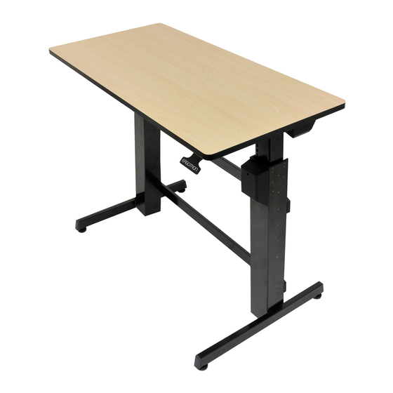
- Page 1 WorkFit-D < 65 lbs. (29.5 kg) 888-24-205-G-01 rev. C • 09/12 1 of 12...
-
Page 2: Hazard Symbols Review
WARNING WARNING! TIPPING HAZARD! When mounting accessories to the IMPACT HAZARD WorkFit-D, they must stay within the foot print. Do not mount accessories past the front and rear worksurface! Failure to fol- low this warning may result in equipment damage and or personal injury. - Page 3 WARNING! Stop screws are pre-installed in this product to secure it in the compressed position during shipping and installation. DO NOT REMOVE THESE SCREWS UNTIL INSTRUCTED TO DO SO IN THESE INSTRUCTIONS. Make sure these screws are in place before starting installation. Failure to follow these instructions may cause lift engine to expand rapidly and may result in equipment damage and or personal injury.
-
Page 4: Tools Needed
Components # 12-14 Wood Screw M5 x 6 mm M2.9 x 8 mm Tools Needed 14mm 1/4” 888-24-205-G-01 rev. C • 09/12 4 of 12... -
Page 5: Setup Steps
Set-up Steps Front Edge of Worksurface Place the worksurface on a clean fl oor with the top side facing down. Carefully position the leg with the hand brake on the right end of the worksurface. Place the other leg on the left end. Rear Edge of Worksurface NOTE: The brake cable is attached to both legs. - Page 6 WARNING Set-up Steps Keep Brake Cables Away from Sync Rod and Crossbars During Installation! Failure to keep the brake cables away from Set the left leg (without sync rod and crossbars may restrict lift motion and may cause equipment damage hand brake) upright on or personal injury! Refer to instruction manual for more information.
- Page 7 Set-up Steps Capture the brake cable in the cable clip as illustrated, then use a Phillips screwdriver to attach M2.9 x 8 mm the cable clips to bottom of work surface with the provided M2.9 x 8 mm screws. WARNING Keep Brake Cables Away from Sync Rod and Crossbars During Installation!
- Page 8 Set-up Steps Set the desk upright onto its legs. CAUTION! LIFT HAZARD! Two persons are required for this step. Failure to follow this warning may result in equipment damage and or personal injury. Adjust the riser on each leg and check with a level to make sure the work surface is even.
- Page 9 Set-up Steps Install all equipment before removing the 4 brake stop screws. CAUTION! Make sure you leave 20” (508mm) of slack in all cables to allow the worksurface to raise up it’s full 20” (508mm). Failure to allow enough slack in cables may cause cables to get pulled, equipment to fall off desk and may result in product damage and or personal injury.
- Page 10 40-60 revolutions per leg). Failure to heed this warning may result in serious personal injury or property damage! For More information and instructions visit www.ergotron.com or contact Ergotron Customer Care at 1-800-888-8458 826-463-00 888-24-205-G-01 rev. C • 09/12 10 of 12...
- Page 11 Adjustment Step Release the hand brake (on the right leg) and move the worksurface up to highest level. Push aside the cover located behind each leg to access the adjustment point. Maintain equal amount of tension on both legs by alternating the tension adjustment from one leg to the other using a 14mm socket wrench.
- Page 12 Set Your Workstation to Work For YOU! Confi gure su estación de trabajo para que trabaje para USTED. Ajustez votre station de travail en fonction de VOS besoins ! Richten Sie Ihren Arbeitsplatz so ein, dass er für SIE arbeitet! Stel uw werkstation zo in dat het voor U werkt! Approntare la stazione di lavoro nella posizione ergonomica ottimale.
Need help?
Do you have a question about the WorkFit-D and is the answer not in the manual?
Questions and answers