Advertisement
Quick Links
For the latest User Installation Guide please visit: www.ergotron.com
User's Guide - English
Guía del usuario - Español
Manuel de l'utilisateur - Français
Gebruikersgids - Deutsch
Benutzerhandbuch - Nederlands
Guida per l'utente - Italiano
Användarhandbok - svenska
ユーザーガイド : 日本語
用户指南 : 汉语
-
-
-G-
rev C • /
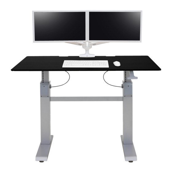
WORKFIT-DL
" (
mm)
Total Weight Capacity
Worksurface size
"x
" (
x cm)
"x
" (
x cm)
Cable Tray Weight Capacity:
lbs. (
CAUTION: DO NOT EXCEED
MAXIMUM LISTED WEIGHT
CAPACITY. SERIOUS INJURY OR
PROPERTY DAMAGE MAY OCCUR!
User's Guide
:
(includes Cable Tray)
lbs. (
kg)
lbs. (
kg)
kg)
Includes
Constant Force™
Technology
of
Advertisement

Related Manuals for Ergotron WORKFIT-DL


Summary of Contents for Ergotron WORKFIT-DL
- Page 1 " ( CAUTION: DO NOT EXCEED MAXIMUM LISTED WEIGHT CAPACITY. SERIOUS INJURY OR PROPERTY DAMAGE MAY OCCUR! For the latest User Installation Guide please visit: www.ergotron.com User's Guide - English Guía del usuario - Español Includes Manuel de l’utilisateur - Français Constant Force™...
- Page 2 Refer to installation manual for instructions on installing stop screws. Failure to heed this warning may result in serious personal injury or property damage! For More information and instructions visit www.ergotron.com or contact Ergotron Customer Care at 1-800-888-8458 826-901-00 rev C • /...
- Page 3 Safety WARNING! Stop screws are pre-installed in this product to secure it in the compressed position during shipping and installation DO NOT REMOVE THESE SCREWS UNTIL INSTRUCTED TO DO SO IN THESE INSTRUCTIONS Make sure these screws are in place before starting installation Failure to follow these instructions may cause li engine to expand rapidly and may result in equipment damage and or personal injury If any of the stop screws are not installed in these locations contact customer care before continuing with installation...
-
Page 4: Tools Needed
Components x / " M x mm Wood Screw / " " " Tools Needed 14mm 14mm rev C • /... - Page 5 NOTE: The brake cable is a ached to both legs. Take care when removing the legs from the packaging to avoid damaging or pulling the brake cable from the legs. Place the worksurface on a clean fl oor with the top side facing down Carefully position the leg with the hand brake on the side of the worksurface with the brake mounting holes and the other leg on the other side of the worksurface Rear Edge of Worksurface...
- Page 6 A ach cable channel x / " Wood Screw / " " " rev C • /...
-
Page 7: Wood Screw
Loosely a ach the leg with the brake handle to the worksurface NOTE: Do not fully insert the screws into the worksurface at this time. Leave approximately 1/8” space. x / " Wood Screw / " " " rev C • /... - Page 8 A ach the sync rod to the leg a ached to the worksurface WARNING WARNING! Keep Brake Cables Away from Sync Rod and Crossbars During Installation! Failure to keep the brake cables away from sync rod and crossbars may restrict li motion and may cause equipment damage or personal injury! Refer to instruction manual for more information.
- Page 9 Place the other leg on the worksurface and a ach the sync rod to it WARNING WARNING! Keep Brake Cables Away from Sync Rod and Crossbars During Installation! Failure to keep the brake cables away from sync rod and crossbars may restrict li motion and may cause equipment damage or personal injury! Refer to instruction manual for more information.
- Page 10 Loosely a ach the other leg to the worksurface NOTE: Do not fully insert the screws into the worksurface at this time. Leave approximately 1/8” space. x / " Wood Screw / " " " rev C • /...
- Page 11 A ach crossbar Make sure the brake cables don’t loop around the crossbars Tighten the screws slightly one at a time and repeat to ensure that the tension on every screw is equal NOTE: Do not overtighten screws. overtightening screws may result in stripping the holes and may cause the installation to be unsafe.
- Page 12 Tighten all the screws a aching legs to worksurface / " " " rev C • /...
- Page 13 A ach li brake to worksurface x / " Wood Screw rev C • /...
- Page 14 Insert brake cable into cable clips and a ach to worksurface x / " Wood Screw / " " " rev C • /...
- Page 15 A ach brake cable to legs using cable ties NOTE: Leave as much slack in cable as possible between the cable tie and the leg to allow desk top to raise up unrestricted. Failure to follow this may result in equipment damage. NOTE: Leave as li le slack in cable as possible between this cable tie and the brake release lever.
- Page 16 A ach the feet to the legs Front Edge of Worksurface Rear Edge of Worksurface rev C • /...
- Page 17 Set the desk upright onto its legs CAUTION! LIFT HAZARD! Two persons are required for this step Failure to follow this warning may result in equipment damage and or personal injury rev C • /...
- Page 18 Remove the brake stop screws before installing equipment Remove the stop screws from the legs then the stop screws from the brake to allow the worksurface to raise and lower IMPORTANT! Save these stop screws and instructions Install stop screws when shipping or storing this product Failure to follow these instructions may cause li engine to expand rapidly and may result in equipment damage and or personal injury rev C •...
- Page 19 A er you remove the brake stop screws release the hand brake on the right leg and move the worksurface up to highest level Install all equipment CAUTION! Make sure you leave ” of slack in all equipment cables to allow the worksurface to raise up it’s full ”...
- Page 20 Failure to heed this warning may result in serious personal injury or property damage! For More information and instructions visit www.ergotron.com or contact Ergotron Customer Care at 1-800-888-8458 826-901-00 WARNING! DO NOT tip desk over to adjust Only perform adjustment while desk is upright Failure to follow...
- Page 21 Adjustment Step On the back of each leg push in the adjustment doors to access the adjustment bolts NOTE The covers on the legs will not open unless the worksurface has been li ed to it’s full height The worksurface will not lower unless the covers have been completely closed Use either a socket drill or a socket wrench to adjust the bolts A socket drill is recommended due to the adjustment bolts needing many turns before noticing a diff...
- Page 22 Adjust the riser on each leg and check with a level to make sure the work surface is even Spin Le to Raise Spin Right to Lower Your Installation is Complete The following steps are for shipping or storing your cart rev C •...
-
Page 23: Appendix A - Minimize Li Tension
APPENDIX A - Minimize Li Tension WARNING Before removing mounted equipment monitor arm stand CPU etc from desk or to prepare for shipping or storing the desk it is extremely important to minimize the li tension Failure to follow these instructions may cause li engine to expand rapidly and may result in equipment damage and or personal injury WARNING! DO NOT tip desk over to adjust Only perform adjustment while desk is upright Failure to follow these instructions may cause the li engine to expand rapidly and may result in equipment damage... -
Page 24: Appendix B - Inserting Stop Screws
APPENDIX B - Inserting Stop Screws WARNING Before shipping or storing the desk or in cases where the desk is placed on it’s back or side* it is extremely important that the stop screws be re-inserted Failure to follow these instructions may cause li engine to expand rapidly and may result in equipment damage and or personal injury Follow instructions in Appendix A to minimize li tension... - Page 25 • minutes every hours For Warranty visit: www.ergotron.com/warranty For Service visit: www.ergotron.com For local customer care phone numbers visit: h p://contact.ergotron.com NOTE: When contacting customer service, reference the serial number. © 2016 Ergotron, Inc. All rights reserved. rev C • /...
Need help?
Do you have a question about the WORKFIT-DL and is the answer not in the manual?
Questions and answers