Champion D-H1T Technical Manual
Door-type extended hood dishwasher
Hide thumbs
Also See for D-H1T:
- Specifications (4 pages) ,
- Technical manual (74 pages) ,
- Brochure & specs (7 pages)
Table of Contents
Advertisement
Quick Links
For machines beginning with
serial no. D3694 and above
March, 2004
P. O. Box 4149
Winston-Salem, North Carolina 27115-4149
336/661-1556
Fax: 336/661-1660
www.championindustries.com
Technical Manual
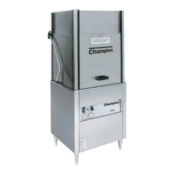
Door-Type
Extended Hood
Dishwasher
Model
D-HBTM5, D-HBTCM5
High Temperature
Extended Hood
with Built-in Booster
D-H1TM5, D-H1TCM5
High Temperature
Extended Hood
without Built-in Booster
Machine Serial No.
113492
P/N
Manual
2674 N. Service Road
Jordan Station, Ontario, Canada L0R 1S0
905/562-4195
Rev E
Fax: 905/562-4618
Advertisement
Table of Contents
Troubleshooting

Related Manuals for Champion D-H1T


Summary of Contents for Champion D-H1T
- Page 1 D3694 and above March, 2004 P. O. Box 4149 Winston-Salem, North Carolina 27115-4149 336/661-1556 Fax: 336/661-1660 Technical Manual Door-Type Extended Hood Dishwasher Machine Serial No. Manual www.championindustries.com Model D-HBTM5, D-HBTCM5 High Temperature Extended Hood with Built-in Booster D-H1TM5, D-H1TCM5...
- Page 2 Note: When calling to order parts, be sure to have the model number, serial number, voltage and phase of your machine, along with your customer account number. Machine Data Plate with Machine Model & Serial Number located on the front panel. COPYRIGHT ©2004 by Champion Industries, Inc. Serial Number Phone Phone Champion, Canada Phone:...
- Page 3 Revision History Revision Revised Date Pages 07/01/02 10/18/02 10/18/02 11-15 10/18/02 13, 15, 17, 24 10/18/02 10/18/02 35, 37 10/24/02 44, 45 10/24/02 10/24/02 10/24/02 54,55 10/24/02 60, 61 10/24/02 12/18/02 2/5/03 49,61 2/5/03 1/29/04 2/3/04 52-53 2/3/04 3/5/04 3/5/04 Serial Number Effectivity D3694...
-
Page 4: Table Of Contents
Figure 4 – Main Terminal Block ... 6 Figure 5 – Hot Water Connection (D-HBT Only) ... 7 Figure 6 – Hot Water Connection (D-H1T Only) ... 7 Figure 7 – Chemical Dispenser Signal Terminal Block... 9 Figure 8 – Chemical Signal Connection Points ... 9 Figure 9 –... - Page 5 Figure 18 – Pump Seal Replacement ...30 Figure 19 – Panels ...32 Figure 20 – Doors, Guides, & Stops (D-HBT, D-H1T) ...34 Figure 21 – Doors, Guides & Stops (Corner Model Only) (D-HBTC/DH1TC) ...36 Figure 22 – Door Handle, Spring Assembly and Safety Switch...38 Figure 23A –...
-
Page 6: Limited Warranty
United States and Canada to be free from defects in material and workmanship for a period of one (1) year after the date of installation or fifteen (15) months after the date of shipment by Champion, whichever occurs first. -
Page 7: Introduction
Welcome to Champion... and thank you for allowing us to take care of your dishwashing needs. This manual covers the door-type dishwasher, Model D-HBT, D-H1T, D-HBTC, D-H1TC. Your machine was completely assembled, inspected, and thoroughly tested at our factory before it was shipped to your installation site. -
Page 8: Model Number
Model Numbers D-HBT, D-HBTC, D-H1T, D-H1TC The D-HBT, D-HBTC models are high temperature (180˚F/82˚C rinse) sanitizing model with booster. The D-H1T, D-H1TC models are high temperature (180˚F/82˚C rinse) sanitizing models. Standard Equipment includes: D-HBT, D-HBTC, D-H1T, DH1TC • Automatic tank fill and start •... -
Page 9: Electrical Power Requirements
Electrical Power Requirements: Electric Heat/Electric Booster Model Voltage Booster Rise (D-HBT Only) D-H1T 208/60/1 — D-H1T 220/60/1 — D-H1T 230/60/1 — D-H1T 240/60/1 — D-H1T 208/60/3 — D-H1T 220/60/3 — D-H1T 230/60/3 — D-H1T 240/60/3 — D-H1T 380/60/3 — D-H1T 415/60/3 —... -
Page 10: Installation
If damage is found, save the packing material and con- tact the carrier immediately. 2. Remove the dishwasher from the skid. Move the machine to its permanent location. 3. Level the machine (if required) by placing a level on the top of the machine and adjusting the feet. -
Page 11: Electrical Connections
Electrical and grounding connections must comply with all applicable Electrical Codes. WARNING: When working on the dishwasher, discon- nect the electric service and place a tag at the disconnect switch to indicate work is being done on that circuit. 1. A qualified electrician must compare the... -
Page 12: Figure 3 Hinged Control Panel
The main terminal block is located on the side of the front right post of the dishwasher. Figure 3 Hinged Control Panel Electrical Power Connection Figure 4... -
Page 13: Plumbing Connections
(Min./Max. flow pressure 20-22 PSI/138-151.8 kPa) D-HBT with built-in 70˚ rise electric booster (Minimum 110˚F/43˚C) (Min./Max. flow pressure 20-22 PSI/138-151.8 kPa) D-H1T without built-in booster (Minimum 180˚F/70˚C) (Min./Max. flow pressure 20-22 PSI/138-151.8 kPa) Refer to Figs. 5 and 6 8-7/8"... -
Page 14: Drain Connections
2. The maximum drain flow rate is 15 gallons/min-56.8 liters/min. 3. Drain height for all models must not exceed 8-7/8" (225mm) above floor level. 4. The drain connection is made to the dishwasher from underneath the machine through an access hole in the machine base. -
Page 15: Chemical Connections
INSTALLATION (Cont.) Chemical Connections NOTE: Consult a qualified chemical supplier for your chemical needs. The detergent that you will need to use should be for automatic dishwashing machines. Refer to Fig. 7 1. A chemical signal terminal block is supplied for chemical dispensing equipment. -
Page 16: Figure 9 - Detergent Probe Injection Points, 1/2
A 1/4" NPT rinse aid injection point is provided in the final rinse manifold. Use a liquid rinse aid. The manifold is located on the top right side of the dishwasher. Models D-HBT and D-H1T do not require sanitizer. Figure 9 Detergent Probe Injection Points, 1/2"... -
Page 17: Initial Start-Up
1. Remove the white protective covering from the exterior of the machine. 2. Remove any foreign material from inside the machine. 3. Make sure dishwasher power switch is off. 4. Turn main water supply on. 5. Turn main power on at the main power service disconnect switch. -
Page 18: Water Temperature
Wait approximately 10 minutes for the wash tank water to reach operating temperature. The temperature should be a minimum of 150˚F/66˚C for (D-HBT, D-H1T). Prescrap the dishes. Load ware into the dishrack. Open the doors, insert the rack into the dishwasher. - Page 19 INITIAL START-UP Fully close the dishwasher doors. The dishwasher will begin the automatic cycle. Opening the doors anytime during the cycle will stop the dishwasher. Closing the doors will resume the automatic cycle where it left off. The cycle times are listed below:...
-
Page 20: Water Pressure
The final rinse water tempera- ture should be a minimum of 180˚F/82˚C for (D-HBT, D-H1T). The optimum final rinse temperature for (D-HBT, D-H1T) is 180-195˚F/82-91˚C. Check Final Rinse... - Page 21 The dishwasher will begin the cycle automatically. If the timed fill is activated due to a loss of water, the cycle will stop. When the dishwasher is full the auto- matic cycle will resume where it left off. The maximum total wash cycle time is 6 minutes.
- Page 22 Check all the plumbing for leaks. Also, check the drain plumbing for leaks and be sure that the drain will handle the drain water flow (15 gal/min-56.8 liters/min) from the dishwasher. After the drain and the plumbing connections are checked, turn off the dishwasher power switch. POWER...
-
Page 23: Operation Summary
6 minute = 5 minute 36 second wash 5. The final rinse temperature gauge should indicate a minimum of 180˚F/82˚C for D-HBT/ D-H1T. The optimum final rinse temperature range is between 180-195˚F/82-90˚C. 6. The water pressure gauge should indicate a flowing pressure of 20-22 PSI/138-151.8 kPa. -
Page 24: Cleaning
CLEANING SCHEDULE Every 2 Hours or After Each Meal Period 1. Drain the dishwasher. 2. Flush interior with fresh water. 3. Clean scrap screens and pump intake screen. 4. Clean spray arm nozzles. -
Page 25: Deliming Process
DELIMING Your dishwasher should be delimed regularly depending on the mineral content of your water. Inspect the machine interior for mineral deposits and use a deliming solution for the best clean- ing results. NOTE: Consult your chemical supplier for an appropriate deliming solution. -
Page 26: Troubleshooting
TROUBLESHOOTING Perform the seven checks listed below in the event that your dishwasher does not operate as expected. 1. All switches are ON 2. Wash and rinse nozzles are clean 3. Wash and rinse pipe assemblies are installed correctly 4. Scrap screens are properly positioned 5. - Page 27 138-151.8 kPa Clean Have installer change to proper size Clean or replace Check the booster (D-HBT, D-H1T) be sure the thermostat is set to maintain180˚F/82˚C temperature. Check valve to be sure it is clean and operating Check for proper setting or replace...
-
Page 28: Basic Service
Troubleshooting Schematics Champion places an electrical schematic in the control cabinet of every machine before it is shipped. Schematics are included at the back of this manual as well. Be aware that these schematics include options that may not apply to your machine. Options are enclosed in dashed lines with the words (IF USED) next to them on the schematic. -
Page 29: Figure 11 - Fuses
A 2-polefuse block is located on the machine base to protect the control circuit. To Replace a fuse: Turn the dishwasher main power switch off. Disconnect power to the machine at the main service disconnect switch. Replace the fuse. If the fuse blows again, Figure 11 DO NOT INCREASE THE FUSE SIZE. -
Page 30: Automatic Operation
SOLID STATE D-HBT AND D-H1T OPERATING INSTRUCTIONS Automatic Operation 1. Check that screens are clean and in place. 2. Turn on main power to the machine. 3. Flip machine control panel power switch to ON. 4. Close doors. • Machine pauses 4 seconds to check water level. - Page 31 • T8, marked “DOOR SW” (for the door safety switch). • T9, marked “FLOAT SW” (for the float switch). • T10, marked “EXT. WASH” (for the extended wash switch, not tested on D-HBT or D-H1T). 4. Check the results on the voltmeter: •...
-
Page 32: Figure 13 - Solid State Control Board
1.4 Testing Board Outputs After you have verified that the circuit board is receiving power (as explained above), then test the board outputs. There are 4 board outputs: • Wash Cycle. • Rinse Cycle. • Heaters. • In-Cycle Lamp. Perform the following steps to test a board output: 1. -
Page 33: Figure 14 Float Switch
Models D-HBT and D-H1T use a float switch and circuit board to control tank fill and tank heat. For Model D-HBT only, the built-in booster heat circuit is also con- trolled by the float switch. Operation: 1. When dishwasher main power switch is turned on (wash tank empty), the drain valve closes allowing cycle time to run for a minimum of 110 seconds to fill the tank. -
Page 34: Figure 16 Heater Element Wiring
ELECTRICAL SERVICE (Cont.) Heater Element Wiring – Booster Tank and Wash Tank Heater Elements Refer to the illustrations and follow the steps below to properly install terminal jumpers and to make line power connections to a replacement element. Step 1. Hold the element assembly with the calrod coils facing toward you. Step 2. -
Page 35: Figure 17 Pump Motor Wiring Diagrams
ELECTRICAL SERVICE (Cont.) Motor Connections — 1. Models D-HBT and D-H1T are available in either single phase or 3 phase voltages. 2. Motor rotation was set at the factory. For three phase machines, reversing the motor direction is done in the control cabinet by reversing the wires L1 and L2 on the disconnect side of the main electrical connection block. -
Page 36: Figure 18 Pump Seal Replacement
16. Reinstall impeller, and new flange gasket. Reinstall bolts. Reinstall drain plug. 17. Reinstall the pump/motor assembly and reconnect the pump hoses. 18. Fill the dishwasher with water. 19. Check motor rotation by bump starting motor. Correct motor shaft rotation is clockwise when viewing motor from the rear. -
Page 37: Replacement Parts
REPLACEMENT PARTS REPLACEMENT PARTS... -
Page 38: Figure 19 - Panels
REPLACEMENT PARTS Figure 19 - D-HBT/D-H1T Panels... - Page 39 Washer 13/16 x 1-13/16 Fiber ... 108417 Nut, Plastic... 100779 Screw, 1/4-20 x 5/8 Truss Head... 0504822 Screw, 8-32 x 1/2 Pan Head ... 100763 Screw, 10-32 x 1-1/4 Round Head ... 112587 Foot, Cast Grey ... D-HBT/D-H1T PANELS Part Description Qty.
-
Page 40: Figure 20 - Doors, Guides, & Stops (D-Hbt, D-H1T)
Figure 20 - DHB-T/DH1-T Doors, Guides, & Stops... - Page 41 DOORS, GUIDES, AND STOPS Fig 20 Part Item No. 100141 Nut, Grip 1/4-20 SST... 317345 Bracket, Door Catch ... 325921 Hook, Door Catch ... 108053 Plug, Corner Post ... 107970 Screw, 8/32 x 1" Filister Head... 112704 Door Guide, Side Door Left ... 112705 Door Guide, Side Door Right ...
-
Page 42: Figure 21 - Doors, Guides & Stops (Corner Model Only) (D-Hbtc/Dh1Tc)
REPLACEMENT PARTS Figure 21 - D-HBTC/D-H1TC Doors, Guides, & Stops (Corner Model Only) - Page 43 DOORS, GUIDES, AND STOPS Fig 21 Part Item No. 108053 Plug, Corner Post ... 107970 Screw 8-32 x 1 Filister Head ... 112704 Guide, Door Left ... 112705 Guide, Door Right ... 325633 Door, Side Upper ... 322788 Door, Lower Side (Prior to S/N D3863) ... 327252 Door, Side (After S/N D3864)...
-
Page 44: Figure 22 - Door Handle, Spring Assembly And Safety Switch
Figure 22 - D-HBT/D-H1T Door Handle, Spring Assembly, and Safety Switch... - Page 45 DOOR HANDLE, SPRING ASSEMBLY, AND SAFETY SWITCH Fig 22 Part Item No. 112723 Bolt 5/16-18 x 15 ... 108066 Spring, Extension... 107397 Block, Spring Hook ... 113757 Door Handle (Standard Machine)(Beginning with S/N D4185)... 112860 Door Handle (Corner Machine)(Prior to S/N D4184)..107437 Bolt M6 x 45MM Hex Head ...
-
Page 46: Figure 23A - Straight Track Assembly
Figure 23A – D-HBT/D-H1T Straight Track Assembly Figure 23B – D-HBT/D-H1T Corner Track Assembly... - Page 47 Screw (10-32 x 5/8 Flat Hd) ... 107966 Nut, Grip (10-32 w/Nylon Insert) ... 100073 Bolt (1/4 -20 x 1/2 Truss Head)... 106482 Washer, Lock ... 100003 Nut (1/4-20 Hex Hd) ... 0309473 Spacer... D-HBT/D-H1T Part Description D-HBT/D-H1T Part Description Qty. Qty.
-
Page 48: Figure 24 - Wash/Rinse Spray Piping
REPLACEMENT PARTS Figure 24 - D-HBT/D-H1T Wash/Rinse Spray Piping... - Page 49 Bolt 1/4-20 x 3/4 Hex Head... 107967 Nut, Grip 1/4-20... 109854 Gasket, Standpipe Wash... 100740 Bolt 5/16-18 x 1" Hex Head ... 106013 Washer, Lock 5/16 Split... 102376 Washer, Flat ... 100154 Nut, Plain 5/16-18 ... D-HBT/D-H1T Part Description Qty.
-
Page 50: Figure 25 - Wash/Rinse Spray Arms
REPLACEMENT PARTS AFTER S/N D3864 PRIOR TO S/N D3863 Figure 25 - D-HBT/D-H1T Wash/Rinse Spray Arms... - Page 51 0507446 Bearing, Wash Arm ... 0707453 is no longer available as a complete rinse arm assembly. Replacement nozzles and bearings are still available for that assembly. To replace the complete rinse arm assembly you will need to order 414111. D-HBT/D-H1T Part Description Qty.
-
Page 52: Figure 26 - Drain Assembly And Scrap Screens
Figure 26 - D-HBT/D-H1T Drain Assembly and Scrap Screens... - Page 53 Overflow Hose ... 324573 Overflow Flange Weldment ... 113047 Gasket, Drain Flange ... 106482 Washer, Lock 1/4 Split... 100003 Nut Plain 1/4-20 SST... 327283 Water Deflector (After S/N D3851) ... 327098 Support Drain Valve (Not Shown)... D-HBT/D-H1T Part Description Qty.
-
Page 54: Figure 27 - Wash Tank Heat And Thermostats
REPLACEMENT PARTS Figure 27 - D-HBT/D-H1T Wash Tank Heat and Thermostats... - Page 55 Heater 4.7KW 460V/3PH ... 113481 Heater 4.7KW 575V/3PH ... 100007 Screw 10-32 x 3/8 Truss Head... 107966 Nut, Grip 10-32 W/Nylon Insert ... 111092 Float Switch ... 104882 Washer ... 107089 Nut, Jam, 1/2-13... 111151 C-Clip Float Switch ... D-HBT/D-H1T Part Description Qty.
-
Page 56: Figure 28 - Electric Booster And Thermostats
REPLACEMENT PARTS Figure 28 - D-HBT Only Electric Booster and Thermostats... - Page 57 ELECTRIC BOOSTER AND THERMOSTATS Fig. 28 Part Item No. 100740 Bolt 5/16-18 x 1 Hex Head ... 102376 Washer, Flat 5/16 x 3/4 x 1/16... 108954 Nut, Grip 6-32 W/Insert... 110562 Thermostat, High Limit ... 110563 Compound, Heat Sink ... A/R 109069 Thermostat, Booster...
-
Page 58: Figure 29 - Lower Fill Piping Assembly (D-Hbt Only)
REPLACEMENT PARTS TO UPPER PIPING CUSTOMER WATER INLET Figure 29 - D-HBT Only Lower Fill Piping Assembly... - Page 59 LOWER FILL PIPING ASSEMBLY Fig. 29 Part Item No. 107550 Valve, Pressure Red 3/4" ... 102444 Street Ell 3/4" NPT Brass ... 102651 Nipple 3/4" x 2" Brass ... 111437 Valve 3/4" NPT Hot Water ... 100184 Nipple 3/4" NPT ... 102525 Tee 3/4"...
-
Page 60: Figure 30 - Upper Fill Piping Assembly (D-Hbt/D-H1T)
REPLACEMENT PARTS WATER IN FROM LOWER PIPING Figure 30 - D-HBT/D-H1T Upper Fill Piping Assembly... - Page 61 Nipple, 3/4" NPT x 2-1/2" Brass ... 104682 Thermometer 1/2" NPT ... 102521 Tee 3/4" NPT ... 102505 Plug 3/4 NPT Brass ... 113223 Repair Kit 3/4" Vacuum Breaker ... 102392 Bushing, Reducing 3/4"NPT x 1/2" Brass (After S/N D3700) ... D-HBT/D-H1T Part Description Qty.
-
Page 62: Figure 31 - Lower Fill Piping Assembly (D-H1T Only)
REPLACEMENT PARTS TO UPPER PIPING CUSTOMER WATER IN Figure 31 - D-H1T Only Lower Fill Piping Assembly... - Page 63 Needle, Valve 1/4" MPT Brass ... 107065 Adapter, 1/4"OD x 1/4 MPT Plastic ... 107928 Tubing, High Density... 111100 Elbow, Female 1/4" OD x 1/8 NPT... 109812 Gauge, Pressure 0-100 PSI ... 109765 Overlay, Gauge ... D-HBT/D-H1T Part Description Qty.
-
Page 64: Figure 32 - Pump Assembly
REPLACEMENT PARTS Figure 32 - D-HBT/D-H1T Pump Assembly... - Page 65 Kit, Pump (Includes 16, 18, 20, 23, 24) ... — 452281 Pump, Motor Assembly Complete 2HP (208-240V/460V/60/3PH)... — 452282 Pump, Motor Assembly Complete 2HP (115V/208-240V/60/1PH)... — 452283 Pump, Motor Assembly Complete 2HP (575V/60/3PH) ... D-HBT/D-H1T PUMP ASSEMBLY Part Description Qty.
-
Page 66: Figure 33 - Control Panel And Gauges
P/N 108391 POWER CYCLE WASH TEMPERTURE RINSE PRESSURE CHAMPION INDUSTRIES, INC. WINSTON-SALEM, NC MODEL W P/N 108391 Figure 33 - D-HBT/D-H1T Control Panel and Gauges 1 MIN 2 MIN 4 MIN 6 MIN 9 10 1 MIN 2 MIN 3 MIN... - Page 67 Gauge, Pressure 0-100 PSI ... 109756 Overlay, 20-30 PSI... 113051 Label, Panel Overlay DH-T/TC (Prior to S/N D3863) ... 113525 Label Panel Overlay (After S/N D3864) ... 113567 Label Panel Overlay Corner Model (After S/N D3864) ... D-HBT/D-H1T Part Description Qty.
-
Page 68: Figure 34 - Control Cabinet
REPLACEMENT PARTS Figure 34 - D-HBT/D-H1T Control Cabinet... - Page 69 Fuse, .5A, 600V (ATDR) 480V/3PH... 112887 Fuse, .5A, 600V (ATDR) 575V/3PH... 106402 Block, Fuse (2 Pole) (115V Only)... 107289 Fuse, 2.5A, 250V (ATDR) 115V Only ... — 103310 Wire Lug, Ground (Not Shown) ... D-HBT/D-H1T CONTROL CABINET Part Description Qty. 380-415V/3...
-
Page 70: Figure 35 - Dishracks And Prv
REPLACEMENT PARTS Figure 35 - Dishracks and PRV... - Page 71 Fig. 35 Part Item No. 101273 Rack (Flat Bottom) ... 101285 Rack (Peg) ... 112387 Line Strainer/PRV Combo ... 113281 Rack, Sheet Pan (Not Shown) ... DISHRACKS AND PRV Part Description Qty.
-
Page 72: Appendix A – Drain Valve/Timer Circuit
APPENDIX A DRAIN VALVE/TIMER CIRCUIT Models D-HBT and D-H1T use a drain circuit consisting of a 3cr relay, 10 minute timer, and a drain valve. OPERATION: 1) When the power switch is pushed to the OFF position, the 3CR relay coil is then energized, closing the 3CR contacts. -
Page 73: Electrical Schematic
REPLACEMENT PARTS ELECTRICAL SCHEMATICS... - Page 74 NOTE 1: IF SUPPLY VOLTAGE IS 115V, T1 IS NOT USED. WIRES DIAGRAM STATE #1 AND 2 ARE CONNECTED TO THE FUSE BLOCK IN PLACE OF L1 L2 L3 POWER OFF WIRES #39 AND 40. DOORS CLOSED TANKS EMPTY NOTE 2: DS1 NOT USED ON CORNER MACHINE MODELS. ON SINGLE PHASE END OF CYCLE MACHINES OMIT L3.