Sign In
Upload
Download
Table of Contents
Contents
Add to my manuals
Delete from my manuals
Share
URL of this page:
HTML Link:
Bookmark this page
Add
Manual will be automatically added to "My Manuals"
Print this page
×
Bookmark added
×
Added to my manuals
Manuals
Brands
Thermaltake Manuals
Computer Accessories
Armor-VA8000SWA
User manual
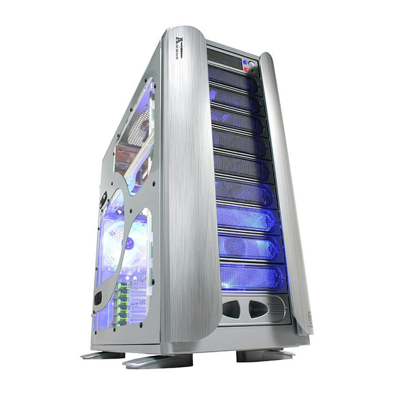
Thermaltake Armor-VA8000SWA User Manual
Case type super tower
Hide thumbs
1
Table Of Contents
2
3
4
5
6
7
8
9
10
11
12
13
14
15
page
of
15
Go
/
15
Contents
Table of Contents
Bookmarks
Table of Contents
Table of Contents
Chapter1 Product Introduction
Specification
Chapter2 Case Mechanical Operation
How to Open the Side Panel
Installing 5.25" Device
Installing 3.5" HDD
Removable 12Cm Fan Cage with 3HDD
To 3.5" Drive Tray Device Installation
Installing 3.5" Device to Drive Tray with Power Button
Installing Power Supply
Installing the Fan on Top of the Case
How to Remove the Fan & Fan Holder
Air Cooling System
BTX Upgraded Kits
PCI Slot Tool-Free Function Operation
Chapter3 Motherboard & Leads Installation
Motherboard Installation
Case LED Connections
USB2.0 & IEEE1394 Firewire Connection
Ear & MIC Connections
Chapter4 Other
Silent Purepower Power Supply (Optional)
Advertisement
Quick Links
1
Specification
2
How to Open the Side Panel
3
Removable 12Cm Fan Cage with 3Hdd
4
Installing Power Supply
5
Installing the Fan on Top of the Case
6
Air Cooling System
7
Motherboard Installation
8
Case Led Connections
Download this manual
User's Manual
User's Manual
C 2005 Thermaltake Technology Co.,Ltd. All Rights Reserved.
www.thermaltake.com
Table of
Contents
Previous
Page
Next
Page
1
2
3
4
5
Advertisement
Table of Contents
Need help?
Do you have a question about the Armor-VA8000SWA and is the answer not in the manual?
Ask a question
Questions and answers
Related Manuals for Thermaltake Armor-VA8000SWA
Computer Accessories Thermaltake Armor-VA8000BWS User Manual
Case type super tower (15 pages)
Computer Accessories Thermaltake Armor A30 VM70001W2Z User Manual
Mini case (12 pages)
Computer Accessories Thermaltake Chaser A31 User Manual
(13 pages)
Computer Accessories Thermaltake ARMOR A60 AMD VM200P Series User Manual
(17 pages)
Computer Accessories Thermaltake Armor VA8000BWS User Manual
Case type super tower (15 pages)
Computer Accessories Thermaltake VC3000SWA User Manual
Vc3000 series (28 pages)
Computer Accessories Thermaltake Commander MS-II VN900A1W2N User Manual
Mid tower computer case (13 pages)
Computer Accessories Thermaltake Lanbox Lite VF6000BWS User Manual
Lanbox lite vf6000 series (13 pages)
Computer Accessories Thermaltake The Tower 100 User Manual
(10 pages)
Computer Accessories Thermaltake Dokker VM6000 Series User Manual
Single bay docking station on top (12 pages)
Computer Accessories Thermaltake Versa N23 User Manual
Mid tower (10 pages)
Computer Accessories Thermaltake Soprano Dx VE7000 Series User Manual
Soprano dx ve7000 series (11 pages)
Computer Accessories Thermaltake Tsunami VA3000SNA User Manual
(12 pages)
Computer Accessories Thermaltake VIEW 27 User Manual
(12 pages)
Computer Accessories Thermaltake VP3000 Series User Manual
(13 pages)
Computer Accessories Thermaltake Core V41 User Manual
(13 pages)
This manual is also suitable for:
Armor-va8000bws
Armor va8000swa
Armor va8000bws
Table of Contents
Save PDF
Print
Rename the bookmark
Delete bookmark?
Delete from my manuals?
Login
Sign In
OR
Sign in with Facebook
Sign in with Google
Upload manual
Upload from disk
Upload from URL


Need help?
Do you have a question about the Armor-VA8000SWA and is the answer not in the manual?
Questions and answers