
Related Manuals for Thermaltake Soprano Dx VE7000 Series


Summary of Contents for Thermaltake Soprano Dx VE7000 Series
- Page 1 VE7000 Series User's Manual 2006 Thermaltake Technology Co., Ltd. All Rights Reserved. 2006.10 All other registered trademarks belong to their respective companies. www.thermaltake.com Tested To Comply With FCC Standards FOR HOME OR OFFICE USE...
-
Page 2: Chapter 1. Product Introduction
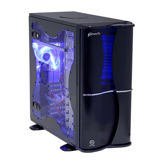
Chapter 1. Product Introduction Contents 1-1 Specifica tion Chapter 1. Product Introduction Specification Chapter 2. Case Mechanical Operation How to open the side panel Lock operation 5.25"device installation Model VE7000BNS VE700BWS VE7000SNA VE700SWA 3.5" device installation Case Type Middle Tower HDD installation Transparent Window Transparent Window... -
Page 3: Lock Opera Tion
Chapter 2. Case Mechanical Operation 2-1 How to open the side panel 2-2 Lock Opera tion To find out the side panel key in the back of the chassis, then Make sure the side open the side panel panel lock is opened. as shown below. -
Page 4: Device Installation
Squeeze and pull out-ward the tool-free clip 2-3 5.25" DEVICE INST ALLATION Unscrew the 5.25" drive bay metal cover. Place 5.25" device into the drive bay. Unscrew and remove the 5.25" plastic bay cover. Squeeze and push in-ward the tool-free clip. Finish installation... - Page 5 Release the tool-free clip as shown. 2-4 3.5" DEVICE INST ALLATION Remove the 3.5" drive bay metal cover. Insert the 3.5" drive into the front of chassis. Unscrew and remove the 3.5" plastic bay cover. Secure the 3.5" device as follow.
-
Page 6: Hdd Installation
2-5 HDD INST ALLATION Unscrew the thumb screw at the Screw up and fasten bottom side of the cage. HDD by thumb screws on the cage. Push the handle down and pull the cage out. Slide the cage into drive bay then screw up the thumb screw at the bottom side of the cage. -
Page 7: Pci Slot Tool-Free Usage
2-6 PCI SLOT TOOL-FREE USAGE 2-7 F an Fil ter remov al and cleaning Open the plastic clip then take off the Open the front panel, then press PCI bracket as follow. the fan filter. Take off the fan filter. Locate Graphic Card to the motherboard through fixing it on the space of PCI bracket and secure the Graphic Card as shown. -
Page 8: Case Led Connection
Chapter3 Motherboard & Leads Installation 3-1 Motherboard Inst allation 3-2 Case LED connection Each motherboard has different standoff layout. It is highly On the front of the case, you can find some LEDs and suggested that you refer to your motherboard's manual when switch leads (POWER SW*1, POWER LED*1, H.D.D. -
Page 9: Audio Connection
3-3 USB 2.0 3-4 Audio Connection Please refer to the following illustration of Audio USB connection connector and your motherboard user manual. Please select the motherboard which used AC'97 or HD Please consult your motherboard manual to find out the section of "USB connection". Audio (Azalia), (be aware of that your audio supports AC'97 or HD Audio (Azalia)) or it will damage your device(s). -
Page 10: Esat A Connection
Please tuck away this There are three main products of Thermaltake PSU, it is divided into wire and do not utilize this function. standard, VR and specialty power supply unit. Please refer to...
Need help?
Do you have a question about the Soprano Dx VE7000 Series and is the answer not in the manual?
Questions and answers