Rigol DP1116A User Manual
Programmable dc power supply
Hide thumbs
Also See for DP1116A:
- Installation manual (13 pages) ,
- Performance verification manual (49 pages)
Table of Contents
Advertisement
Quick Links
Download this manual
See also:
Installation Manual
Advertisement
Table of Contents

Related Manuals for Rigol DP1116A


Summary of Contents for Rigol DP1116A
- Page 1 RIGOL User’s Guide DP1116A Programmable DC Power Supply Mar. 2010 RIGOL Technologies, Inc.
-
Page 3: Trademark Information
Notices RIGOL products are protected by patent law in and outside of P.R.C. RIGOL Technologies, Inc. reserves the right to modify or change parts of or all the specifications and pricing policies at company’s sole decision. Information in this publication replaces all previously corresponding material. -
Page 4: Safety Notices
Do Not Operate Without Covers Do not operate the instrument with covers or panels removed. Use Proper Fuse Please use the specified fuses. Avoid Circuit or Wire Exposure User’s Guide for DP1116A... - Page 5 Do Not Operate With Suspected Failures If you suspect damage occurs to the instrument, have it inspected by qualified service personnel before further operations. Any maintenance, adjustment or replacement especially to circuits or accessories must be performed by RIGOL authorized personnel. Keep Well Ventilated Inadequate ventilation may cause an increase of temperature or damage to the device.
-
Page 6: Safety Terms And Symbols
CAUTION indicates a potential damage to the instrument or other property might occur. Symbols on the Product. These symbols may appear on the product: Hazardous Refer to Protective Chassis Test Instructions Earth Ground Ground Voltage Terminal User’s Guide for DP1116A... -
Page 7: Environment Considerations
Please contact your local authorities for disposal or recycling information. User’s Guide for DP1116A... -
Page 8: Dp1116A Overview
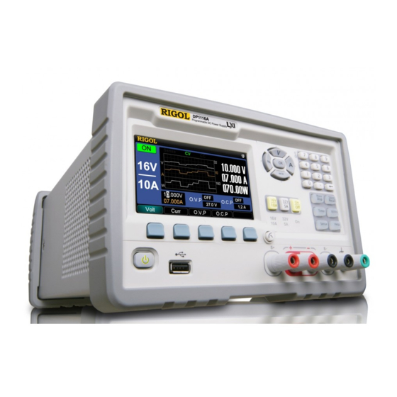
RIGOL DP1116A Overview RIGOL DP1116A is a single channel Programmable DC Power Supply with up to 160W power and two scales output. The excellent performance provided by this unit ensures a more pure and stable output from itself. Besides, the friendly, clear user interface and a variety of configuration interfaces as well as plenty of standard interfaces bring you more conveniences in actual use. -
Page 9: Structure Of This Document
This chapter gives the detailed information on function and operating methods of each key on the front panel. Chapter 3 Remote Control This chapter guide you how to control the DP1116A through the remote interfaces. Chapter 4 Troubleshooting This chapter offers some methods to help you solve the possible problems during operations. -
Page 10: Table Of Contents
Front/Rear Panel and User Interface ............1-3 Front Panel ..................1-3 Rear Panel ..................1-6 User Interface ..................1-7 First Use of DP1116A ................. 1-8 Power Requirements ................1-8 Power-On Check ................. 1-9 Output Inspection ................1-10 Display Mode ..................1-12 Chapter 2 Front Panel Reference ............ - Page 11 Chapter 4 Troubleshooting ..............4-1 Chapter 5 Specifications ................ 5-1 Chapter 6 Appendix ................6-1 Appendix A: Accessories ................6-1 Appendix B: Warranty ................6-2 Appendix C: General Care and Cleaning ............6-3 Index ......................1 User’s Guide for DP1116A...
-
Page 13: Chapter 1 Quick Start
Subjects in this chapter: General Inspection Front/Rear Panel and User Interface Front Panel Rear Panel User Interface First Use of DP1116A Power Requirements Power-On Output Inspection Display Mode User’s Guide for DP1116A... -
Page 14: General Inspection
RIGOL would not be responsible for free maintenance/rework or replacement of the unit. 2. Inspect the instrument In case of any damage, or defect, or failure, notify your RIGOL Sales Representative. 3. Check the accessories The accessories supplied with the instrument are listed in “Appendix A: Accessories”. -
Page 15: Front/Rear Panel And User Interface
Switch the display mode between General Display ⑥ Mode and Classic Display Mode Switch the channel scale, enable/disable the channel Scale key ⑦ output Output terminal Channel output connectors ⑧ Advanced Wave Disp: display the output signal with ⑨ function area waveforms User’s Guide for DP1116A... - Page 16 Help The indicator will be lighted after you enable the built-in help system. Front panel connectors ① ② ③ ④ ⑤ Name Explanations Connect as a “main unit” with an external USB device USB Host ① such as USB flash devices. User’s Guide for DP1116A...
- Page 17 This terminal is connected with the chassis and ground Earth terminal wire (grounded through the power cord) and can be ④ used as an additional ground terminal for other devices when the instrument is power on. User’s Guide for DP1116A...
-
Page 18: Rear Panel
Connect as a “slave device” with an external USB ⑥ device. Fuse Provided with two types of specifications: 250 V, ⑦ T4 A and 250 V, T2.5 A. Power switch Power on or cut off the power supply. ⑧ User’s Guide for DP1116A... -
Page 19: User Interface
*Remark: This area displays the actual output values of voltage, current and power as well as the identifier of “Sense”, “CC” (constant current) or “CV” (constant voltage). NOTE The DP1116A has three display modes and each mode has its own interface, for more details please refer to “Display Mode”. User’s Guide for DP1116A... -
Page 20: First Use Of Dp1116A
DP1116A. Power Requirements Use the power cord that is specifically designed for the DP1116A to connect the instrument and the AC power which delivers 100 V, 115 V, 220 V or 230 V, 50 Hz to 60 Hz. Users should select a voltage scale that meets the standards in their own country through the Power voltage selector (see Figure 1-2) at the rear panel and use an appropriate fuse. -
Page 21: Power-On Check
“System selftest is wrong, do you check the error?” on the interface. For more details about this test, press OK; or press Cancel to exit the message. User’s Guide for DP1116A... -
Page 22: Output Inspection
Constant Voltage output mode. Then check if the voltage in this scale can be set from 0 to 16.8 V (maximum rating). For how to enter the parameter please refer to “Parameter Input” (hereinafter inclusive). User’s Guide for DP1116A 1-10... -
Page 23: Current Output Inspection
terminals of 32V/5A. Press 32V/5A. Set the voltage to 32 V Press On/Off and inspect if the current in this scale can be set from 0 to 5.25 A (maximum rating). User’s Guide for DP1116A 1-11... -
Page 24: Display Mode
Chapter 1 Quick Start RIGOL Display Mode The DP1116A is designed with three display modes: General Display Mode, Waveform Display Mode and Classic Display Mode. The first two modes have their own colors (16V/10A: blue; 32V/5A: red). Users can choose an optimal display mode as required. - Page 25 (V) and current (A) as well as power (W), you can press to enter this mode regardless of the current display mode. Dial Needle Red line Green line Figure 1-7 Classic display mode User’s Guide for DP1116A 1-13...
- Page 26 “A” dials are setting values of O.V.P and O.C.P respectively. Turning on the O.V.P or O.C.P function will protect the circuit when the actual voltage or current reaches its setting value, and the red and green lines in the dials will be highlighted at the same time. User’s Guide for DP1116A 1-14...
-
Page 27: Chapter 2 Front Panel Reference
Constant Voltage Output Constant Current Output Overvoltage/Overcurrent Protection Timing Output Remote Voltage Sensing Store and Recall Utility Settings I/O Settings System Settings Calibrate Timer Setting Built-in Help Key Lock User’s Guide for DP1116A... -
Page 28: Parameter Input
Chapter 2 Front Panel Reference RIGOL Parameter Input The DP1116A contains two methods of parameter input: Pop-up box input and Direct input (modify). All parameters have to be entered by using the numeric keys or unit (direction) keys, see figures below: Figure 2-1 Unit (direction) keys (left) and numeric keys (right) 1. - Page 29 Increase or decrease the voltage or current value displayed at which the cursor is located by pressing the up (V) or down (mV) direction key. To move the cursor, pressing the left (mA) or right (A) direction key. User’s Guide for DP1116A...
- Page 30 To move the cursor in the soft keypad rapidly while you name a file for the storage, press and hold a direction key. User’s Guide for DP1116A...
-
Page 31: Constant Voltage Output
RIGOL Constant Voltage Output The DP1116A has two modes for power output: Constant Voltage output (CV) and Constant Current output (CC). The output mode of the channel is decided by a combination of the specified voltage and current as well as the load connected to the instrument. - Page 32 3. Scale selection: press 16V/10A at the front panel (characters below this key are highlighted). 4. Voltage setting: press Volt and set the voltage to 16 V. Figure 2-5 Voltage setting 5. Current setting: press Curr and set the current to 10 A. User’s Guide for DP1116A...
- Page 33 CC mode according to the present current value and reduce the output voltage proportionally. You can increase the setting value of the current at this moment in order to resume the CV output. User’s Guide for DP1116A...
-
Page 34: Constant Current Output
CV mode according to the present voltage value and reduce the output current proportionally. Increasing the setting value of the voltage at this moment will resume the CC output. User’s Guide for DP1116A... -
Page 35: Overvoltage/Overcurrent Protection
In order to keep the power output from exceeding the load rating and avoid damages to the load, the DP1116A was designed with the Overvoltage protection (O.V.P) and Overcurrent protection (O.C.P) functions. Users can set the parameters of the O.V.P and O.C.P optionally and enable or disable these functions as required;... -
Page 36: Parameter Setting
Press O.V.P continuously to switch the state of the O.V.P between ON and OFF. Please note the variety in the O.V.P input box as shown in figure below. O.V.P Status O.V.P Value Figure 2-7 O.V.P setting User’s Guide for DP1116A 2-10... - Page 37 The output will be automatically shut off once the output voltage exceeds the specified value of the O.V.P. The defaults of the O.V.P status and value are “OFF” and “35.2 V”, respectively. User’s Guide for DP1116A 2-11...
- Page 38 Press O.C.P continuously to switch the state of the O.C.P between ON and OFF. Please note the variety in the O.C.P input box as shown in figure below. O.C.P status O.C.P value Figure 2-8 O.C.P setting User’s Guide for DP1116A 2-12...
- Page 39 When the channel output is “OFF”, the O.C.P function is also disabled, but you can set its parameter. The output will be automatically disabled if the output current exceeds the O.C.P value. The defaults of the O.C.P status and value are “OFF” and “11A”, respectively. User’s Guide for DP1116A 2-13...
-
Page 40: Timing Output
Chapter 2 Front Panel Reference RIGOL Timing Output The DP1116A has Timing Output function. When you enable the timer, the instrument will output the pre-specified voltage, current (up to 100 groups) and simulate the running state of various kinds of power supply more really. - Page 41 See figure below, in Waveform display mode, the timing output can be seen from a waveform. Figure 2-10 Timing output (in Waveform display mode) See figure below, in Classic display mode, we can directly observe the switching process of the timing output parameters. User’s Guide for DP1116A 2-15...
- Page 42 Chapter 2 Front Panel Reference RIGOL Figure 2-11 Timing output (in Classic display mode) User’s Guide for DP1116A 2-16...
-
Page 43: Remote Voltage Sensing
RIGOL Remote Voltage Sensing As the DP1116A can provides 10 A output current and 160W output power, the voltage drop in the load leads must not be disregarded. In order to ensure the accuracy of the voltage drop while outputting a high current, the DP1116A was designed with a Sense (remote sense) function. - Page 44 Chapter 2 Front Panel Reference RIGOL Sense icon Figure 2-13 Sense status User’s Guide for DP1116A 2-18...
-
Page 45: Store And Recall
RIGOL Store and Recall The DP1116A supports operations with a USB flash device and local file storage, including: store, recall and delete the parameters about the voltage, current, O.V.P, O.C.P and other system setting parameters. Besides, you can store up to 4 groups of setting files (STATE1, STATE2, STATE3 or STATE4) or more into the USB flash device by using the function of Store/Recall. - Page 46 Press Save to store the file with a specified name and exit. File name entry box Chinese Character Soft display box keypad Figure 2-15 File name entry interface (Chinese) File name entry box Soft keypad Figure 2-16 File name entry interface (English) User’s Guide for DP1116A 2-20...
- Page 47 ② Switch to abc and enter a letter “N” from the soft keypad by using direction keys and then press OK. ③ Switch to ABC and enter a letter “e” from the soft keypad by using direction keys and then press OK. Then, enter “wfile” in the same way. User’s Guide for DP1116A 2-21...
- Page 48 Press Delete and Sure to delete this file. 5. Update The DP1116A supports for the system update through a USB device. After you select a desired file from the USB device, press this key to start the system update.
-
Page 49: Utility Settings
Set the parameters about the system, including Language, Power-on value, Screen brightness, Overtemperature, Beeper, Self-test and view the system information. Calibrate Enter the calibration interface. TimerSet Set the timing output parameters about the channel. Exit Exit the Utility function. User’s Guide for DP1116A 2-23... -
Page 50: I/O Settings
Chapter 2 Front Panel Reference RIGOL I/O Settings The DP1116A provides three communications interfaces: LAN, USB and GPIB. You can set them upon the I/O menu. Press I/O→LAN and enter the setting interface shown below: Figure 2-18 LAN setting Set the IP address: Choose the IP setting mode from “DHCP”, “Auto IP”... - Page 51 Default → OK to restore the LAN into the factory defaults. Figure 2-19 LAN defaults Press I/O → USB and enter the following interface, from where you can see the VISA address of the USB Device port on the rear panel (user-defined is unnecessary). User’s Guide for DP1116A 2-25...
- Page 52 Press I/O→GPIB and enter the interface shown below. The GPIB address ranges from 1 to 30. You can enter a desired value using the numeric keys and press OK to save. To delete the entered digits, press “←”. Figure 2-21 GPIB address setting User’s Guide for DP1116A 2-26...
-
Page 53: System Settings
Voltage: 0 Timer Current Current: 0 parameters CircleNum: 1 O.V.P value 35.2 V Language Last setting O.C.P value 11 A PowerOn Default Channel output brightness O.V.P function O.C.P function Beeper Waveform Web account Empty display User’s Guide for DP1116A 2-27... - Page 54 Figure 2-23 Screen brightness setting interface O.T.P The DP1116A provides two-level Overtemperature protection function. Pressing O.T.P can enable or disable the Overtemperature protection function. As shown in figure below, if you turn on the O.T.P, an icon will be shown on the status bar and the instrument will give you a prompt when the system temperature goes beyond the specified range.
- Page 55 Figure 2-25 Beeper setting User’s Guide for DP1116A 2-29...
- Page 56 Figure 2-26 Self-test menu If you press Result before any self-test, the results shown under this menu are from the Power-on self-test, see figure below: Figure 2-27 Self-test results User’s Guide for DP1116A 2-30...
- Page 57 Chapter 2 Front Panel Reference RIGOL SysInfo From this menu, you can view the related system information, see figure below: Figure 2-28 System information interface User’s Guide for DP1116A 2-31...
-
Page 58: Calibrate
Figure 2-29 Calibration password entry interface NOTE The instrument has been calibrated before leaving factory. We suggest users not to do a personal calibration. If the calibration must be done for your DP1116A, please contact RIGOL technical support. User’s Guide for DP1116A... -
Page 59: Timer Setting
Go to the next setting page. Go to the previous setting page. SelPage Go to the desired setting page. The total page is 20. Circle Set the circle parameters. Go to the next menu page. User’s Guide for DP1116A 2-33... - Page 60 When the output is opened, the instrument will start the first group of output and the left time “Left(s)” will be decreased gradually till 0; then the next group; etc. The output will stop after all user data has been outputted. User’s Guide for DP1116A 2-34...
-
Page 61: Built-In Help
“HELP” disappears from the status bar. To exit the help topic you are reading, press Exit. Figure 2-31 Help information User’s Guide for DP1116A 2-35... -
Page 62: Key Lock
Remote Mode In Remote mode, the power button and the number 7 key are locked automatically and an icon is shown on the screen. To exit the remote control, press and hold the number 7 key. User’s Guide for DP1116A 2-36... -
Page 63: Chapter 3 Remote Control
To control you DP1116A via web page, please follow the instructions below: 1. LAN Setting Use a Net cable to access your DP1116A into LAN, then press I/O → LAN to enter the setting interface of LAN (see figure below) and follow the “I/O Settings”... - Page 64 (1) Click “Network Status” and enter the network status interface as shown in figure below. From this interface, you can view the settings of TCP/IP and network hardware. Figure 3-3 Network status interface (2) Click “Network Settings” and enter the IP setting interface, see figure below: User’s Guide for DP1116A...
- Page 65 (the default user name and password are empty). To create a new password or modify the password that has already existed please refer to “(4)”. (3) Click “Help” and enter the help interface for the information about the instrument and network, see figure below: User’s Guide for DP1116A...
- Page 66 “Apply”, a hint like “Note: Your password setting successful” will be shown on the screen. Figure 3-6 Network security setting interface (5) Click “LXI” icon and directly enter the official website of the LXI union “http://www.lxistandard.org/”. User’s Guide for DP1116A...
-
Page 67: Command Control
“Agilent IO Libraries Suite” from Agilent (Agilent Technologies, Inc.) to control your DP1116A via remote interfaces by sending commands. The DP1116A supports communications with a PC through USB, LAN or GPIB bus. In the following part, we will introduce you how to use the associated Ultra Sigma software to control the DP1116A through various interfaces. - Page 68 1. By USB Please follow the steps below: (1) Connect the instruments Use a USB data cable to connect the USB Device port of your DP1116A to the USB Host of a PC. (2) Install the USB driver DP1116A is a USBTMC unit. After you connect it with the PC correctly, turn on the instrument (the instrument will automatically use the USB interface), a dialog appears on the PC screen and guide you to install the “USB Test and...
- Page 69 Figure 3-8 Available USB devices (5) Communication test Right click “DP1116A (USB0::0x1AB1::0x0E10::DP1A666666666::INSTR)” and select “Instrument Common RIGOL SCPI ControlPanel V1” to open the remote control panel and send commands or read the data, see figure below: Figure 3-9 Read and write commands through USB...
- Page 70 Figure 3-11 Available LAN resources (5) Communication test Right click “DP1116A (TCPIP::172.16.3.38::INSTR)” and select “Instrument Common RIGOL SCPI ControlPanel V1” to open the remote control panel and send commands or read the data, see figure below: User’s Guide for DP1116A...
- Page 71 Figure 3-12 Read and write commands through LAN (6) Load the LXI web page The DP1116A conforms to the LXI-C standards (Version 1.2). You can load the LXI web page through Ultra Sigma (right click the instrument name and select “LXI-Web”), from this page you can view the instrument information, including...
- Page 72 3. By GPIB Please follow the steps below: (1) Connect the instruments Use a GPIB cable to connect your DP1116A to a PC. (2) Set the GPIB address See “I/O Settings” in Chapter 2, select “GPIB” interface and configure its GPIB address.
- Page 73 (5) Communication test Right click the “DP1116A (GPIB0::25::INSTR) and select “Instrument Common RIGOL SCPI ControlPanel V1” to enter the remote control panel and send commands or read the data, see figure below: Figure 3-16 Read and write commands by GPIB User’s Guide for DP1116A...
-
Page 75: Chapter 4 Troubleshooting
(3) Disconnect the power cord and check if the Voltage Selector is in proper scale and a right fuse is used and in good condition. (4) If the error still exists, please contact RIGOL for help. Constant voltage output is abnormal: (1) Check if the maximum power from the selected scale can meet the load requirement. -
Page 77: Chapter 5 Specifications
1 mV/1 mA Meter 1 mV/1 mA Transient Response Time Less than 50 μs is spent on recovering the voltage within 15 mV when the output current changes from full load to half load or half to full. User’s Guide for DP1116A... -
Page 78: Command Processing Time
At high temperature: the output current drops to 50% at 55℃of maximum. Cooling Fan cooling Product Regulation CE, cTUVus Remarks: [1] Specifications are for one hour warm-up and at 25 ℃. [2] The maximum time required for regulating the corresponding output when received APPLy User’s Guide for DP1116A... - Page 79 Chapter 3 Remote Control RIGOL and SOURce commands. [3] The varieties of outputs within 8 hours when the instrument has been warmed up for 30 minutes and both the load circuit and environment temperatures are in constant conditions. User’s Guide for DP1116A...
-
Page 81: Chapter 6 Appendix
An Instruction 4 fuses (250 V / T2.5 A and 250 V / T4 A, 2 for each) 2 shorted devices Note: All the accessories can be ordered from your local RIGOL office. User’s Guide for DP1116A... -
Page 82: Appendix B: Warranty
RIGOL Appendix B: Warranty RIGOL warrants that its mainframe and accessories of the product will be free from defects in materials and workmanship within the warranty period. If a product is proven to be defective within the warranty period, RIGOL guarantees the free replacement or repair of products which are approved defective. -
Page 83: Appendix C: General Care And Cleaning
To avoid damages to the instrument, do not expose them to liquids which have causticity. WARNING To avoid injury resulting from short circuit, make sure the instrument is completely dry before reconnecting it to a power source. User’s Guide for DP1116A... -
Page 85: Index
USB ........... 2-25 Load Regulation ......5-1 User Interface ......1-7 Mechanical ........5-2 Utility Settings ......2-23 Noise .......... 5-1 Voltage Programming Speed ..5-2 O.C.P ........2-12 Working Mode of Sense ....2-17 O.V.P ......... 2-10 User’s Guide for DP1116A...
Need help?
Do you have a question about the DP1116A and is the answer not in the manual?
Questions and answers