Rigol DP1308A Performance Verification Manual
Programmable linear dc power supply
Hide thumbs
Also See for DP1308A:
- User manual (67 pages) ,
- Service manual (50 pages) ,
- Installation manual (13 pages)

Related Manuals for Rigol DP1308A


Summary of Contents for Rigol DP1308A
- Page 1 RIGOL Performance Verification Manual DP1308A Programmable Linear DC Power Supply Feb. 2014 RIGOL Technologies, Inc.
-
Page 3: Guaranty And Declaration
Notices RIGOL products are protected by patent law in and outside of P.R.C. RIGOL reserves the right to modify or change parts of or all the specifications and pricing policies at company’s sole decision. Information in this publication replaces all previously corresponding material. -
Page 4: General Safety Summary
Do not operate the instrument with covers or panels removed. Do Not Insert Anything into the Holes of Fan. Do not insert anything into the holes of the fan to avoid damaging the instrument. Use Proper Fuse. Please use the specified fuses. DP1308A Performance Verification Manual... - Page 5 Do Not Operate With Suspected Failures. If you suspect damage occurs to the instrument, have it inspected by qualified service personnel before further operations. Any maintenance, adjustment or replacement especially to circuits or accessories must be performed by RIGOL authorized personnel. Keep Well Ventilation.
- Page 6 In order to avoid the anti-irrigation current which leads to the power control loop out of control and damages the powered device, this power supply can only provide power for the pure load without the current output function. DP1308A Performance Verification Manual...
-
Page 7: Allgemeine Sicherheits Informationen
Der Betrieb mit offenen oder entfernten Gehäuseteilen ist nicht zulässig. Nichts in entsprechende Öffnungen stecken (Lüfter z.B.) Passende Sicherung verwenden. Setzen Sie nur die spezifikationsgemäßen Sicherungen ein. Vermeiden Sie ungeschützte Verbindungen. Berühren Sie keine unisolierten Verbindungen oder Baugruppen, während das Gerät in Betrieb ist. DP1308A Performance Verification Manual... - Page 8 Wenn Sie am Gerät einen Defekt vermuten, sorgen Sie dafür, bevor Sie das Gerät wieder betreiben, dass eine Untersuchung durch qualifiziertes Kundendienstpersonal durchgeführt wird.Jedwede Wartung, Einstellarbeiten oder Austausch von Teilen am Gerät, sowie am Zubehör dürfen nur von RIGOL autorisiertem Personal durchgeführt werden. Belüftung sicherstellen.
-
Page 9: Document Overview
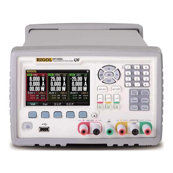
RIGOL Document Overview DP1308A is a high-performance programmable linear DC power supply with 80W triple outputs (+6V/5A, +25V/1A and -25V/1A). This manual introduces the DP1308A performance verification procedures which verify that DP1308A is operating normally and is within published specifications. -
Page 10: Table Of Contents
CC Linear Adjustment Rate (CC Source Effect) ........... 3-5 CC Ripple and Noise (Normal Mode)............3-7 CC Programming and Readback Accuracy ..........3-8 Appendix ....................1 Appendix A: Test Result Record Form ............1 Appendix B: Specifications ................4 DP1308A Performance Verification Manual VIII... -
Page 11: Chapter 1 Test Preparations
Chapter 1 Test Preparations This chapter introduces the test preparations as well as the recommended test devices. Topics of this chapter: Self-test and Warm-up Recommended Test Devices Voltage and Current Values Test Result Record DP1308A Performance Verification Manual... -
Page 12: Self-Test And Warm-Up
If the self-test fails, make sure that the problems are found and solved and the instrument passes the self-test before performing the performance verification test. Warm-up Warm the instrument up for at least 30 minutes before performing the performance verification test. DP1308A Performance Verification Manual... -
Page 13: Recommended Test Devices
Recommended Test Devices Please use the recommended test devices in Table 1-1 to test the performance specifications of DP1308A. If these devices are not present, use devices that fulfill the “Performance Requirement” in the table below instead. Table 1-1 Recommended Test Devices... -
Page 14: Voltage And Current Values
Table 1-2 lists the rated output values and maximum output values of the voltage and current of each channel. Table 1-2 Voltage and current values of each channel of DP1308A Rated Output Output... -
Page 15: Chapter 2 Constant Voltage Tests
Chapter 2 Constant Voltage Tests RIGOL Chapter 2 Constant Voltage Tests This chapter introduces how to test the specifications of DP1308A under CV mode. Topics of this chapter: Preparation CV Load Adjustment Rate (CV Load Effect) CV Linear Adjustment Rate (CV Source Effect) ... -
Page 16: Preparation
Before the test, select the appropriate voltage (for the voltages supported by DP1308A, refer to Table 2-1) via the “voltage selector” at the rear panel of the power supply according to the AC line voltage of your nation. Connect the device recommended in Recommended Test Devices according to the figure below under normal temperature (about 25℃). -
Page 17: Cv Load Adjustment Rate (Cv Load Effect)
Rated Output Voltage Turn off DP1308A. Connect DP1308A, AC source, electronic load and multimeter according to Figure 2-1. Note that the measurement probe or clip of the multimeter must be connected to A in Figure 2-2. Turn on the AC source and set its voltage to the AC line voltage. - Page 18 RIGOL Chapter 2 Constant Voltage Tests Turn on DP1308A. Press +6V, +25V or -25V at the front panel to select the channel to be tested. Set the voltage and current of the channel to be tested according to Table 2-2. Press On/Off under the channel to be tested to enable power output.
-
Page 19: Cv Linear Adjustment Rate (Cv Source Effect)
Turn on the AC source and set its voltage to the AC line voltage. Turn on DP1308A and press +6V, +25V or -25V at the front panel to select the channel to be tested. Set the voltage and current of the channel to be tested according to Table 2-3. - Page 20 10. Repeat steps 1 to 9 to test the CV linear adjustment rates of the other two output channels. Table 2-3 Setting and specification of CV linear adjustment rate test Channel +6V/5A +25V/1A -25V/1A Voltage (V) Current (A) 5.25 1.05 1.05 Specification <0.01%+2mV DP1308A Performance Verification Manual...
-
Page 21: Cv Ripple And Noise
RMS or peak-to-peak noise. Turn off DP1308A. Connect DP1308A, AC source, resistive load (1.2Ω for +6V/5A channel; 25Ω for +25V/1A and -25V/1A channels) and oscilloscope according to... - Page 22 Turn on the AC source and set its voltage to the AC line voltage. Turn on DP1308A and press +6V, +25V or -25V at the front panel to select the channel to be tested. Set the voltage of the channel to be tested to the rated output value and the current to the maximum output value according to Table 2-4.
- Page 23 Chapter 2 Constant Voltage Tests RIGOL Table 2-4 Setting and specification of CV ripple and noise test Channel +6V/5A +25V/1A -25V/1A Voltage (V) Current (A) 5.25 1.05 1.05 Specification <350 uVrms/2 mVpp DP1308A Performance Verification Manual...
-
Page 24: Transient Response Time
Turn on the AC source and set its voltage to the AC line voltage. Turn on DP1308A and press +6V, +25V or -25V at the front panel to select the channel to be tested. Set the voltage and current of the channel to be tested according to Table 2-5. - Page 25 +6V/5A +25V/1A -25V/1A Voltage (V) Current (A) 5.25 1.05 1.05 High Level: 5 High Level: 1 High Level: 1 Electronic Load Current (A) Low Level: 2.5 Low Level: 0.5 Low Level: 0.5 < Specification 50μs DP1308A Performance Verification Manual 2-11...
-
Page 26: Cv Programming And Readback Accuracy
Programming accuracy and readback accuracy verify the high accuracy and programmable performance of the power supply. Turn off DP1308A. Connect DP1308A, AC source and multimeter according to Figure 3-1. Turn on the AC source and set its voltage to the AC line voltage. - Page 27 Measure the CV programming accuracy and readback accuracy under rated output voltage. Turn on DP1308A. Execute the following operations via the remote interface (USB, LAN or GPIB): Send command to select the channel to be tested and set its voltage and current (according to the Table 2-7): APPLy P6V,6,5.25 (for +6V/5A channel)
-
Page 29: Chapter 3 Constant Current Tests
CC mode. Topics of this chapter: Preparation CC Load Adjustment Rate (CC Load Effect) CC Linear Adjustment Rate (CC Source Effect) CC Ripple and Noise (Normal Mode) CC Programming and Readback Accuracy DP1308A Performance Verification Manual... -
Page 30: Preparation
Multimeter/ Oscilloscope/ RMS Voltmeter Electronic AC Source DP1308A Load Figure 3-1 Test connection (CC) DP1308A Performance Verification Manual... -
Page 31: Cc Load Adjustment Rate (Cc Load Effect)
CC. 3. Turn on DP1308A and press +6V, +25V or -25V at the front panel to select the channel to be tested. Set the voltage and current of the channel to be tested according to Table 3-1. - Page 32 8. Repeat steps 1 to 7 to test the CC load adjustment rates of the other two output channels. Table 3-1 Setting and specification of CC load adjustment rate test Channel +6V/5A +25V/1A -25V/1A Voltage (V) 26.25 -26.25 Current (A) Specification <0.01%+250uA DP1308A Performance Verification Manual...
-
Page 33: Cc Linear Adjustment Rate (Cc Source Effect)
2. Turn on the AC source and set its voltage to the AC line voltage. 3. Turn on DP1308A and press +6V, +25V or -25V at the front panel to select the channel to be tested. Set the voltage and current of the channel to be tested according to Table 3-2. - Page 34 10. Repeat steps 1 to 9 to test the CC linear adjustment rates of the other two output channels. Table 3-2 Setting and specification of CC linear adjustment rate test Channel +6V/5A +25V/1A -25V/1A Voltage (V) 26.25 -26.25 Current (A) Electronic Load Voltage (V) Specification <0.01%+250uA DP1308A Performance Verification Manual...
-
Page 35: Cc Ripple And Noise (Normal Mode)
2. Turn on the AC source and set its voltage to the AC line voltage. 3. Turn on DP1308A and press +6V, +25V or -25V at the front panel to select the channel to be tested. Set the voltage and current of the channel under test according to Table 3-3. -
Page 36: Cc Programming And Readback Accuracy
Programming accuracy and readback accuracy verify the high accuracy and programmable performance of the power supply. 1. Turn off DP1308A. Connect DP1308A, AC source, current monitoring resistor (0.1Ω) and multimeter. 2. Turn on the AC source and set its voltage to the AC line voltage. - Page 37 4. Measure the programming accuracy and readback accuracy under rated output current. Turn on DP1308A. Execute the following operations via the remote interface (USB, LAN or GPIB): Send command to select the channel to be tested and set its voltage and...
-
Page 39: Appendix
Appendix RIGOL Appendix Appendix A: Test Result Record Form Performance Verification Test Record Form for RIGOL DP1308A Tested by: Date: +6V/5A +25V/1A -25V/1A Channel Channel Channel CV Load Adjustment Rate Specification <0.01%+2mV Output Voltage (No Load) U Output Voltage (Full Load) U... - Page 40 Specification <0.01%+250uA Short-circuit Current Full Load Current Calculation Result CC Linear Adjustment Rate Specification <0.01%+250uA Output Current (Undervoltage) U Output Current (Overvoltage) U Calculation Result CC Ripple and Noise (Normal Mode) Specification <2mArms <500uArms Measurement Value DP1308A Performance Verification Manual...
- Page 41 Appendix RIGOL CC Programming and Readback Accuracy Programming Specification 0.5mA 0.1mA Measurement Result (0A) Measurement Result (Rated Current) Readback Specification 0.5mA 0.1mA Measurement Result (0A) Measurement Result (Rated Current) DP1308A Performance Verification Manual...
-
Page 42: Appendix B: Specifications
Year Accuracy (25℃±5℃) ± (output percentage + offset) Voltage 0.1%+5mV 0.05%+20mV Programming Current 0.2%+10mA 0.15%+4mA Voltage 0.1%+5mV 0.05%+10mV Readback Current 0.2%+10mA 0.15%+4mA Resolution Programming 0.5mV/0.5mA 1.5mV/0.1mA Readback 0.5mV/0.5mA 1.5mV/0.1mA Electric Meter 1mV/1mA 10mV/1mA Transient Response Time DP1308A Performance Verification Manual... - Page 43 : The maximum time required for the output to change accordingly after receiving the APPLy and SOURce commands. Note : The variation of the output within 8 hours after 30-minute warm-up when the load circuit and environment temperature are constant. DP1308A Performance Verification Manual...
Need help?
Do you have a question about the DP1308A and is the answer not in the manual?
Questions and answers