
Related Manuals for Rigol DP831


Summary of Contents for Rigol DP831
- Page 1 User Guide DP800 Series Programmable Linear DC Power Supply Jun. 2021 RIGOL TECHNOLOGIES CO., LTD. GlobalTestSupply www. .com Find Quality Products Online at: sales@GlobalTestSupply.com...
-
Page 2: Guaranty And Declaration
Notices RIGOL products are covered by P.R.C. and foreign patents, issued and pending. RIGOL reserves the right to modify or change parts of or all the specifications and pricing policies at the company’s sole decision. Information in this publication replaces all previously released materials. -
Page 3: Safety Requirement
RIGOL Safety Requirement General Safety Summary Please review the following safety precautions carefully before putting the instrument into operation so as to avoid any personal injury or damage to the instrument and any product connected to it. To prevent potential hazards, please follow the instructions specified in this manual to use the instrument properly. - Page 4 Do Not Operate with Suspected Failures. If you suspect that any damage may occur to the instrument, have it inspected by RIGOL authorized personnel before further operations. Any maintenance, adjustment or replacement especially to circuits or accessories must be performed by RIGOL authorized personnel.
-
Page 5: Safety Notices And Symbols
RIGOL Safety Notices and Symbols Safety Notices in this Manual: WARNING Indicates a potentially hazardous situation or practice which, if not avoided, will result in serious injury or death. CAUTION Indicates a potentially hazardous situation or practice which, if not avoided, could result in damage to the product or loss of important data. -
Page 6: Care And Cleaning
RIGOL Care and Cleaning Care Do not store or leave the instrument where it may be exposed to direct sunlight for long periods of time. Cleaning Clean the instrument regularly according to its operating conditions. Disconnect the instrument from all power sources. -
Page 7: Environmental Considerations
RIGOL Environmental Considerations The following symbol indicates that this product complies with the requirements in WEEE Directive 2002/96/EC. Product End-of-Life Handling The equipment may contain substances that could be harmful to the environment or human health. To avoid the release of such substances into the environment and avoid harm to human health, we recommend you to recycle this product appropriately to ensure that most materials are reused or recycled properly. -
Page 8: Dp800 Series Overview
RIGOL DP800 Series Overview DP800 series is high-performance programmable linear DC power supply. DP800 series which provides clear user interface, superb performance specifications, various analysis functions as well as various communication interfaces can fulfill versatile test requirements. Main Features: User-friendly Design: 3.5-inch TFT display, displaying multiple parameters and states at the same time... - Page 9 RIGOL Support digital trigger (option) to realize digital trigger input and trigger output functions Support on-line analyzer (option) to perform on-line analysis of various statistic parameters Support monitor (option) to monitor the output according to the user-defined ...
-
Page 10: Document Overview
RIGOL Document Overview Chapter 1 Quick Start Introduce the appearance and dimensions, front panel, rear panel as well as user interface of DP800. In addition, it provides the detailed procedures of power connection, power-on inspection, and fuse replacement. Chapter 2 Front Panel Operations Introduce the function and operation method of each key on the front panel of DP800 in detail. - Page 11 Unless otherwise noted, this manual illustrates the functions and operation methods of DP800 series by taking DP832 as an example. Model Number of Channels Channel Output Voltage/Current DP832 30V/3A, 30V/3A, 5V/3A DP831 8V/5A, 30V/2A, -30V/2A DP822 20V/5A, 5V/16A DP821 60V/1A, 8V/10A DP813 Range1: 8V/20A;Range2: 20V/10A...
-
Page 12: Table Of Contents
RIGOL Contents Contents Guaranty and Declaration ................ I Safety Requirement ................II General Safety Summary ................II Safety Notices and Symbols ............... IV Allgemeine Sicherheits Informationen ............V Sicherheits Begriffe und Symbole .............. VII Care and Cleaning ................. VIII Environmental Considerations ..............IX DP800 Series Overview ................ - Page 13 RIGOL Contents Display Setting ..................2-41 Brightness ..................2-41 Contrast ..................2-41 RGB Luminance................2-41 Display Mode ................. 2-42 Display Theme ................2-42 User-defined Start-up Interface ............2-43 Store and Recall ................... 2-45 Browser ..................2-46 File Type..................2-46 Save ..................... 2-47 Read .....................
-
Page 14: Chapter 1 Quick Start
RIGOL Chapter 1 Quick Start Chapter 1 Quick Start The contents of this chapter are as follows: General Inspection Appearance and Dimensions Front Panel Rear Panel To Connect to Power Power-on Inspection To Replace the Fuse ... -
Page 15: General Inspection
The consigner or carrier shall be liable for the damage to the instrument resulting from shipment. RIGOL would not be responsible for free maintenance/rework or replacement of the instrument. 2. Inspect the instrument... -
Page 16: Appearance And Dimensions
RIGOL Chapter 1 Quick Start Appearance and Dimensions Figure 1-1 Front View Unit: mm Figure 1-2 Side View Unit: mm DP800 User Guide GlobalTestSupply www. .com Find Quality Products Online at: sales@GlobalTestSupply.com... -
Page 17: Front Panel
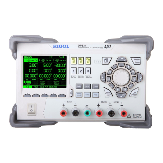
RIGOL Chapter 1 Quick Start Front Panel This section introduces the front panel of DP800 series by taking DP832 (as shown in the figure below) as an example. The differences of different models are introduced separately. Figure 1-3 DP832 Front Panel... - Page 18 RIGOL Chapter 1 Quick Start 1. LCD 3.5-inch TFT display. It is used to display the system parameter setting, system output state, menu items, prompt messages, etc. 2. Channel (Range) Selection and Output Switch For the multi-channel model, the function of this part is channel selection and output switch.
- Page 19 RIGOL Chapter 1 Quick Start Single-channel model (take DP811 as an example): Press this key to select 20V/10A range as the current range and you can set the parameters of the channel, such as voltage, current and overvoltage/overcurrent protection. Press this key to select 40V/5A range as the current range and you can set the parameters of the channel, such as voltage, current and overvoltage/overcurrent protection.
- Page 20 RIGOL Chapter 1 Quick Start the keys are used to enter the voltage units (V and mV) or the current units (A and mA). (2) Numeric Keyboard Ring-type numeric keyboard: include numbers 0-9 and the decimal point. Press the corresponding key to directly input the number or decimal point.
- Page 21 RIGOL Chapter 1 Quick Start 7. Output Terminals The output terminals of different models of DP800 series are different. DP832: DP822/DP821: 60V/1A 8V/10A DP813/DP811: Output (1) Channel output terminals: used to output the voltage and current of the channel. (2) Ground terminal: this terminal is connected to the instrument chassis and ground wire (the ground terminal of the power cord) and is in grounded state.
- Page 22 RIGOL Chapter 1 Quick Start Connection methods of the output terminal: Method 1: Connect the test lead to A of the output terminal. Method 2: Rotate the outer nut of the output terminal counterclockwise and connect the test lead to B of the output terminal; then, rotate the outer nut of the output terminal clockwise.
- Page 23 RIGOL Chapter 1 Quick Start Press this key to enter the system utility function setting interface. Users can set the remote interface parameters, system parameters and print parameters. Besides, users can also calibrate the instrument, view system information, define the recall configuration of Preset and install options.
-
Page 24: Rear Panel
RIGOL Chapter 1 Quick Start Rear Panel This section introduces the rear panel of DP800 series by taking DP832 and DP811 (as shown in the figures below) as examples. The introduction of each part is as shown in Table 1-1. - Page 25 RIGOL Chapter 1 Quick Start Table 1-1 DP800 rear panel explanation Name Explanation LAN Interface The instrument is connected to the local network via (option) RJ45 interface Connect the instrument (as "slave" device) to USB DEVICE external USB device (such as PC) Connect the instrument (as "host"...
-
Page 26: To Connect To Power
RIGOL Chapter 1 Quick Start To Connect to Power DP800 series power supply supports various AC power supply inputs. The voltage selector setting on the rear panel differs when the input power connected is different, as shown in the table below. -
Page 27: Power-On Inspection
Fuse Specification DP832/DP822/DP813/DP811 100Vac/115Vac T6.3A 230Vac T3.15A DP831/DP821 100Vac/115Vac 230Vac T2.5A To replace the fuse, follow the steps below. Turn off the instrument and remove the power cord. Insert a small straight screwdriver into the slot at the power socket and pry out the fuse seat gently. - Page 28 RIGOL Chapter 1 Quick Start If needed, adjust the power voltage selector manually to select the voltage scale (please refer to Table 1-4) that matches the actual input voltage. Take out the fuse and replace it with a specified one (please refer to the "Input Power Requirements"...
-
Page 29: User Interface
RIGOL Chapter 1 Quick Start User Interface DP800 series power supply provides three kinds of display modes (normal, waveform and dial). The default is normal. You can press Display Disp Mode to select different display mode. This section introduces the user interface layout under the normal display mode (as shown in the figure below and Table 1-4 on the next page). - Page 30 RIGOL Chapter 1 Quick Start Table 1-4 User Interface Explanation Explanation Channel number Channel output voltage/current Channel output status Channel output mode Status bar. Display the system status labels. : over-temperature protection is enabled : the front panel is locked.
-
Page 31: To Use The Built-In Help System
View the last displayed message. View error queue of the remote commands. Get the help information of a key. Storage management. Abbreviation list. Series-parallel Help. Get technical support from RIGOL. 1-18 DP800 User Guide GlobalTestSupply www. .com Find Quality Products Online at:... -
Page 32: Chapter 2 Front Panel Operations
RIGOL Chapter 2 Front Panel Operations Chapter 2 Front Panel Operations The contents of this chapter are as follows: Constant Voltage Output Constant Current Output Power Supply Series and Parallel Connections Track Function Sense Working Mode ... -
Page 33: Constant Voltage Output
RIGOL Chapter 2 Front Panel Operations Constant Voltage Output DP800 series power supply provides three output modes: constant voltage output (CV), constant current output (CC) and critical mode (UR). In CV mode, the output voltage equals the voltage setting value and the output current is determined by the load;... - Page 34 RIGOL Chapter 2 Front Panel Operations select the desired unit. Besides, you can also press OK to select the default unit (V). During the input, you can press Back to delete the character currently before the cursor or press Cancel to cancel the input.
- Page 35 RIGOL Chapter 2 Front Panel Operations Warning To avoid electric shock, please turn on the output switch after the output terminals are correctly connected. CAUTION When the fan stops, the channel switch can not be turned on; otherwise, "The fan stops, stop the output!" will be displayed.
- Page 36 RIGOL Chapter 2 Front Panel Operations higher output accuracy). In CV output mode, when the load current is greater than the current setting value, the power supply will switch to CC output mode automatically. At this point, the output current equals the current setting value and the output voltage reduces proportionally.
-
Page 37: Constant Current Output
RIGOL Chapter 2 Front Panel Operations Constant Current Output In constant current output mode, the output current equals the current setting value and the output voltage is determined by the load. This section introduces the operation method in constant current output mode. - Page 38 RIGOL Chapter 2 Front Panel Operations CAUTION When the fan stops, the channel switch cannot be turned on; otherwise, "The fan stops, stop the output!" will be displayed. Check the output mode In constant current output mode, the output mode displayed should be "CC"; if "CV"...
-
Page 39: Power Supply Series And Parallel Connections
CH2 and CH3 cannot be connected in series or parallel; any two of the three channels of DP831 can be connected in series, CH1 and CH2/CH3 can be connected in parallel, but CH2 and CH3 cannot be connected in parallel;... -
Page 40: Power Supply Parallel Connection
RIGOL Chapter 2 Front Panel Operations Set proper voltage, current and overcurrent protection value for each channel (all the channels in series connection should be working in constant voltage mode; you should set the same current setting values and the same overcurrent protection values for all the channels) by referring to "Constant Voltage... -
Page 41: Track Function
DP832: CH1, CH2 DP831: CH2, CH3 For channels that support the track function, you can set the tracking states of the voltage setting value and output on/off state respectively according to your need. - Page 42 RIGOL Chapter 2 Front Panel Operations The track function only tracks the voltage setting value and the actual output voltage will not be affected. You can perform the following operations according to your need. 1. Only enable the track function of a single channel and track the...
-
Page 43: To Track The On/Off Status Of The Channel Output
RIGOL Chapter 2 Front Panel Operations displayed between the CH1 and CH2 areas in the user interface. Method 2 Select the "Independent" tracking mode Press Utility System Track Set Track to select "Independent". Enable the track functions of CH1 and CH2 ... -
Page 44: Sense Working Mode
RIGOL Chapter 2 Front Panel Operations Sense Working Mode When the output current of the power supply is high, the voltage drop on the load lead cannot be ignored. To ensure that the load can acquire the correct voltage drop, CH2 of DP822/DP821 and DP813/DP811 (both provide 10A output current) provide the Sense (remote sense) working mode. - Page 45 RIGOL Chapter 2 Front Panel Operations for the Sense working mode. The Sense connecting method on the rear panel is as shown in the figure below. Output Interface on the rear panel Connecting Terminal Operation Procedures: Connect the load to the corresponding position on the connecting terminal correctly as shown in the figure above.
-
Page 46: Timer And Delayer
RIGOL Chapter 2 Front Panel Operations Timer and Delayer DP800 provides the timer and delayer functions. When the timer is enabled, the instrument outputs the preset voltage and current values (at most 2048 groups). Users can set the number of output groups of the timer as well as the voltage, current and timing time of each group. -
Page 47: To Set The Timer Parameters
RIGOL Chapter 2 Front Panel Operations The timer function and delayer function are mutually exclusive. When the timer is enabled, Delayer is grayed out and disabled; when the delayer is enabled, Timer is grayed out and disabled. To Set the Timer Parameters Press Timer ... - Page 48 RIGOL Chapter 2 Front Panel Operations To Set the Number of Output Groups The number of output groups is defined as the number of groups of preset voltage and current values that the power supply outputs in each cycle. Press Groups and use the numeric keyboard or the left/right arrow key and knob to input the desired value.
- Page 49 RIGOL Chapter 2 Front Panel Operations To Edit the Timer Parameters Manually You need to set P groups (No.0 to No.(P-1)) of timer parameters; wherein, P is the number of output groups currently set. Only 6 groups of parameters can be displayed on each page of the timer parameter list and you can press view and set the parameters of the other groups.
- Page 50 RIGOL Chapter 2 Front Panel Operations Sine The Sine waveform is as shown in the figure below. The instrument determines the Sine amplitude according to the maximum and minimum currently set and determines the Sine period according to the total number of points (denoted by P) and the time interval currently set, thus determining the Sine waveform.
- Page 51 RIGOL Chapter 2 Front Panel Operations Ramp The Ramp waveform is as shown in the figure below. The instrument determines the amplitude of the Ramp according to the maximum and minimum currently set, determines the period according to the total...
- Page 52 RIGOL Chapter 2 Front Panel Operations StairUpDn The StairUpDn waveform is as shown in the figure below. The instrument determines the StairUpDn waveform according to the maximum (denoted by MAX), minimum (denoted by MIN), total number of points (denoted by P) and time interval currently set and creates P parameters.
- Page 53 RIGOL Chapter 2 Front Panel Operations Exp Fall The Exp Fall waveform is as shown in the figure below. The instrument determines the Exp Fall waveform according to the maximum (denoted by MAX), minimum (denoted by MIN), total number of points (denoted by P), time interval and fall index (denoted by FallIndex) currently set.
- Page 54 RIGOL Chapter 2 Front Panel Operations 3. Edit the timer parameters For different templets, the timer parameters to be set are different as shown in Table 2-1. Table 2-1 Timer parameters (templet) Templet Parameter Sine Max Value, Min Value, Points, Interval, Inverted...
- Page 55 RIGOL Chapter 2 Front Panel Operations Hi Level When the templet currently selected is Pulse, set the high level of the Pulse and the range is related to the channel currently selected. It should be greater than or equal to the low level currently set.
-
Page 56: To Enable The Timer
RIGOL Chapter 2 Front Panel Operations To Save and Read the Timer File You can store the timer parameters edited manually or using the templet in internal or external memory and recall them when required. 1. Save After editing the timer parameters, press Save to enter the store and recall interface. -
Page 57: To Set The Delay Parameters
RIGOL Chapter 2 Front Panel Operations To Set the Delay Parameters Press Timer Delay Set to enter the delay parameter setting interface as shown in the figure below. The channel currently selected is displayed in the status bar. Press the channel selection keys on the front panel to switch the channel currently selected. - Page 58 RIGOL Chapter 2 Front Panel Operations To Set the Number of Cycles The number of cycles refers to the number of times that the instrument performs delay output according to the preset state. Press Cycles to set the number of cycles to "Infinite"...
- Page 59 RIGOL Chapter 2 Front Panel Operations Use the up/down arrow key to select the state (State) and time (Delay) of the current group respectively. When state (State) is selected, press OK to switch to the desired state; when time (Delay) is selected, use the numeric keyboard or the left/right arrow key and knob to input the desired value.
- Page 60 RIGOL Chapter 2 Front Panel Operations Set the time base value and step When the time generation method is "Increase" or "Decline", users need to set the time base value and step. Press Time Gen Base Val (Step); use the numeric keyboard or the left/right arrow key and knob to input the desired value.
-
Page 61: To Enable The Delayer
RIGOL Chapter 2 Front Panel Operations To Enable the Delayer After setting the delay parameters, return to the timer and delayer interface (as shown in Figure 2-1). Press Delayer to enable the delay output. The delay output interface is as shown in the figure below. -
Page 62: Advanced Functions
RIGOL Chapter 2 Front Panel Operations Advanced Functions DP800 provides various advanced functions, including the recorder, analyzer (option ), monitor (option) and trigger (option). Press to open the advanced function setting interface. 1. Recorder: record the output state of each channel and store the record file. -
Page 63: Recorder
RIGOL Chapter 2 Front Panel Operations Recorder When the recorder is enabled, users can record the current state of the instrument and if an analyzer is installed, users can also analyze the file recorded. Press Recorder to open the recorder setting interface. You can turn on or off the recorder function, set the record period and select the store destination. -
Page 64: Analyzer (Option)
RIGOL Chapter 2 Front Panel Operations Analyzer (option) The analyzer can analyze the file recorded and provides the analysis results of the channel voltage, current and power, such as the average, VAR and range. Press Analyzer to open the analyzer setting interface. You can open the record file stored, set the analyzer parameters, execute analysis and view the analysis results. - Page 65 RIGOL Chapter 2 Front Panel Operations 4. View the analysis results After the analysis is finished, you can view the analysis results according to your need. Analysis object Press Object to select "Voltage", "Current", "Power" or "ALL" and the corresponding analysis results will be displayed at the bottom of the screen.
- Page 66 RIGOL Chapter 2 Front Panel Operations Table Display each group of voltage, current and power of the current channel in the record file opened in table form. You can view the analysis results of the specified channel by switching the current channel.
-
Page 67: Monitor (Option)
RIGOL Chapter 2 Front Panel Operations Monitor (option) The monitor can monitor the current output state of the instrument. When the user-defined monitor condition is met, the instrument executes the corresponding operation according to the setting in "Stop Mode". Press ... -
Page 68: Trigger (Option)
RIGOL Chapter 2 Front Panel Operations Trigger (option) The rear panel of DP800 provides a digital I/O interface which supports trigger input and trigger output. Trigger Input: The data lines of the digital I/O interface receive external trigger signal. The source under control (namely the output channel) turns on the output, turns off the output or inverts the output state when the preset trigger condition is met. - Page 69 RIGOL Chapter 2 Front Panel Operations Figure 2-6 Trigger Setting Interface Trigger Input When signal that meets the current trigger type is input on the specified data line, the specified source under control will turn on the output, turn off the output or toggle the output state according to the setting in output response.
- Page 70 RIGOL Chapter 2 Front Panel Operations or "Output Toggle". Output On: when the trigger condition is met, turn on the output of the channel currently selected as the source under control. Output Off: when the trigger condition is met, turn off the output of the ...
- Page 71 RIGOL Chapter 2 Front Panel Operations 3. Trigger Condition Press Condition to open the trigger condition setting interface and users can set the trigger condition of trigger output. Outp Trig: the instrument triggers when the output of the control source is ...
-
Page 72: Display Setting
RIGOL Chapter 2 Front Panel Operations Display Setting Press Display on the front panel to enter the interface as shown in the figure below. You can set the screen brightness, contrast, RGB luminance, display mode and display theme. Besides, you can also define the start-up interface. -
Page 73: Display Mode
RIGOL Chapter 2 Front Panel Operations Display Mode Press Display Disp Mode to set the display mode to "Normal", "Waveform" or "Dial". The default is normal display mode. This setting is stored in the non-volatile memory and will not be affected by factory reset. -
Page 74: User-Defined Start-Up Interface
RIGOL Chapter 2 Front Panel Operations User-defined Start-up Interface DP800 allows users to define the start-up interface. First, store the content to be displayed in a USB storage device in BMP format (the picture cannot exceed 320×56 pixels). Then, read the picture file via the instrument and make the corresponding settings. - Page 75 RIGOL Chapter 2 Front Panel Operations 4. Save the settings Press Save OK to save the start-up interface settings. 5. Select the start-up interface Press Boot UI to select the default start-up interface or the user-defined start-up interface. 2-44...
-
Page 76: Store And Recall
RIGOL Chapter 2 Front Panel Operations Store and Recall DP800 allows users to store various kinds of files in internal or external memory and recall the files stored when required. DP800 provides an internal non-volatile memory (C disk) and an external memory (D disk, only available when a USB storage device is detected at the USB HOST interface on the rear panel). -
Page 77: Browser
RIGOL Chapter 2 Front Panel Operations Browser Press Store Browser to move the cursor to the directory or file area and then use the knob or the up/down arrow key to select the desired directory or file. File Type Press Store ... -
Page 78: Save
RIGOL Chapter 2 Front Panel Operations Save You can save a file following the steps below. Press Store Type to select the desired file type. Note: The save operation is available only when the file type is "*.rsf". The timer file and the delay file can be saved separately by pressing Timer ... - Page 79 RIGOL Chapter 2 Front Panel Operations Chinese Input In Chinese input method, use the knob to select the desired Pinyin character in the "Virtual Keyboard" and press Select to select this character; the character selected is displayed in the "Pinyin Input Area" (at this point, you can press 0 on the numeric keyboard to directly input the English characters in the "Pinyin Input Area").
-
Page 80: Read
RIGOL Chapter 2 Front Panel Operations After inputting the filename in the filename input interface, press OK and the instrument stores the file with the specified filename in the specified file type under the storage directory currently selected. If the storage location selected already contains a valid file, the instrument will prompt whether to overwrite the original file and press OK to finish the save operation. -
Page 81: Copy And Paste
RIGOL Chapter 2 Front Panel Operations Copy and Paste You can only copy the files in C disk and paste the files to D disk. Press Store Browser to move the cursor to the directory area and select C disk;... -
Page 82: Utility
RIGOL Chapter 2 Front Panel Operations Utility Press Utility on the front panel to enter the interface as shown in the figure below. This interface displays the current system parameters. Figure 2-13 Utility Interface 1. I/O Configuration: set the LAN (option), RS232 (option) and GPIB (option, extended using the USB to GPIB interface converter) interface parameters. -
Page 83: I/O Configuration
RIGOL Chapter 2 Front Panel Operations I/O Configuration DP800 supports USB, LAN (option), RS232 (option) and GPIB (option, extended using the USB to GPIB interface converter) interfaces, via which you can control DP800 remotely. When the LAN, RS232 or GPIB interface is selected, please first set the interface parameters. - Page 84 RIGOL Chapter 2 Front Panel Operations DHCP: in this mode, the DHCP server in the current network assigns network parameters (such as the IP address) for the instrument. Press DHCP to enable or disable the DHCP configuration mode. By default, the DHCP configuration mode is "On".
- Page 85 RIGOL Chapter 2 Front Panel Operations VISA descriptor is the resource name and describes the accurate name and location of the VISA resource. If the LAN interface is currently used to communicate with the instrument, the VISA descriptor is TCPIP::172.16.3.100::INSTR.
- Page 86 RIGOL Chapter 2 Front Panel Operations knob and left/right arrow key to input the desired address. This setting is stored in the non-volatile memory and the instrument will load the server address set automatically at the next power-on if DHCP and Auto IP are set to "Off".
- Page 87 RIGOL Chapter 2 Front Panel Operations To Set the RS232 Parameters Connect the RS232 interface to the PC or data terminal equipment (DTE) using RS232 cable and set the interface parameters (baud rate, parity bit, etc.) that match the PC or terminal equipment. At this point, you can control the instrument remotely.
-
Page 88: System Setting
RIGOL Chapter 2 Front Panel Operations To Set the GPIB Address Before using the GPIB interface, use the USB to GPIB interface converter (option) to extend a GPIB interface and then use a GPIB cable to connect the instrument and Press Utility ... - Page 89 Track Setting The specified channels of DP832 and DP831 support the track function. You can select the desired tracking mode and on/off sync mode (for the details, refer to "To Enable the Track Function" and "To Track the On/Off Status of the Channel Output") according to your need.
-
Page 90: System Information
RIGOL Chapter 2 Front Panel Operations Press Utility System Track Set On/Off to select "Enable" or "Disable". Disable: do not track the output status of the channel. Enable: track the output status of the channel. ... -
Page 91: Print
RIGOL Chapter 2 Front Panel Operations Print You can store the screen content as a picture file in the USB storage device. Note: DP800 only supports the flash memory USB storage device of FAT32 format. Insert a USB storage device into the USB HOST interface on the rear panel of the instrument. -
Page 92: Preset Setting
RIGOL Chapter 2 Front Panel Operations Preset Setting Press Utility Preset to define the setting recalled by Preset on the front panel. Pressing Preset can restore the instrument to factory setting or recall the user-defined settings. To Restore to Factory Setting Press Utility ... - Page 93 CH2: 33.00V/3.300A CH3: 5.50V/3.300A OVP/OCP On/Off CH1/CH2/CH3: Off/Off Output On/Off CH1/CH2/CH3: Off CH1/CH2: Off Track On/Off CH3: None Current Channel DP831 CH1: 0.000V/5.000A Voltage/Current Setting CH2: 00.00V/2.000A Values CH3: -00.00V/2.000A CH1: 8.800V/5.500A Voltage/Current Limits CH2: 33.00V/2.200A CH3: -33.00V/2.200A OVP/OCP On/Off...
- Page 94 RIGOL Chapter 2 Front Panel Operations DP813 Voltage/Current Setting 00.00V/20.00A Values Voltage/Current Limits 8.80V/22.00A OVP/OCP On/Off Off/Off Output On/Off Sense Function On/Off Current Range Range1 DP811 Voltage/Current Setting 00.00V/05.00A Values Voltage/Current Limits 22.00V/11.00A OVP/OCP On/Off Off/Off Output On/Off Sense Function On/Off...
- Page 95 Fixed Time On Delay: 1s; Off Delay: 1s Increase/Decline Time Base: 1s; Step: 1s Stop Condition None Recorder Recorder Switch Record Period Destination C:\REC 10:RIGOL.ROF Analyzer Channel Analysis Object Voltage Display Curve Current Time Start Time End Time Number of Groups...
- Page 96 RIGOL Chapter 2 Front Panel Operations Maximum Minimum Mean Deviation Monitor Channel Monitor Switch Monitor Condition >Volt Voltage Half of the rated value of CH1 (for DP813/DP811, it is half of the rated value of Range1) Current Half of the rated value of CH1 (for DP813/DP811, it is half of the...
- Page 97 RIGOL Chapter 2 Front Panel Operations To Recall the User-defined Setting In the interface as shown in Figure 2-15, press Preset Key to select the specified user-defined setting (take user-defined setting 1 as an example) to enter the user-defined setting interface (the current user-defined setting is displayed in the interface) as shown in Figure 2-16.
- Page 98 RIGOL Chapter 2 Front Panel Operations instrument. Press OK to save the current user-defined setting. You can also press Default to restore the parameters of the user-defined setting to the default. DP800 User Guide 2-67 GlobalTestSupply www. .com Find Quality Products Online at:...
-
Page 99: Options
(the key is used to acquire the option license). You can install the option following the steps below. 1. Acquire the option license Log in the RIGOL official website ( ). Click License Activation to enter the "Registered product license code" interface. - Page 100 RIGOL Chapter 2 Front Panel Operations The filename suffix must be ".lic". The file content requirements: The first line: instrument serial number (press Utility Sys Info to acquire the serial number of the instrument); The second line: the option license;...
-
Page 101: Key Locking
RIGOL Chapter 2 Front Panel Operations Key Locking To avoid the adverse effect caused by misoperation, you can lock the specified key or all the keys (except the power switch key) on the front panel using SCPI command. 1. Key locking command introduction :SYSTem:KLOCk <key>,{ON|OFF|0|1}... - Page 102 RIGOL Chapter 2 Front Panel Operations The content and format requirements of the command file are as follows. Filename Suffix Command Blank Line The filename suffix must be ".scpi". The length of the filename cannot exceed 20 characters. ...
-
Page 103: Chapter 3 Remote Control
Users can use the PC software to send commands to control the instrument remotely. Ultra Sigma of RIGOL is recommended. You can download Ultra Sigma from RIGOL This power supply can communicate with PC through USB, LAN, RS232 and GPIB (with the USB to GPIB interface converter provided by RIGOL) instrument buses. -
Page 104: Remote Control Via Usb
RIGOL Chapter 3 Remote Control Remote Control via USB 1. Connect the device Connect the USB DEVICE interface on the rear panel of the power supply with your PC using a USB cable. 2. Install the USB driver This power supply is a USB-TMC device. After you connect the power supply to... - Page 105 RIGOL Chapter 3 Remote Control DP800 User Guide GlobalTestSupply www. .com Find Quality Products Online at: sales@GlobalTestSupply.com...
- Page 106 4. View the device resource The resource found will appear under the "RIGOL Online Resource" directory and the model number and USB interface information of the instrument will also be displayed as shown in the figure below.
-
Page 107: Remote Control Via Lan (Option)
RIGOL Chapter 3 Remote Control Remote Control via LAN (option) 1. Connect the device Connect the power supply to your PC or the LAN of your PC using a network cable. 2. Configure network parameters DHCP mode: If the network supports DHCP, the DHCP server in the network assigns network parameters (IP Address, Subnet Mask, Gateway and DNS) for the power supply automatically. - Page 108 RIGOL Chapter 3 Remote Control 3. Search for device resource Start up Ultra Sigma and click . The window as shown in figure (a) is displayed. Click and the software will search for the instrument resource currently connected to the PC or the local area network of the PC via the network cable.
- Page 109 RIGOL Chapter 3 Remote Control 4. View the device resource The resource found will appear under the "RIGOL Online Resource" directory as shown in the figure below. 5. Control the instrument remotely Right click the resource name "DP832 (TCPIP::172.16.3.100::INSTR)" and select "SCPI Panel Control"...
-
Page 110: Remote Control Via Gpib (Option)
RIGOL Chapter 3 Remote Control Remote Control via GPIB (option) 1. Connect the device Use the USB to GPIB interface converter to extend a GPIB interface for the power supply. Then, connect the power supply to your PC using a GPIB cable. - Page 111 5. View the device resource The resource found will appear under the "RIGOL Online Resource" directory as shown in the figure below. 6. Control the instrument remotely Right-click the resource name "DP832 (GPIB0::18::INSTR)"...
-
Page 112: Remote Control Via Rs232 (Option)
RIGOL Chapter 3 Remote Control Remote Control via RS232 (option) 1. Connect the device Connect the power supply to your LAN using a RS232 cable. 2. Set the RS232 parameters Press Utility I/O RS232 to set the parameters relating to RS232 according to the introduction in "To Set the RS232 Parameters". - Page 113 4. View the device resource The RS232 device resource name added will appear under the "RIGOL Online Resource" directory as shown in the figure below. 5. Control the instrument remotely Right click the resource name "DP832 (ASRL1::INSTR)"...
-
Page 114: Chapter 4 Troubleshooting
RIGOL Chapter 4 Troubleshooting Chapter 4 Troubleshooting The following failures might occur when using this instrument. Please solve the problem according to the following method; if the problem remains, please contact and provide the device information of your instrument (Utility Sys Info). -
Page 115: Chapter 5 Specifications
Load Regulation Rate ±(Output Percentage+Offset) Voltage <0.01%+2mV Current <0.01%+250μA Linear Regulation Rate ±(Output Percentage+Offset) Voltage <0.01%+2mV Current <0.01%+250μA Ripples and Noise (20Hz to 20MHz) DP831/DP832/DP822/DP821: <350μVrms/2mVpp Normal Mode Voltage DP813/DP811: <350μVrms/3mVpp Normal Mode Current <2mArms Annual Accuracy (25℃±5℃)±(Output Percentage+Offset) Programming Readback Channel Voltage... - Page 116 RIGOL Chapter 5 Specifications 0.05%+20mV 0.2%+5mA 0.05%+10mV 0.15%+5mA DP832 0.05%+20mV 0.2%+5mA 0.05%+10mV 0.15%+5mA 0.1%+5mV 0.2%+5mA 0.1%+5mV 0.15%+5mA 0.1%+5mV 0.2%+10mA 0.1%+5mV 0.2%+10mA DP831 0.05%+20mV 0.2%+5mA 0.05%+10mV 0.1%+5mA 0.05%+20mV 0.2%+5mA 0.05%+10mV 0.1%+5mA 0.1%+25mV 0.2%+10mA 0.1%+25mV 0.15%+10mA DP822 0.05%+10mV 0.2%+10mA 0.05%+5mV 0.15%+10mA 0.1%+25mV 0.2%+10mA...
- Page 117 Full Load No Load <50ms <33ms <46ms <400ms DP832 <50ms <38ms <46ms <400ms <15ms <14ms <24ms <100ms <18ms <17ms <20ms <200ms DP831 <33ms <36ms <44ms <400ms <35ms <42ms <45ms <400ms <30ms <30ms <30ms <1000ms DP822 <15ms <15ms <15ms <250ms <110ms <30ms...
- Page 118 0.02%+1mV 0.1%+1mA DP813 0.02%+1mV 0.1%+2mA DP811 0.02%+1mV 0.1%+1mA Mechanical Dimensions 239mm(W) x 157mm(H) x 418mm(D) DP832: 10.5kg DP831: 9.75kg DP822:10.5kg Weight DP821: 10.0kg DP813:10.5kg DP811: 10.3kg Power AC Input 100Vac±10%, 115Vac±10%, 230Vac±10% (maximum 250Vac) (50Hz-60Hz) DP832: 521VA DP831: 416VA DP822: 500VA...
- Page 119 RIGOL Chapter 5 Specifications USB Device USB Host 1 (optional) RS232 1 (optional) Digital IO 1 (optional) 1 (optional, extend a GPIB interface using the USB-GPIB interface USB-GPIB converter option) Rear Output Interface 1 (DP811/DP813) Environment Cooling Method Fan Cooling 0℃...
-
Page 120: Chapter 6 Appendix
(Single-channel) Power Cord USB Cable CB-USBA-USBB-FF-150 Fuse 50T-032H 250V 3.15A Standard (DP832/DP822/DP813/DP811) Accessories Fuse 50T-025H 250V 2.5A (DP831/DP821) Short-circuit Equipment (DP822/DP821/DP813/DP811) Digital I/O Interface Connecting Terminal Terminal-Digital I/O-DP800 Provide high-resolution setting HIRES-DP800 Provide 4 trigger input and output channels DIGITALIO-DP800... -
Page 121: Appendix B: Warranty
There is no implied warranty of merchantability or fitness for a particular purpose. Under no circumstances shall RIGOL be liable for any consequential, indirect, ensuing, or special damages for any breach of warranty in any case.
Need help?
Do you have a question about the DP831 and is the answer not in the manual?
Questions and answers