Rigol DP1308A Service Manual
Programmable linear dc power supply
Hide thumbs
Also See for DP1308A:
- User manual (67 pages) ,
- Installation manual (13 pages) ,
- Performance verification manual (43 pages)

Related Manuals for Rigol DP1308A


Summary of Contents for Rigol DP1308A
- Page 1 RIGOL Service Guide DP1308A Programmable Linear DC Power Supply Feb. 2012 RIGOL Technologies, Inc.
-
Page 3: Trademark Information
Notices RIGOL products are protected by patent law in and outside of P.R.C. RIGOL reserves the right to modify or change parts of or all the specifications and pricing policies at company’s sole decision. Information in this publication replaces all previously corresponding material. -
Page 4: Safety Requirement
Do Not Operate With Suspected Failures. If you suspect damage occurs to the instrument, have it inspected by qualified service personnel before further operations. Any maintenance, adjustment or replacement especially to circuits or accessories must be performed by RIGOL authorized personnel. Keep Well Ventilation. - Page 5 Always ground both the internal and external conductors of the cable to release static before connecting. Handling Safety Please handle with care during transportation to avoid damages to buttons, knob interfaces and other parts on the panels. DP1308A Service Guide...
-
Page 6: Safety Terms And Symbols
CAUTION indicates a potential damage to the instrument or other property might occur. Symbols on the Product. These symbols may appear on the product: Hazardous Please Refer to Protective Chassis Test Manuals Earth Ground Ground Voltage Terminal DP1308A Service Guide... -
Page 7: Dp1308A Overview
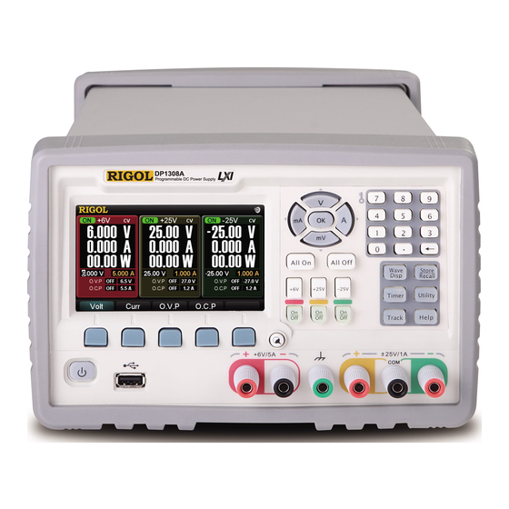
RIGOL DP1308A Overview DP1308A programmable linear DC power supply is designed with high performance and 80W triple-output. Configured with clear user interface, excellent specifications and multiple standard interfaces, DP1308A can fulfill diversified testing demands. Main Features : 4.3 inch, 16M true color TFT LCD;... -
Page 8: Document Overview
List the specifications of DP1308A programmable linear DC power supply. Chapter 2 Quick Start Guide you to quickly understand the using method of DP1308A by introducing the panels, user interface, preparations before use as well as the using method of the rack mount kit. -
Page 9: Table Of Contents
Front/Rear Panel and User Interface ............2-3 Front Panel ..................2-3 Rear Panel ..................2-5 User Interface .................. 2-6 First Use of DP1308A ................2-7 Power Requirement ................2-7 Power-on Inspection ................. 2-7 Output Inspection ................2-8 To Use the Rack Mount Kit ..............2-10 Kit Parts List ................... - Page 10 RIGOL Disassemble/Assemble the Digital Circiut Board ........4-13 Chapter 5 Troubleshooting&Maintenance ..........5-1 Troubleshooting ..................5-1 Maintenance.................... 5-2 System Maintenance ................5-2 Warranty ..................5-3 General Care and Cleaning ..............5-4 DP1308A Service Guide VIII...
-
Page 11: Chapter 1 Specifications
15mV is less than 50μs. Command Processing Time <50ms Temperature Coefficient per ℃ (output percentage + offset) Voltage 0.01%+2mV 0.01%+3mV Current 0.02%+3mA 0.01%+0.5mA Stability ± (output percentage + offset) DP1308A Service Guide... -
Page 12: Power Supply
[2] The maximum time required for regulating corresponding output after receiving the APPLy and SOURce commands. [3] The variation of the output within 8 hours after the instrument is warmed up for 30 minutes and both the load circuit and environment temperatures are constant. DP1308A Service Guide... -
Page 13: Chapter 2 Quick Start
Subjects in this chapter: General Inspection Front/Rear Panel and User Interface Front Panel Rear Panel User Interface First Use of DP1308A Power Requirement Power-on Inspection Output Inspection To Use the Rack Mount Kit Kit Parts List... -
Page 14: General Inspection
RIGOL would not be responsible for free maintenance/rework or replacement of the unit. 2. Inspect the instrument In case of any damage, or defect, or failure, notify your RIGOL sales representative. 3. Check the accessories Please check the accessories according to the packing lists. If the accessories are incomplete or damaged, please contact your RIGOL sales representative. -
Page 15: Front/Rear Panel And User Interface
Programmable DC Power Supply ③ ④ ⑤ ⑥ ⑦ ⑧ ⑨ Figure 2-1 DP1308A Front Panel Display the user interface ① ① Parameter Input Include the numeric keyboard, the unit keys ② Area (direction keys) and the OK key Power Key The instrument enters (or exits) working state ③... - Page 16 This terminal is connected with the chassis and ground wire and is ③ grounded when the instrument is powered on. You can directly connect other electric devices to this terminal to ground them. ④* Ouput terminals of ± 25V channel Remark*: COM is a common terminal. DP1308A Service Guide...
-
Page 17: Rear Panel
Chapter 2 Quick Start RIGOL Rear Panel ① ② ③ ④ ⑤ ⑥ ⑦ ⑧ Figure 2-2 DP1308A Rear Panel GPIB Interface Conform to IEEE 488.2 protocol ① Air outlet of the fan ② Power Hub AC input interface ③ Power Voltage Select the proper scale according to the input ④... -
Page 18: User Interface
(11) (12) (13) (14) (15) (16) (17) (18) (19) (20) (21) (22) (23) (24) Figure 2-3 DP1308A User Interface Channel Output Status (13) Ouput Voltage Channel Label (14) Output Current Current Channel* (15) Output Power Constant Voltage Output (16) O.V.P Input Box... -
Page 19: First Use Of Dp1308A
Power Requirement DP1308A can accept four kinds of AC power supplies (100 V, 115 V, 220 V and 230 V) with 50 Hz to 60 Hz frequency. You can select the desired input power using the “power voltage selector” at the rear panel. -
Page 20: Output Inspection
(3) Inspect the voltage function of +6 V channel. Press +6V and the corresponding On/Off key. The On/Off key is illuminated and the channel is in constant voltage output state. Inspect whether the voltage can be adjusted from 0 to the maximum rated value (6.3 DP1308A Service Guide... -
Page 21: Current Output Inspection
Set the voltage to -25 V. Press the On/Off key corresponding to the -25 V channel. After the On/Off key is illuminated, inspect whether the current can be adjusted from 0 to the maximum rated value (1.05 A). DP1308A Service Guide... -
Page 22: To Use The Rack Mount Kit
Chapter 2 Quick Start RIGOL To Use the Rack Mount Kit DP1308A programmable linear DC power supply can be installed into a standard 19-inch cabinet. Kit Parts List The rack connecting kit consists of the following parts. No. Name Part No. -
Page 23: Installation Space
The machine cabinet must be a standard 19-inch one. At least 4U (177.8 mm) space should be provided by the machine cabinet. The depth inside the machine cabinet should not be less than 460mm. Figure 2-7 Dimensions of the Instrument on the Rack DP1308A Service Guide 2-11... -
Page 24: Installation Tool
The tool below is required for the installation (standard tool as described is recommended). Name Description Phillips Screwdriver PH2 Phillips Screwdriver CAUTION Only authorized personnel can perform the installation operation. Improper operation might damage the instrument or result in incorrect installation of the instrument in the rack. DP1308A Service Guide 2-12... -
Page 25: Installation Procedures
Install the joint parts: align the convexes on the fixing part and interconnector of the instrument with the grooves on both sides of the instrument and insert them into the grooves, then fix them with four M4 countersunk head screws. Figure 2-9 Install the Joint Parts DP1308A Service Guide 2-13... - Page 26 M6 screws, twelve M6 nuts and four M4 screws. The correct hole positions are as pointed out by the black arrows in the figure below. DP1308A Service Guide 2-14...
- Page 27 Figure 2-12 Install the Fixing Accessories on the Cabinet Put into the cabinet: put the fixed instruments into a standard 19-inch cabinet and fix them with four M6 screws, four M6 square nuts and four M4 screws. Figure 2-13 Put into the Cabinet DP1308A Service Guide 2-15...
- Page 28 Chapter 2 Quick Start RIGOL You can also only install one DP1308A into the rack. Install the front guard board: place the front guard board at the position of the other instrument. Fix the front guard board with the instrument using two M4 screws.
-
Page 29: Installation Notice
The rack occupies a height of 4U. The holes pointed out by the arrows are the installation holes and note that they must be aligned with while installing. Figure 2-16 Installation Hole Positions on the Rack DP1308A Service Guide 2-17... -
Page 31: Chapter 3 To Acquire Calibration Service
For any kind of application, a clibration interval longer than 1 year is not recommended. Calibration Notice No matter which calibration interval you choose, RIGOL recommends that you perform overall re-calibration when the calibration interval expires to ensure the accuracy of DP1308A during the next calibration interval. -
Page 33: Chapter 4 Disassemble And Assemble
Phillips screw driver T10, T15 Side cutting plier WARNING Make sure that the power supply is cut off before disassembling the instrument. Only personnel with relative training or relative qualification certification can disassemble the instrument. DP1308A Service Guide... -
Page 34: Outside View Drawing Of The Instrument
RIGOL Outside View Drawing of the Instrument The figure below is the outside view drawing of DP1308A. You need to get a basic understanding of the mian parts of the instrument before disassembling and assembling the instrument. When disassembling or assembling the instrument, please follow the operation steps and take care not to scratch the surfaces of the parts or the PCB board. -
Page 35: Disassemble/Assemble The Front And Rear Rubber Covers
Chapter 4 Disassemble and Assemble RIGOL Disassemble/Assemble Front Rear Rubber Covers Tear the front rubber cover off. Remove the two M4 screws at both sides of the rear panel and take off the rear supporting legs and the rear rubber cover. DP1308A Service Guide... -
Page 36: Disassemble/Assemble The Rear Cover
Chapter 4 Disassemble and Assemble RIGOL Disassemble/Assemble the Rear Cover DP1308A Service Guide... -
Page 37: Disassenble/Assemble The Metal Body
Chapter 4 Disassemble and Assemble RIGOL Disassenble/Assemble the Metal Body DP1308A Service Guide... -
Page 38: Disassemble/Assemble The Up Panel Of The Analog Circuit
Chapter 4 Disassemble and Assemble RIGOL Disassemble/Assemble the Up Panel of the Analog Circuit DP1308A Service Guide... -
Page 39: Disassemble/Assemble The Bottom Panel Of The Analog Circuit
Chapter 4 Disassemble and Assemble RIGOL Disassemble/Assemble the Bottom Panel of the Analog Circuit DP1308A Service Guide... -
Page 40: Disassemble/Assemble The Front Panel
Chapter 4 Disassemble and Assemble RIGOL Disassemble/Assemble the Front Panel DP1308A Service Guide... -
Page 41: Disassemble/Assemble The Keyboard
Chapter 4 Disassemble and Assemble RIGOL Disassemble/Assemble the Keyboard DP1308A Service Guide... -
Page 42: Disassemble/Assemble The Power Frequency Transformer
Chapter 4 Disassemble and Assemble RIGOL Disassemble/Assemble the Power Frequency Transformer DP1308A Service Guide 4-10... -
Page 43: Disassemble/Assemble The Fuse Seat And Fan
Chapter 4 Disassemble and Assemble RIGOL Disassemble/Assemble the Fuse Seat and Fan DP1308A Service Guide 4-11... -
Page 44: Disassemble/Assemble The Gpib Board
Chapter 4 Disassemble and Assemble RIGOL Disassemble/Assemble the GPIB Board DP1308A Service Guide 4-12... -
Page 45: Disassemble/Assemble The Digital Circiut Board
Disassemble/Assemble the Digital Circiut Board It is recommended that you follow the procedures and method introduced above when disassembling and assembling the instrument to avoid damage to the instrument due to improper operation and to save your time. DP1308A Service Guide 4-13... -
Page 47: Chapter 5 Troubleshooting&Maintenance
(3) Pull out the power cord and check whether the voltage selector is at the right scale and whether the fuse is proper and intact. (4) If the problem still remains, please contact RIGOL technical support. 2. Constant voltage output is abnormal: (1) Check whether the maximum output power of the selected channel meets the load requirement. -
Page 48: Maintenance
Besides, regular test and calibration should be performed to ensure the accuracy of the performance. 4. Arrange the instrument properly after you finish the operation of the instrument. 5. Keep the relative accessories of the instrument properly for future use. DP1308A Service Guide... -
Page 49: Warranty
RIGOL warrants that its products mainframe and accessories will be free from defects in materials and workmanship within the warranty period. If a product is proven to be defective within the respective period, RIGOL guarantees the free replacement or repair of products which are approved defective. To get repair service, please contact with your nearest RIGOL sales and service office. -
Page 50: General Care And Cleaning
You can use mild detergent or water. Do not use caustic chemical detergent to avoid damging the instrument. WARNING To avoid injury resulting from short circuit, make sure the instrument is completely dry before reconnecting it to a power source. DP1308A Service Guide...
Need help?
Do you have a question about the DP1308A and is the answer not in the manual?
Questions and answers