Rigol DP1308A User Manual
Programmable linear dc power supply
Hide thumbs
Also See for DP1308A:
- Service manual (50 pages) ,
- Installation manual (13 pages) ,
- Performance verification manual (43 pages)

Related Manuals for Rigol DP1308A


Summary of Contents for Rigol DP1308A
- Page 1 RIGOL User’s Guide DP1308A Programmable Linear DC Power Supply Aug. 2009 RIGOL Technologies, Inc.
-
Page 3: Guaranty And Declaration
Notices RIGOL products are protected by patent law in and outside of P.R.C.. RIGOL Technologies, Inc. reserves the right to modify or change parts of or all the specifications and pricing policies at company’s sole decision. Information in this publication replaces all previously corresponding material. -
Page 4: Safety Notices
Do not Operate in an Explosive connecting. atmosphere. In order to avoid damages to the device Do Not Operate Without Covers. or personal injury, please operate far Do not operate the instrument with away from an explosive atmosphere. User’s Guide for DP1308A... - Page 5 User’s Guide for DP1308A...
-
Page 6: Safety Terms And Symbols
Symbols on the Product. These symbols may appear on the product: Protective Hazardous Refer to Chassis Test Earth Voltage Instructions Ground Ground Terminal User’s Guide for DP1308A... -
Page 7: Dp1308A Overview
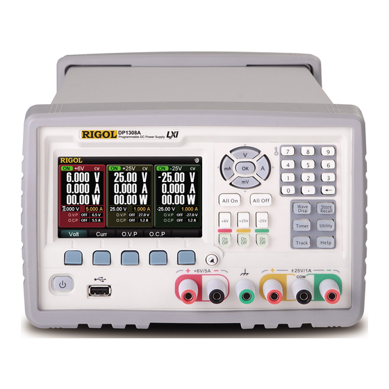
RIGOL DP1308A Overview DP1308A programmable linear DC power supply is designed with high performance and 80W triple-output. It has clear user interface, excellent specifications and multiple standard interfaces, which can meet diversified testing demands. Main Features : 4.3 inch, 16M true color TFT LCD;... -
Page 8: Chapter 4 Troubleshooting
RIGOL Structure of This Document Chapter 1 Quick Start This chapter introduces you the panels and display interface of DP1308A as well as some considerations when first use. Chapter 2 Front Panel Operations This chapter gives detailed information on function and operating methods about each button of the front panel. -
Page 9: Table Of Contents
General Inspection ..................1-2 Front/Rear Panels and User Interface ............1-3 Front Panel ..................1-3 Rear Panel..................1-5 User Interface ..................1-6 First Use DP1308A ..................1-7 Power Requirement ................1-7 Power-On Inspection ................1-7 Output Inspection ................1-8 Display Modes ..................1-11 Chapter 2 Front Panel Operations ............ - Page 10 RIGOL Chapter 6 Appendix ................6-1 Appendix A: DP1308A Accessories .............. 6-1 Appendix B: Warranty ................6-2 Appendix C: General Care and Cleaning ............6-3 Index ......................1 User’s Guide for DP1308A VIII...
-
Page 11: Chapter 1 Quick Start
Chapter 1 Quick Start RIGOL Chapter 1 Quick Start This chapter introduces you the panels and display interface of DP1308A as well as some considerations when first use. From this part, you can learn how to use this instrument quickly and correctly. -
Page 12: General Inspection
Chapter 1 Quick Start RIGOL General Inspection Please inspect your new DP1308A programmable linear DC power supply according to the following steps: 1. Inspect the shipping container for damage. Keep the damaged shipping container or cushioning material until the contents of the shipment have been checked for completeness and the instrument has been checked mechanically and electrically. -
Page 13: Front/Rear Panels And User Interface
Menu softkey With different functions in different menus. ⑤ Display modes Switch display modes between General and Focus ⑥ switching button Channel setting Switch channels, enable/disable channel output ⑦ button Output terminal Channel output connector ⑧ User’s Guide for DP1308A... - Page 14 This terminal is connected with the chassis and ground wire when ③ power on, which could act as an additional ground terminal for the devices connected to. Output terminals of ± 25V channels ④* NOTE*: COM is a public port. User’s Guide for DP1308A...
-
Page 15: Rear Panel
Access LAN via RJ45 port ⑤ Device Connect as a “slave unit” with an external USB ⑥ Port device. Fuse Offer two types of specifications: 250V, T3A and ⑦ 250V, T2A Power Switch Power-on/off the power ⑧ User’s Guide for DP1308A... -
Page 16: User Interface
⑤ ⑥ ⑦ ⑧ ⑨ ⑩ ⑪ ⑫ ⑬ ⑭ ⑮ ⑯ ⑰ ⑱ ⑲ ⑳ Figure 1-3 User interface of DP1308A Channel output state Output voltage ① ⑬ Channel mark Output current ② ⑭ Selected channel* Output power ③ ⑮... -
Page 17: First Use Dp1308A
Power Requirement Four types of AC power within 50Hz-60Hz of frequency are provided by DP1308A: 100V, 115V, 220V, 230V. You can choose an appropriate input power as required through switching the “Power Voltage Selector” on the rear panel. -
Page 18: Output Inspection
Press All Off buttons to disable the output of all channels. Meanwhile, the corresponding On/Off button is black out. User’s Guide for DP1308A... - Page 19 0 to the maximum rated value (5.25A). (4) Inspect the current function of +25V channel. Short the terminal (+) and (COM) of +25V channel using an insulating testing lead; Press +25V button; Set the voltage value as 25V; User’s Guide for DP1308A...
- Page 20 Press -25V button; set the voltage value as -25V; Press the corresponding On/Off button of -25V channel; After On/Off button light goes on, check whether the current can be adjusted from 0 to the maximum rated value (1.05A). User’s Guide for DP1308A 1-10...
-
Page 21: Display Modes
DP1308A provides four display modes: general display mode, focus display mode, general waveform display mode and focus waveform display mode. The output current and voltage can be displayed in waveforms by DP1308A, for the details , please see general waveform display mode (Figure 1-7) and focus waveform display mode (Figure 1-8). - Page 22 Wave Disp button in focus display mode to enter into focus waveform display mode. In this mode, the waveform and channel output state are displayed clearly. Figure 1-8 Focus waveform display mode User’s Guide for DP1308A 1-12...
-
Page 23: Chapter 2 Front Panel Operations
Chapter 2 Front Panel Operations This chapter gives detailed information on function and operating methods about each button on the front panel, among them, you will learn more about DP1308A and make primary work. Following topics are mainly throughout this chapter: Parameter Input ... -
Page 24: Parameter Input
Chapter 2 Front Panel Operations RIGOL Parameter Input DP1308A has two methods to input parameters: dialog box input and direct input (modify). Parameters can be inputted by the digital keyboard and unit key (direction key). Figure 2-1 Digital keyboard and unit key (direction key) - Page 25 While inputting the file name, the position of the cursor can be moved quickly If press direction keys for long time. User’s Guide for DP1308A...
-
Page 26: Constant Voltage Output
RIGOL Constant Voltage Output DP1308A provides two kinds of output mode for each channel including Constant Voltage Output (CV) and Constant Current Output (CC), which is depends on the specified voltage and current as well as the loads carried by the instrument. The instrument will not output voltage or current beyond setting value. - Page 27 Wrong connection may lead damages to the instrument or the equipment connected to. 6. Turn on the output Press the On/Off button below +6V button, and which will be lightened during the output until you press again. User’s Guide for DP1308A...
- Page 28 If channel output is disabled, the O.V.P function can not be enabled but only for inputting value. If the output voltage beyond the value of overvoltage protection, the output will be disabled automatically. *: Please use O.V.P function as required. User’s Guide for DP1308A...
- Page 29 If channel output is disabled, the O.C.P function can not be enabled but only for inputting value. If the output current beyond the value of over current protection, the output will be disabled automatically. *: Please use O.C.P function as required. User’s Guide for DP1308A...
-
Page 30: Constant Current Output
Press +6V to enable +6V channel, at present, the channel is highlighted on the screen (in breath state). 3. Set the voltage Press Volt and set the voltage to 6 V. Figure 2-7 Set the voltage 4. Set the current Press Curr and set the current to 5 A. User’s Guide for DP1308A... - Page 31 Wrong connection may lead damages to the instrument or the equipment connected to. 6. Turn on the output Press the On/Off button below +6V button and which will be lightened during the output until you press again. User’s Guide for DP1308A...
- Page 32 If channel output is disabled, the O.V.P function can not be enabled but only for inputting value. If the output voltage beyond the value of overvoltage protection, the output will be disabled automatically. *: Please use O.V.P function as required. User’s Guide for DP1308A 2-10...
- Page 33 If channel output is disabled, the O.C.P function cannot be enabled but only for inputting value. If the output current beyond the value of overcurrent protection, the output will be disabled automatically. *: Please use O.C.P function as required. User’s Guide for DP1308A 2-11...
-
Page 34: Timing Output
“Next” denotes the next output voltage and current setting value. The next output value does not displayed in normal display mode, see the figure below. Figure 2-13 Timing output (normal display mode) User’s Guide for DP1308A 2-12... - Page 35 If the timing output is enabled on a channel, of which Volt and Curr values can’t be set. Timing Output can not be used if tracking function of +25V (-25V) channel is active. User’s Guide for DP1308A 2-13...
-
Page 36: Multiplexed Output
Chapter 2 Front Panel Operations RIGOL Multiplexed Output Typically, all three channels of DP1308A enable to output synchronously, and each of them could be controlled independently. Operation Steps: 1. Power on Press to start-up the instrument. 2. Choose and set channels Press the channel selection button to choose the channel required to output, then separately set the voltage and current for each of them. - Page 37 Chapter 2 Front Panel Operations RIGOL 6. How to output 0V~50V power* DP1308A can output 0V~50V power by connecting +25V channel in series with -25V channel, see the figure below. -25V +25V Figure 2-15 Connect +25V and -25V channel in series...
-
Page 38: Tracking Output
For example: Change the voltage of -25V channel to 2.5V, the voltage of +25V channel is also changed to 2.5V, please see the figure below. Figure 2-17 Tracking output (after tracking) Press Track again to disable track function and the light is out. User’s Guide for DP1308A 2-16... - Page 39 CV state. Track function is forbidden when “Timing Output” of +25V (-25V) channel is active. The voltage of channel under tracking can not be set manually when track function is enabled. User’s Guide for DP1308A 2-17...
-
Page 40: Save And Recall
Chapter 2 Front Panel Operations RIGOL Save and Recall DP1308A supports two types of document storage ways: U disc storage and local storage. Among the internal memory, 4 groups of settings could be saved or recalled and more settings are available for USB device. - Page 41 “北京普源” in the same way. (2) Delete the wrong characters you input In the process of editing, if press “←”, the characters in display box will be deleted at first. User’s Guide for DP1308A 2-19...
- Page 42 Press Save to save the file as the specified name and finish editing. NOTE The length of Chinese file name must be less than 6 characters and the English name must be less than 12 letters (including number). User’s Guide for DP1308A 2-20...
-
Page 43: Set Up The Utility
Explanation Set the LAN parameters and GPIB address and view the ID of USB device Set system parameters Calibrate Enter the calibration interface TimerSet Set the timing parameters for each channel Exit Exit utility menu User’s Guide for DP1308A 2-21... -
Page 44: I/O Setting
Chapter 2 Front Panel Operations RIGOL I/O Setting DP1308A provides LAN, USB and GPIB three interfaces for communication; you can set and review the related parameters through setting interface. Press I/O → LAN, enter the following interface. Net Connection: Link/Unlink... - Page 45 1~30. See the figure below, directly input the desired address by number keyboard and then press OK to save. Press “←” or the left direction key to delete the number before the cursor. Figure 2-25 Set the GPIB address User’s Guide for DP1308A 2-23...
-
Page 46: System Setting
instrument. Brightness Setting Press Bright to enter the brightness setting interface. The brightness of display screen could be regulated by pressing “+”/ “-” key (in menu) or left/right direction key. Figure 2-27 Brightness setting User’s Guide for DP1308A 2-24... - Page 47 Press Beeper to enter into setting interface. A sign would shown at Status Bar once you turn on beeper, which indicates that the instrument may buzzed once pop up a hint message or some button is pressed down. Figure 2-29 Beeper settings User’s Guide for DP1308A 2-25...
-
Page 48: View System Information
Figure 2-30 Self-Test menu Figure 2-31 View Self-Test Result View System Information Press Sysinfo to view the Model, Serial Number, Hardware Version, Logic Version and Software Version of the instrument. Figure 2-32 System information settings User’s Guide for DP1308A 2-26... -
Page 49: Calibrate
Before enter the calibration interface, correct password must be input. Figure 2-33 Input interface of calibration code NOTE The instrument has been calibrated before leaving factory. Personal calibration is not recommended. For calibration help, please contact RIGOL technical support. User’s Guide for DP1308A 2-27... -
Page 50: Timer Setting
“Left(s)” is on the decrease until to 0, at this moment, the instrument enters next group and so on until finish outputs of all settings. User’s Guide for DP1308A 2-28... -
Page 51: Online Help System
After you press Help (the light is on), a letter “HELP” will shown at status bar; then, press desired help button and the related help information will shown on the screen, meanwhile, Help light goes out and the letter “HELP” disappears. Press Exit to quit help menu. Figure 2-35 Help information User’s Guide for DP1308A 2-29... -
Page 52: Key Lock
To unlock the keyboard, press “Little Key” again. Remote Mode In Remote mode, all buttons are locked automatically except power button “Little Key” and All Off. To exit remote mode, press “Little Key” again. User’s Guide for DP1308A 2-30... -
Page 53: Chapter 3 Remote Control
Please take the following steps to operate: 1. LAN Setting Make sure DP1308A has been connected to local area network, then press I/O → LAN to enter LAN parameter setting interface. Set and obtain IP address referring to the introduction of “I/O Setting”... - Page 54 (4) Click “Web Control” icon to get the following interface, you could change the instrument setting by using the mouse to click corresponding keys* via virtual panel, so as to achieve remote control of DP1308A. User’s Guide for DP1308A...
- Page 55 NOTE*: Several keys or functions cannot be controlled via network, to which an icon “○ ” will appear when the mouse is pointing. Figure 3-5 Control DP1308A via web Explanations: In condition of instrument password is effective, the system will pop up a dialog as figure below when use “Network Settings”...
- Page 56 “Network Settings” and “Web control” has been modified successfully. Figure 3-8 Security interface (7) Click “LXI” icon to enter LXI website (http://www.lxistandard.org/), so as to obtain more information about LXI standard. User’s Guide for DP1308A...
-
Page 57: Chapter 4 Troubleshooting
(3) Pull out the power cord from instrument and ensure the voltage selector is in right scale and the fuse is suitable and intact. (4) If the problem still remains, please ask RIGOL for help. Constant voltage output is abnormal: (1) Check whether the maximum power from selected channel meets load requirement. -
Page 59: Chapter 5 Specifications
Chapter 5 Specifications RIGOL Chapter 5 Specifications DP1308A Programmable Linear DC Power Supply specification and operating characteristics are based on the instrument having been operated continuously for 30 minutes under the specified operating temperature. NOTE: All the specifications below apply to all the three channels output unless where noted. - Page 60 [1] Specifications are for one hour warm-up and at 25 [2] The maximum time required for regulating corresponding output when received APPLy and SOURce commands. [3] The variation of output within 8 hours after warm-up 30 minutes and both the load circuit and User’s Guide for DP1308A...
- Page 61 Chapter 3 Specifications RIGOL environment temperature are in constant conditions. User’s Guide for DP1308A...
-
Page 63: Chapter 6 Appendix
An USB data cable A CD (including User’s Guide) An INSTRUCTION Four fuses (two of 250V/T3A and two of 250V/T2A) NOTE: All the accessories are available by contacting your local RIGOL office. User’s Guide for DP1308A... -
Page 64: Appendix B: Warranty
To get repair service or obtain a copy of the whole warranty statement, please contact with your nearest RIGOL sales and service office. RIGOL does not provide any other warranty items except the one being provided by this summary and the warranty statement. The warranty items include but not being subjected to the hint guarantee items related to tradable characteristic and any particular purpose. -
Page 65: Appendix C: General Care And Cleaning
When clean the LCD, take care to avoid scarifying it. WARNING To avoid injury resulting from short circuit, make sure the instrument is completely dry before reconnecting into a power source. User’s Guide for DP1308A... -
Page 67: Index
LAN .......... 2-22 Timing ....2-1, 2-2, 2-12, 2-28 Language ........2-24 Transient Response Time ....4-1 Linear Regulation ......4-1 USB ........... 2-23 Load Regulation ......4-1 Voltage Programming Speed ..4-2 Local Mode ........ 2-30 User’s Guide for DP1308A...
Need help?
Do you have a question about the DP1308A and is the answer not in the manual?
Questions and answers