
Related Manuals for Alto ? MICtube


Summary of Contents for Alto ? MICtube
- Page 1 User's Manual MICtube STEREO TUBE PREAMP www.altoproaudio.com Version 1.0 April 2002 English...
- Page 2 SAFETY RELATED SYMBOLS External Connection CAUTION The external wiring connected to the RISK OF ELECTRIC SHOCK DO NOT OPEN output hazardous live terminals requires installation by an instructed person, or the This symbol, wherever it appears, alerts you to the presence of use of ready-made leads or cords.
- Page 3 the apparatus body. Install in accordance with the manufacturer's Clean only with dry cloth. instructions. Do not install near any heat sources such as radiators, heat registers, Servicing: stoves, or other apparatus (including am- Refer all servicing to qualified personnel. plifiers) that produce heat.
- Page 4 the apparatus body. Install in accordance with the manufacturer's Clean only with dry cloth. instructions. Do not install near any heat sources such as radiators, heat registers, Servicing: stoves, or other apparatus (including am- Refer all servicing to qualified personnel. plifiers) that produce heat.
- Page 5 Preface Dear Customer, Thanks for choosing LTO Stereo Tube Preamplifier and thanks for choosing of the results of LTO AUDIO TEAM job and researches. For our LTO AUDIO TEAM, music and sound are more than a job...are first of all passion and let us say ..our obsession! We have been designing professional audio products for a long time in cooperation with some of the major brands in the world in the audio field.
-
Page 6: Table Of Contents
TABLE OF CONTENT 1. INTRODUCTION ................5 2. FEATURE LIST ................5 3. CONTROL ELEMENTS ..............5 3.1 The Front Panel a. Guidepost of The Front Panel b. Supplementary Descriptions 3.2 The Rear Panel a. Power Supply Connection b. Analogue Inputs/ Outputs 4. INSTALLATION & CONNECTION...........8 4.1 Mains Connection 4.2 Audio Connection a. -
Page 7: Introduction
1. INTRODUCTION Thank you very much for expressing your confidence in LTO products by purchasing our MICtube Stereo Tube Preamplifier. With the MICtube you have acquired an extremely musical and flexible Stereo Microphone Preamplifier which is based on many years of experience and findings in amplifier technology and is used through the world in renowned studios, sound reinforcement systems as well as in broadcast and television studios. -
Page 8: Guidepost Of The Front Panel
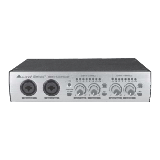
a. Guidepost of the front panel Power LED CHANNEL 1 Output Level Display LED CHANNEL 2 Output Level Display LED Phantom Power Switch (5)(6) Phase Reverse Switch (7)(8) 20dB PAD (9)(10) Combination Microphone (XLR) and Instrument (1/4 inch) input (11)(13) Input Gain Control (0 to 30 dB) (12)(14) Drive Control (0 to 40 dB) b. -
Page 9: The Rear Panel
( -10dbV ) or professional level ( +4dbu ) . when the gain is too low, the tube effect becomes less audible and the S/N (Signal to Noise) ratio deteriorates. Generally, Dynamic mics and instruments without preamps will require more gain than condenser mics and instruments that have a built-in preamp. -
Page 10: Installation & Connection
4. INSTALLATION & CONNECTION : 4.1 Mains Connection - Please ensure that the MICtube Stereo Microphone Preamplifier is connected to the correct supply voltage before operating this unit. - Only use the 18VAC AC/AC Adaptor provided by LTO. 4.2 Audio onnection MICtube Stereo Tube Preamp presents with balanced XLR... -
Page 11: Rack Mounting
Balanced Ring Ring Sleeve Sleeve TIP RING SLEEVE SLEEVE RING TIP Ring Sleeve TIP RING SLEEVE Unbalanced Ring Sleeve TIP RING SLEEVE Sleeve TIP SLEEVE Centre Screen Sleeve Sleeve TIP SLEEVE SLEEVE TIP Ring Ring Sleeve Sleeve TIP RING SLEEVE SLEEVE RING TIP Centre Sleeve... -
Page 12: The Mictube As A Direct-Injection Ox (Di Box) B
produce extreme levels on the output side, which may damage subsequent devices, so you should turn down all the level controls beforehand, or you can press the 20dB Pad (7/8) to attenuate the incoming signal level about 20dB, then hook up a microphone to the XLR and 1/4" Combination Input ( 9 / 10 ), use either the jack or XLR output connectors to connect the audio system. -
Page 13: Technical Specifications
6. TECHNICAL SPECIFICATIONS 6.1 Block Diagram... -
Page 14: Specifications
6.2 Specifications Input XLR Impedance 5K Ohm 1/4" High Z 1M Ohm Connectors Neutrik Combo Output XLR Balanced 100 Ohms 1/4" Unbalanced 100 Ohms Panel Controls Tube Drive 0dB to +40dB Gain 0dB to +30dB Phase Reverse 20dB Pad +48V Phantom Power Performance THD + Noise <0.5%... -
Page 15: Warranty
7. WARRANTY 1. WARRANTY REGISTRATION CARD To obtain Warranty Service, the buyer should first fill out and return the enclosed Warranty Registration Card within 10 days of the Purchase Date. All the information presented in this Warranty Registration Card gives the manu- facturer a better understanding of the sales status, so as to purport a more effective and efficient after-sales warranty service.
Need help?
Do you have a question about the ? MICtube and is the answer not in the manual?
Questions and answers