
Related Manuals for Datavideo HS-500


Summary of Contents for Datavideo HS-500
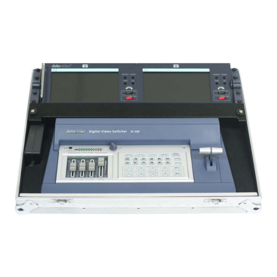
- Page 1 Digital Video Switcher HS-500 Error! INSTRUCTION MANUAL Http://www.datavideo-tek.com Rev 121006...
-
Page 2: Table Of Contents
Radio and Television Interference Warranty Disposal Introduction Introduction Product overview Features Packing List HS-500 General Operation Some General Notes on Installation Setting Up Connecting Video Sources and Power Cable SE-500 Front panel Rear panel Selecting video input formats and adjusting audio levels... - Page 3 SE-500 Troubleshooting / FAQ No power No image at output / S-Video output is black and white Audio clipping Frozen image at output Image distortions etc How does RS 232 work in practice SE-500 Appendix RS-232 Remote Control Commands MIDI Control Commands Tally Pinouts cross reference between the TLM-404 &...
-
Page 4: Warnings And Precautions
7. This product should only be operated from the type of power source indicated on the marking label of the AC adapter. If you are not sure of the type of power available, consult your Datavideo dealer or your local power company. -
Page 5: Warranty
Equipment that fails after the warranty period, has been operated or installed in a manner other than that specified by Datavideo, or has been subjected to abuse or modification, will be repaired for time and material charges at the Buyer’s expense. This warranty does not affect your statutory rights within the Country of purchase. -
Page 6: Features
Self contained in metal transit case for rapid set up / breakdown Compact and lightweight one box solution Packing List 1. HS-500 Mobile Video Studio x 1 2. BNC to BNC 1.2m cable x 2 3. S-Video 1.2m Cable x 1 4. -
Page 7: Hs-500 General Operation
Unlock the two locks and lift the lid. The hinges at the back of the HS-500 have been designed so that once the lid is at an angle of 45 - 90 degrees it can be slid to the left and removed. -
Page 8: Connecting Video Sources And Power Cable
Connecting Video Sources and Power Cable Firstly remove the cover by unscrewing the two thumb screws, this allows easier access to the rear of the SE-500 With the cover removed you can see the rear panel of the SE-500 At the rear of the case there is a cable flap, unlock it so that it hinges down to allow access. - Page 9 Thread the power cable through the cable access flap and insert it into the PSU. Now connect your video and audio inputs and outputs from your cameras etc. For more details see the SE- 500 section of this manual. With everything connected switch the SE -500 on and then replace the cover.
- Page 10 Note: The HS-500 connections use the V1 inputs on both monitors. Make sure that the source switches are both set to V1. Note: When packing away the HS-500 please ensure that the monitors are folded flat before replacing the lid on the transit case.
-
Page 11: Se-500
SE-500 SE-500 Front Panel 1. Audio faders 9. Background color selection/Menu 2. Headphone Socket 10. Border On/Off 3. Audio meters 11. T-Bar 4. Headphone Volume Control 12. Transition Effect preview 5. Video Effect: Quad 13. Main Video Source selectors 6. Video Effect: Split 14. - Page 12 1. Faders: sliders to control audio levels for the Main audio output mix. These Audio Level pots are the first stage in the audio signal path. Analog audio comes in through the 1/4 inch phono jack and RCA connectors on the rear panel see Rear Panel, page 14.
- Page 13 9. Background: When Background is selected in either the Main or Sub Video Source (13, 14.), and the button is pressed (and the LED is lit except with black color background), repeated presses of the color button cycle through the 8 possible solid backgrounds. For more information, see Background, page 29.
- Page 14 16. Transition selectors: These twelve selection buttons determine the transition type and allow for the selection of certain effects that are performed on the selected Main Video Input channel. For more information, see Using Transitions, page 24 and Using Effects, page 27. Tech note : Transcoding is the act of changing video from one format to another, for example, from composite video to S-video.
-
Page 15: Se-500 Rear Panel
SE-500 Rear Panel 2c 2b 10. Video inputs, Channels 1, 2, 3, 4. 1. RS-232 Control 1a. S-Video (Y/C) input 2. Tally Signal out 1b. Composite video input (BNC) 3. MIDI Control* 11. Video outputs 4. Microphone input Ch2 (1/4” jack) 2a. - Page 16 1. Video In (Channels 1, 2, 3, and 4 are all set up the same way) a. Composite video input: takes a BNC connector from the composite output of a VCR, camera, DVD player, etc. b. S-Video (Y/C) input: takes a standard 4 pin S-video cable from the output of a VCR, camera, DVD player, etc.
- Page 17 8. Audio Inputs: A RCA stereo for a line level auxiliary analog audio source, such as a CD player or tape deck. If you are using more than two sources via an external audio mixer, connect the audio mixer’s line level output to this unbalanced Audio input.
-
Page 18: Selecting Video Input Formats And Adjusting Audio Levels
Selecting video input formats and adjusting audio levels (Numbers refer to the Front Panel illustration above)*. Verify that there is a valid source at each input you’ve connected by using the Main Source Select buttons (13.) to select a channel and view the output on the main monitor. For each input channel (1, 2, 3, 4): connect either a Composite or S-Video source to each channel. -
Page 19: Dissolving Between Sources
Dissolving between sources Select the Main Video Source (13.) by pressing the appropriate channel button. The LED for the channel you have selected should be lit and you should see that source on the program monitor. Select the Sub Video Source (14.) you want to dissolve to. The default transition is fade (The LED should be lit when you turn on the switcher. - Page 20 PIP effect (7.), which stands for Picture in Picture. As you might guess, this effect requires a Main and Sub Video Source. Assuming you have valid inputs on Channel 1 and 2, select Channel 1 as the Main Source and Channel 2 as the Sub Source. When you engage the effect by pressing the PIP button (and verifying that the LED on the button is lit), on the program monitor you will have Channel 1 as the Main Source and Channel 2 as a smaller window inset.
-
Page 21: Controls And Operations
Controls and Operations Video Source The first thing to do when using the SE-500 is to select the Main and Sub Video Sources. The source you select (by pressing one of the buttons; a bright red LED on the selected button lights for confirmation) on the Main Source bus is what is sent to the Video output. -
Page 22: Color Processor
Color Processor The Color Processor controls work when you press and hold the “Background” (9.) button for 2 seconds or more, which is temporarily displayed at the Preview Output. For more information, please see the “MENU” section. These controls are like picture controls on a video monitor or the proc amp (processing amplifier) controls on a time base corrector. -
Page 23: Menu
The most serious, accurate color correction is done with the aid of a waveform monitor/vector scope, a signal analysis instrument (actually a pair of instruments) common in video editing suites, which shows precisely the details of the video signal. With one of these instruments, you can see at a glance (once you know what you are looking for) the most intimate electronic details and irregularities of the video signal. -
Page 24: Audio Inputs, Levels, And Meters
Audio Inputs, Levels, and Meters (Faders, bus selectors,) Audio Input Level Calibration Procedure The first step in setting up the audio for a session with your SE-500 consists of adjusting the levels on which channel you will be using. Slide the Master fader to Max, and set the other faders to 0. Then, listening to the audio and watching the Audio Level Meters (see below), set the level with the fader so that the sound is consistently at between +0 dB (green LED) and +8 dB (yellow LED) and just barely peaks occasionally to +10 dB (red LED). -
Page 25: Using Transitions
Using Transitions The SE-500 can do 3 kinds of transitions: cut, fade, and wipe. The cut is a simple switch from one input source to another, and can be accomplished by selecting a source on the Main Source Bus, and then selecting a second one. -
Page 26: List Of Transitions
List of transitions and parameters (suitable for photocopying) Wipe (works in conjunction with Border controls): Block wipe from center to full screen. Right angle wipe on, upper right to lower left Right angle reveal, lower right to upper left Right angle wipe on, upper left to lower right Right angle reveal, lower left to upper right Horizontal wipe, top to bottom Horizontal wipe, bottom to top... - Page 27 Vertical wipe, middle to left and right Horizontal wipe, middle to top and bottom...
-
Page 28: Using Effects
Using Effects The SE-500 is capable of producing a wide variety of digital effects. These falls into 2 categories: single channel and dual channel effects. Single channel effects are produced on the source selected in the Main Video Source bus and need no second video input. -
Page 29: Effects: Quad
Effects: Quad The Quad effect combines 4 input videos into 1 output. When this effect is activated, it shows 4 video sources on 1 single monitor. Each source takes one quarter of the entire screen. Press the button again, and it returns to the previous selected source in full screen. -
Page 30: Border
Border These controls are used in conjunction with the Picture in Picture Effect and Wipe transition only, and can only be activated when the Picture in Picture or Wipe control is active. 8 Colors are available for the wipe border: black, blue, magenta, red, green, cyan, yellow and white. See “Background Color”... -
Page 31: Four Camera Shoot: Live Stage Performance/Sporting Event
The four cameras are feeding analogue signals to the SE 500, via Composite or S-Video. It would be possible to use DV cameras by adding a Datavideo DAC 6 to each of the channels that you want to run DV. -
Page 32: Live Conference
Live Conference In this second example we see a typical conference set up. There are two cameras to handle the speaker and the overview, with audience reaction or other action on the stage. Both cameras are analogue, but by adding a DAC 6 to any of the channels it would be possible to use a DV camera. -
Page 33: Live Event Mixing: Club Vj/Concert
Live Event Mixing: Club VJ / Concert In our final example we are looking at a typical V.J. set up. Increasingly in clubs video images are used to add to the overall effect and atmosphere, they are combined with light displays and other audio / visual effects. -
Page 34: Using Se-500 With Cg-100 For Titles/Graphics/Logos Overlay
Using SE-500 with CG-100 for Titles/Graphics/Logos overlay Using YUV output (with a breakout cable) on SE-500 to communicate with a PC with Decklink SP CG overlay card and CG-100 CG software (page 42) to perform a text overlay for the output video. -
Page 35: No Power
Troubleshooting / FAQ No power No image at output / black and white output from S-Video (Y/C) Audio clipping Audio or video feedback Frozen image at output Image distortions How does the RS 232 work in practice No power Check that the power supply is plugged into the SE 500, and to a suitable mains outlet, and that it is switched on. -
Page 36: Rs-232 Remote Control Commands
SE500 RS-232 Remote Control Command VER: 1.01 Release date: 2006/01/19 1. Physical layer Control output format: RS-232C Communication rate: 57600 BPS Data format: 8 bits serial, LSB first, 1 start bit, 1 stop bit, odd parity Must delay 100uSEC between 2 bytes 2. - Page 37 1) The command group 05h (base 16) = SE500 control command 2) The operated refer to section 4. 3.2 Return data format 10th 11th … Command parameter parameter parameter parameter parameter parameter parameter … Status 1) The command status 05h=SE500 control command status 2) The parameter refers to section 6.
- Page 38 15h= key_left_bottom_block (wipe) 16h= key_top_block (wipe) 17h= key_bottom_block (wipe) 18h= key_right_block (wipe) 19h= key_left_block (wipe) 1ah= key_horizontal (wipe) 1bh= key_vertical (wipe) 20h= key_border_on 22h= key_background_color 24h= key_speed* 26h = key_PIP 3bh = key_menu 3ch = key_up 3dh = key_down 3eh = key_left 3fh = key_right 40h = key_reset 41h = key_plus...
- Page 39 4) The effect No. The value from 0 to 99(63h) Fade effect No. = 0 Wipe effect No.= 0 to 10 Quad effect No.= 0 POP effect No. = 0 to 1 PIP effect No.:bit3 to bit0= x0h to x4h (position) Bit4=0=big size, bit4=1=small size Bit5=0=not shift, bit5=1=shift to close center.
- Page 40 7. EXAMPLE 1) PC control SE500, key command = key_take= 0fh a.) The command stream = F0h,32h,0eh,05h,01h,0fh,,30h,34h,ffh Header=F0h ID=32h Length = 9 bytes=09h Command group=05h Command mode=normal control code=01h Control key code=key_take =0fh checksum= (f0h+32h+09h+05h+01h+0fh) = 40h checksum_low =00h+30h = 30h checksum_high=04h+30h = 34h END =ffh b.) SE500 return data,...
- Page 41 SE500 MIDI Remote Control Command VER: 1.00a Release date: 2005/06/03 1. Physical layer Follow the MIDI SPEC. 1.0 Communication rate: 31250 BPS Data format: 8 bits serial, LSB first, 1 start bit, 1 stop bit, none parity 2. Data link layer 2.1 Control messages = MIDI Channel voice messages * Received only if Note Mode is ON * The input of each channel is selected.
- Page 42 SUB D key PIP key SUB BG key Freeze key Preview key TAKE key MAIN A key Background color key MAIN B key Border key MAIN C key MAIN D key Speed _1 key MAIN BG key Speed_ 2 key Change Speed key Speed_ 3 key 4.
- Page 43 SE500 Tally Pin Outs Cross Reference VER: 1.00 Release date: 2005/07/07 LED A3 = pin 1 = 1R (Main1) LED A2 = pin 2 = 1G LED A1 = pin 3 = 1Y (Sub1) Green Ground = pin 4 = GND Video Red LED Yellow LED...
-
Page 44: Specifications
Specifications Video Formats Analog Y/C, Composite CCIR601 NTSC and PAL (PAL and NTSC are separate models) Video Inputs 4 – S (Y/C), Composite Video Output 1 – Quad Video source monitoring (Composite) 2 – Composite 1 – S (Y/C) 1 – Component (With breakout cable, it uses the S (Y/C), and one Composite output.) Audio Inputs 1 –... -
Page 45: Tlm-702
Functions - Front Panel Each monitor has a two color tally light indicator which can be connected to the Datavideo RMC 140, SE500 or similar products. AMBER indicates Cued and RED indicates Live. Each Monitor has individual adjustments for Brightness, Contrast, Color and Tint (Tint is for NTSC only). -
Page 46: Rear Panel
TLM-702 from other regulated 12V supplies (min 1.5A). 3.5mm Jack Socket for tally light connection. You can connect the tally feed from the Datavideo SE 500, RMC-140, RMC90 or other similar equipment. Each monitor has two composite video inputs, each with a loop-through output. The video input can be PAL or NTSC, the TLM-702 will automatically detect the video standard. -
Page 47: Specifications
Specifications LCD Display 7" x 2 TFT LCD active matrix, resolution 1440 x 234 dots Aspect Ratio 4:3 and 16:9 selectable Brightness (Luminance) 500 cd/m² Contrast Ratio View Angle Top: 40 deg Bottom: 60 deg Left: 60 deg Right: 60 deg Video Input CV input 1.0Vp-p, with self Loop-Through output (75 Ohm-terminated) -
Page 48: Useful Accessories
Thanks to Blackmagic Design and Datavideo the solution is at hand. Blackmagic Design have introduced a low cost range of SDI solutions, which are called the “Decklink Series”, and Datavideo have developed the first software for displaying VGA directly out thru these Decklink... - Page 49 SDI cards. The Datavideo PPT-100 takes full advantage of the Decklink card and Intel 915 chipset technology. Users can easily convert PC images (VGA) to SDI, change image position and size, and select different colors for the pointer; and then, display on projector or large TV wall. With a vision mixer / switcher such as the SE-800, you can also combine DVD player, DV camera, VCR, VHS and CD player for a perfect presentation.
- Page 50 20 meters for cable runs of up to 200 meters One channel DV repeater (VP-314) 20/10 meter DV cable P/N: 2066/1066 One input to five channels output DV-DA (VP-332) Please check website (www.datavideo.info) for the most up to date list, descriptions, and pricing of accessories for the HS-500.
-
Page 51: Service And Support
It is our goal to make your products ownership a satisfying experience. Our supporting staff is available to assist you in setting up and operating your system. Please refer to our web site www.datavideo-tek.com for answers to common questions, support requests or contact your local office below.
Need help?
Do you have a question about the HS-500 and is the answer not in the manual?
Questions and answers