Table of Contents
Advertisement
Quick Links
Advertisement
Table of Contents

Related Manuals for Datavideo VSM-100


Summary of Contents for Datavideo VSM-100
-
Page 1: Quick Start Guide
VECTOR SCOPE MONITOR VSM-100 Quick Start Guide www.datavideo-tek.com... -
Page 2: Table Of Contents
What’s in the box? ........................4 Connections & Control ....................... 5 Menu Options (Monitor) ......................10 VSM-100 Output Display ......................12 Menu Control and Options ....................... 13 VSM-100 Quick Start Guide ..................... 16 Dimension ..........................23 Specification ..........................24 Service & Support ........................25... -
Page 3: Warnings And Precautions
7. This product should only be operated from the type of power source indicated on the marking label of the AC adapter. If you are not sure of the type of power available, consult your Datavideo dealer or your local power company. -
Page 4: Warranty
Certain parts with limited lifetime expectancy such as LCD Panels, DVD Drives, Hard Drives are only covered for the first 10,000 hours, or 1 year (whichever comes first). Any second year warranty claims must be made to your local Datavideo office or one of its authorized distributors before the extended warranty expires. -
Page 5: Introduction
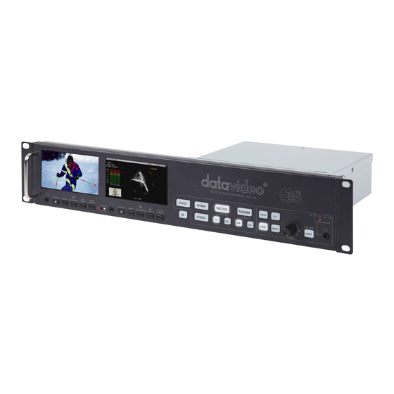
Introduction This newly created VSM series from Datavideo, the VSM-100 is a sophisticated system that allow users to easily ensure the stability of incoming video signals and recorded video quality from connected recorder and cameras thru two 4.3” monitors to display and monitor high quality images. By equipped with sampling vector scope- the VS-150, at the rear, it can accurately assist camera calibration, ensure precise Black/White Balance calibration, supports color saturation, and enable luminance adjustment. -
Page 6: Connections & Control
Connections & Control Front Panel Monitor Area Vector Scope Area Monitor Area Power Switch Switches the monitor power On / Off. Stereo mini jack plug (Monitor) For stereo headphones. The headphone volume is controlled by the Audio Level button. N.B. Audio source from HDMI or SDI audio embedded audio. Source Button Select Input source between HD-SDI / SDI and HDMI. - Page 7 Switches the power On / Off. HISTOGRAM HISTOGRAM is used to detect the overall brightness of a location. Through VSM-100 to detect light sources from all directions reading by the camera, one can individually adjust each camera to the desired state.
- Page 8 TRACE MEMORY This mode is allowed you save trace, recall trace or clear trace. To recall the saved camera signals, the camera signals are consistent when camera signals (displaying in various colors) are overlapping with the one another. MENU Menu dial and push to select button Turn the knob to select the options or adjust the parameter.
-
Page 9: Rear Panel
REMOTE: Switch to REMOTE for control VSM-100 mode. LOCAL: For firmware update mode; if you want upgrade VSM-100 firmware please switch to LOCAL and via USB cable connect to PC for firmware update. Mini USB USB interface for firmware update HD/SD-SDI INPUT BNC connector for SDI input. - Page 10 Monitor Area HD/SD - SDI input BNC connector for SDI Input. HD/SD - SDI loop through output BNC connector for HD / SD SDI with a loop through output. HDMI in interface HDMI digital signal input connecter. Support HDMI 1.1 DC in socket Connect the supplied 12V PSU to this socket.
-
Page 11: Menu Options (Monitor)
Menu Options (Monitor) Picture - Press the MENU button into the system Picture setting mode. - Press ENTER button into the Picture setting position. - Press UP / DOWN button moving to the Brightness setting. - Press ENTER button into the Brightness setting position. - Press UP / DOWN button to setting the Brightness values from 0~100 - Press MENU button return to the Picture setting menu. - Page 12 Setup - Press the MENU button four times into the Setup setting mode. - Press ENTER button into the Setup setting position. - Press UP / DOWN button moving to the OSD Timer setting. - Press ENTER button into the OSD Timer setting position. - Press UP / DOWN button to select the OSD display on screen time (value from 5~60 SEC).
-
Page 13: Vsm-100 Output Display
VSM-100 Output Display... -
Page 14: Menu Control And Options
Menu Control and Options The VSM-100 is a menu driven unit. The menu is viewed as part of the output display when it has been connected to a HDMI / SDI monitor The menu options are scrolled by turning the Menu Dial to the left or right (See item 1 on page 8). A pointer ( ►) to the left of the menu options indicates which item is currently selected. - Page 15 TRACE MEMORY This option allows the current VSM-100 scope trace to be saved, recalled or cleared within the unit’s memory. A saved or recalled trace will be displayed in green sample points and the live or current signals will be displayed in white sample points.
- Page 16 Audio embedded into the SDI / HD-SDI signal can be monitored by plugging headphones into the 3.5mm jack socket on the VSM-100 front panel. Using the AUDIO VOLUME option, the Menu Dial can be used to increase or reduce the volume at the connected headphones, so it is monitored at a comfortable level.
-
Page 17: Vsm-100 Quick Start Guide
2. Turn on any set lights and ensure any coloured filters are removed. We want an evenly lit white reference card or background with only true white light. 3. Select VECTORSCOPE mode on the VSM-100 using the NEXT MODE option. 4. Use the camera’s auto white balance feature to white balance against the solid white background or reference white card. - Page 18 6. Once the first camera is correctly calibrated select TOOLS> TRACE MEMORY> SAVE TRACE to save the calibrated matrix levels from the first camera. 7. Now connect VSM-100 to the second camera on the set. Adjust the white and black balance on the next camera as described earlier.
- Page 19 5. Once the first camera is correctly calibrated select TOOLS> TRACE MEMORY> SAVE TRACE to save the calibrated matrix levels from the first camera. 6. Now connect VSM-100 to the second camera on the set. Adjust the white and black balance on the next camera as described earlier.
- Page 20 5. Once the first camera is correctly set for colour select TOOLS> TRACE MEMORY> SAVE TRACE to save the current parade trace from the first camera. 6. Now connect VSM-100 to the second camera on the set. Adjust the white, black balance and luminance on the next camera as described earlier.
- Page 21 1. Under the same on set lighting conditions aim the camera at a colour reference chart (such as DSC labs’ Chroma Du Monde). 2. Select VECTORSCOPE mode on the VSM-100 using the NEXT MODE option. 3. Now, the VECTORSCOPE displays the analyzed colour components. If the white balance of one camera had been altered, the VECTORSCOPE matrix can be used as a check point to ensure all cameras have been correctly aligned.
- Page 22 VSM-100 Advanced Application RGB PARADE and White Balance Adjustment i. Select PARADE mode on the VSM-100 using the NEXT MODE option. Then point the camera at the white background or white reference card. ii. When the white balance is correctly adjusted, The RGB traces should be flat, balanced, and parallel to one another in a straight line.
- Page 23 Select VECTORSCOPE mode on the VSM-100 using the NEXT MODE option. iii. The VECTORSCOPE matrix displaying on VSM-100 represents the colour components from the camera. iv. Use the SAVE TRACE feature under TOOLS to compare the colour components between cameras.
-
Page 24: Dimension
Dimension... -
Page 25: Specification
Specification Monitor LCD Display 4.3” TFT LCD x 2 RGB 480 x 272 pixel Resolution Aspect Ratio 4:3 and 16:9 selectable Brightness (Luminance) 500 cd/m² Contrast Ratio Top: 50 deg / Bottom: 70 deg Viewing Angle Left: 70 deg / Right: 70 deg (Monitor Panel) * 2U 19'' rack mount can support adjustable view angle (Tilt 45 degree viewing angle) -
Page 26: Service & Support
It is our goal to make your products ownership a satisfying experience. Our supporting staff is available to assist you in setting up and operating your system. Please refer to our web site www.datavideo-tek.com for answers to common questions, support requests or contact your local office below.
Need help?
Do you have a question about the VSM-100 and is the answer not in the manual?
Questions and answers