
Related Manuals for Datavideo DN-200


Summary of Contents for Datavideo DN-200
- Page 1 ANALOGUE / DIGITAL RECORDER. DN-200 Instruction Manual www.datavideo-tek.com Rev 300410...
-
Page 2: Table Of Contents
Features ............................. 6 Connections & Controls ................... 7 Front Panel ..........................7 DN-200 Clip Status Display Explained ..................7 Rear Panel Connections ......................8 Powering On ..........................8 DN-200 Menus ....................9 ... - Page 3 DN-200 GPI Trigger connection and operation ..........15 GPI Trigger cabling and circuit ....................15 SET GPI TRIGGER MODE ...................... 15 PULSE trigger Record process ....................15 LEVEL trigger Record process ....................15 PULSE trigger Playback process ..................... 15 ...
-
Page 4: Warnings And Precautions
AC adapter. If you are not sure of the type of power available, consult your Datavideo dealer or your local power company. 8. Do not allow anything to rest on the power cord. Do not locate this unit where the power cord will be walked on, rolled over, damaged or otherwise stressed. -
Page 5: Warranty
Certain parts with limited lifetime expectancy such as LCD Panels, DVD Drives, Hard Drives are only covered for the first 10,000 hours, or 1 year (whichever comes first). Any second year warranty claims must be made to your local Datavideo office or one of its authorized Distributors before the extended warranty expires. -
Page 6: Product Overview
DV file wrappers such as Microsoft AVI type 2, Canopus AVI, QuickTime MOV, MXF OP1A as well as HDV M2T. With this many useful features the DN-200 is ideal for a variety applications within broadcast, education, animation, science, medical, construction and security, etc. -
Page 7: Connections & Controls
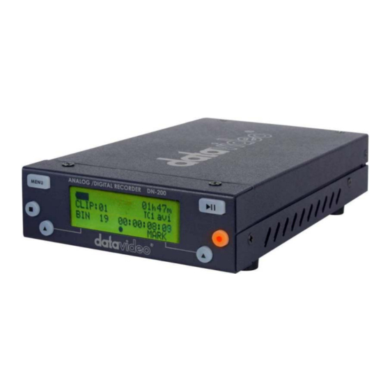
1. Menu Button - Calls up the menu display which is navigated using buttons 6 & 7. 2. Display Panel - Displays the status and set up of the DN-200 unit or if the Menu Button is pressed the DN-200 Menu options. -
Page 8: Rear Panel Connections
The LCD display panel will show “FOR AVHDD MODE PLEASE PRESS MENU”, ignore this message and after a few seconds the Clip Status Display will be shown. The DN-200 is now ready for use as a recorder or playback device. -
Page 9: Dn-200 Menus
DN-200 Menus The DN-200 is a menu driven unit; there are several menus which are used to set up the unit. The menu settings are non-volatile (settings are stored even when the unit is switched off). So general settings, such as date and file type, may only need to be set once. We will look at specific set ups in more detail later on in this manual, but here is an overview of the available menu options. -
Page 10: Record Setup Options
Action taken SET LOOP PLAY When enabled the DN-200 will loop play all clips in the current bin, the playback will continuously loop until stopped. Note that the chosen mode is indicated by an asterisk as well as the presence or absence of the loop play icon on the top line of the Clip Status Display, see page 7. -
Page 11: System Setup Options
Where the recorder is set to operate with one of three signal types, NTSC, PAL or HDV. Note: Changing between signal types will erase the content in all bins and the DN-200 will restart. Backup any content first. The current selection will be marked with an asterisk. -
Page 12: Dn-200 General Setup Notes
Empty the current or all bins The DN-200 is primarily a capture device, as opposed to an archiving device, and it is best to start out with a fresh DN-200 on each project just remember to backup any existing content to computer first. -
Page 13: Normal Recording
2) Automatically, the camera or device connected to the IEEE-1394 port controls the record action. A third way is to issue a record command via the Remote Serial interface or RS-232 port. The DN-200 RS-232 command protocol is listed in this manual from page 19 onwards. -
Page 14: Pausing The Record Process
BNC connection. To cause the recording to pause, that time code must be valid but not moving. If SMPTE time code is not present at all then a DN-200 generated time code is substituted starting at 00:00:00:00 for each bin and incrementing from there in a dropped-frame manner (NTSC only). -
Page 15: Dn-200 Gpi Trigger Connection And Operation
The unit is then ready to playback from this point on the next press of the contact closure button. Press the stop button on the front panel of the DN-200 to end playback of the bin. -
Page 16: Playback
Playback Set up loop play When loop play is enabled and the last frame of the last clip is reached the DN-200 will start over playing from the first frame of the first clip seamlessly. Power on auto play When this option is enabled at power up the DN-200 will begin playing back immediately from the first clip of the last selected bin. -
Page 17: Connection To A Computer In Av Hdd Mode
The NTFS format is fully compatible with PCs and is read compatible with Macs. Its main advantage is that it does not impose a file size limitation to the DN-200 resulting in one file per clip. NTFS’ clip boundary is frame accurate and therefore has perfect correlation with clip numbers in the VTR mode. -
Page 18: Updating Dn-200 Firmware
A PC or Mac computer. The AV HDD mode is where the DN-200 appears to the computer as a Hard Disk Drive (HDD) and not as a video device. The connection to the computer is done via the IEEE-1394 connector. The AVHDD mode is entered by pressing the Menu key within the 5 seconds just after the DN-200 is powered on. -
Page 19: Dn-200 Rs-232 Controller Command Set
Other than the sense command, the unit will respond to all commands affirmatively by sending a three byte acknowledgement (ACK) if the Checksum is valid. If the Checksum is not valid, the DN-200 will ignore the command. Most commands will be responded to within 8 msec. However, a PLAY command from an idle state will result in response delay of up to 700 msec. -
Page 20: System Control
System Control 00h, 11h Device Type request The response is 00, 00 indicating Quick Capture 00h, F1h Next Bin When this command is issued from the Idle state the next bin is selected. If the present bin is 99 then the next bin is 1. -
Page 21: Transport Control
24h, F5h, nn Play to Offset nn Content of the present bin is played at 1x speed starting from present Frame Offset until Frame Offset nn at which point it pauses. Frame Offset nn is 4 bytes and starts with the LSB. This command may be issued from the idle state or any other Play state. -
Page 23: Service And Support
It is our goal to make your products ownership a satisfying experience. Our supporting staff is available to assist you in setting up and operating your system. Please refer to our web site www.datavideo-tek.com for answers to common questions, support requests or contact your local office below.
Need help?
Do you have a question about the DN-200 and is the answer not in the manual?
Questions and answers