
Related Manuals for Fanimation Camview FP6225BL


Summary of Contents for Fanimation Camview FP6225BL
-
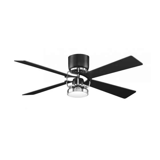
Page 1: Ceiling Fan
The Camview ™ Ceiling Fan Net Weight 7.3 kg (16.08 lbs) Model No. FP6225BL OWNER’S MANUAL READ AND SAVE THESE INSTRUCTIONS... -
Page 2: Important Safety Instructions
Fanimation. 7. Fanimation reserves the right to modify or discontinue any product at any time and may substitute any part under this warranty. 8. Under no circumstances may a fan be returned without prior authorization from Fanimation. The receipt of purchase must ac- company authorized returns and must be sent freight prepaid to Fanimation. -
Page 3: Table Of Contents
Table of Contents Unpacking Instructions................4 . -
Page 4: Unpacking Instructions
– Four Wire Connectors Fanimation. Substitution of parts or accessories not designated for use with this product by Fanimation could – 4 result in personal injury or property damage. Contact your retail store for missing or damaged parts. -
Page 5: Electrical And Structural Requirements
8 - 9 feet above the floor for optimal airflow. Consult your down into the occupied space.Remember to adjust your Fanimation Retailer for optional mounting accessories. thermostat when using your ceiling fan - additional energy and dollar savings could be realized with this simple step! Ceiling fans cool people, not rooms. -
Page 6: How To Hang Your Ceiling Fan
How to Hang Your Ceiling Fan WARNING Ceiling The fan must be hung with at least 7´ of clearance from floor to blades. (Figure 1) WARNING To avoid possible electrical shock, be sure electricity is turned off at the main fuse box before hanging. less than NOTE: If you are not sure if the outlet box is grounded, 7 ft... -
Page 7: How To Wire Your Ceiling Fan - Remote Control
How to Wire Your Ceiling Fan - Remote Control If you feel that you do not have enough electrical wiring NOTE: If fan or supply wires are different colors than indicated, knowledge or experience, have your fan installed by a licensed electrician. -
Page 8: How To Assemble Your Ceiling Fan
How to Assemble Your Ceiling Fan NOTE: This step is applicable after the necessary wiring is completed. (see page 7) 1. Carefully connect the wires with wire connects. (Figure 1) WHITE WIRE FROM SUPPLY BLACK WIRE GREEN WIRE(GROUND) FROM SUPPLY FROM HANGER BRACKET BLACK WIRE FROM FAN... -
Page 9: How To Assemble The Housing And Blade Holder
How to Assemble the Housing and Blade Holder 1. Remove the four screws in the motor assembly. Assemble the housing onto the motor assembly using the four screws and securely tighten. (Figure 1) Housing Figure 1 2. Assemble the blade arm with holder assembly to Motor Assembly Blade Arm with Holder Assembly... -
Page 10: How To Assemble The Light Kit And Blade
How to Assemble the Light Kit and Blade 1. Securely attach the 6-pin switch housing connector to the wiring harness socket within the adapter assembly. (Figure 1) Switch Housing Assembly Figure 1 2. Remove the one of three screws in the switch housing assembly. - Page 11 How to Assemble the Light Kit and Blade (Continued) 5. Insert light bulb into socket. (Figure 5) CAUTION To reduce the risk of fire, use 100-watt max. type T4-minican JD E11 tungsten halogen bulb. Turn off the wall switch and allow the bulb to cool for 10 minutes before relamping.
-
Page 12: How To Operate Your Ceiling Fan
How to Operate Your Ceiling Fan Restore electrical power to the outlet box by turning the electricity on at the main fuse box. (Figure 1) WARNING MAIN FUSE BOX Check to see that all connections are tight, including ground, and that no bare wire is visible at the wire connectors, except for the ground wire. -
Page 13: How To Install Your Remote Control
How to Install Your Remote Control (Option #1) 1. Unthread two screws from the wall switch plate. (Figure 1) 2. Install the control bracket with two #6-32x 3/4” screws. And push the four plastic plug to cover the screw holes. (Including in the control).(Figure 2) Figure 1 Figure 2... -
Page 14: How To Replace Receiver
How to Replace Receiver 1. Remove the four screws in the housing. Retain the four screws for installation Step 7. (Figure 1) Housing Figure 1 2. Carefully pull down the housing. Remove the four screws in the motor assembly from the ceiling bracket CEILING assembly. - Page 15 How to Replace Receiver (Continued) 5. Carefully secure the motor assembly onto the mounting slots on ceiling bracket assembly with the upward-clockwise, quarter-turn twist. (Figure 5) Ceiling Bracket Assembly Motor Assembly Figure 5 6. Secure the motor assembly onto the ceiling bracket assembly using the four screws that was previously removed.
-
Page 16: Trouble Shooting
Trouble Shooting WARNING For your own safety turn off power at fuse box or circuit breaker before trouble shooting your fan. Trouble Probable Cause Suggested Remedy 1. Fuse or circuit breaker blown. 1. Check main and branch circuit fuses or circuit breakers. -
Page 17: Parts List
Parts List Model #FP6225BL Ref. # Description Part # AP622501BL AMA6225BL Housing P522503BL P622514CH Blade Set P622504BL Trim Cover P622507BL AP622509BL AP622510CH AP622512CH Glass P622511OP PPE11B100-C Hand Held Remote Control TR24WH Receiver Hardware Bags Containing: Wire Connectors (4) Insert FINISH CODES (Refer to fan model number located on downrod support) -
Page 18: Exploded-View Illustration
FP6225BL Exploded-View Figure 1 NOTE:... - Page 19 10983 Bennett Parkway Zionsville, IN 46077 Toll Free (888) 567-2055 FAX (866) 482-5215 Outside U.S. call (317) 733-4113 Visit Our Website www.fanimation.com Copyright 2012 Fanimation 2012/08 V.01...