Extron electronics XTRA Series User Manual
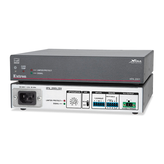
Xtra series half-rack audio power amplifiers
Hide thumbs
Also See for XTRA Series:
- User manual (32 pages) ,
- Setup manual (2 pages) ,
- User manual (23 pages)

Related Manuals for Extron electronics XTRA Series


Summary of Contents for Extron electronics XTRA Series
- Page 1 User Guide Audio Products XTRA Series ™ Half-Rack Audio Power Amplifiers 68-1351-01 Rev. D 07 12...
- Page 2 Safety Instructions • English Warning Power sources • This equipment should be operated only from the power source indicated on the product. This This symbol is intended to alert the user of important operating and mainte- equipment is intended to be used with a main power system with a grounded (neutral) conductor. The third nance (servicing) instructions in the literature provided with the equipment.
-
Page 3: Conventions Used In This Guide
A note draws attention to important information. Specifications Availability Product specifications are available on the Extron website, www.extron.com. Copyright © 2012 Extron Electronics. All rights reserved. Trademarks All trademarks mentioned in this manual are the properties of their respective owners. -
Page 5: Table Of Contents
Amplifier Enters Standby Mode Too Early ........... 20 Limiter/Protect LED Warning Indicators ..21 Over Temp Indicator LED ......21 References ..........Part Numbers and Accessories ......20 Included Parts ..........20 Optional Accessories ........20 XTRA Series • Contents... -
Page 7: Introduction
The XPA 2001 features less than 0.1% total harmonic distortion plus noise, and better than 100 dB signal to noise ratio. ENERGY STAR® qualified amplifier — The XTRA Series of amplifiers are energy efficient products that conserve energy and reduce operating costs. - Page 8 Convection cooled — The XTRA Series of amplifiers are convection cooled without the need for fans, ensuring quiet, reliable operation. Ultra low inrush current - no need for power sequencing — Allows many XTRA Series amplifiers to be powered on simultaneously without overloading power circuits.
-
Page 9: Installation
Installation This section discusses how to install the XTRA Series of audio power amplifiers. Topics that are covered, include: • Application Examples • Mounting the XPA 1002 and XPA 2001 WARNING: Failure to follow these instructions may result in serious injury. -
Page 10: Mounting The Xpa 1002 And Xpa 2001
[Tma = +32 to +122 °F (0 to +50 °C)]. Reduced air flow — Installation of the equipment in a rack should be such that the amount of air flow required for safe operation of the equipment is not compromised. XTRA Series • Installation... -
Page 11: Rack Mounting
1 through 3. Attach the rack shelf to the rack using four 10-32 x ¾” bolts (provided). Insert the bolts through #10 beveled washers, then through the holes in the rack, as shown above. XTRA Series • Installation... -
Page 12: Flexible Conduit Adapter Kit Installation
One EMT adapter plate • One 6-foot long electrical conduit • Three 7.5 feet, 18-gauge spade connector power wires • One UL rated zip tie wrap • Three auxiliary crimp style spade connectors designed for 14- to 16-gauge wires XTRA Series • Installation... -
Page 13: Installing The Flexible Conduit Kit
, 50 0. 5A R /P IT E S IG 0- 24 L IM Figure 5. Removing the Cover Remove the 2 screws holding the hot (line) and neutral wires from the terminal block on the PCB. XTRA Series • Installation... - Page 14 Connect the ground wire, as shown above, to the grounding stud on the bottom of the enclosure using the nut that was removed in step 4. Replace the cover of the XPA by attaching the 8 screws that were removed in step 2. XTRA Series • Installation...
-
Page 15: Operation
Operation This section discusses how to operate the XTRA Series of audio power amplifiers. Topics that are covered, include: • Front Panel Features and Operation • Rear Panel Features and Operation Front Panel Features and Operation OVER TEMP LIMITER/PROTECT SIGNAL... - Page 16 Signal indicator LEDs (channels 1 and 2) — These LEDs (representing input channels 1 and 2) light green only when an input signal is detected on the corresponding channel. SIGNAL NOTE: These LEDs are also located on the rear panel. XTRA Series • Operation...
-
Page 17: Rear Panel Features And Operation
Operation” on page 10 for more details. Signal indicator LEDs — These LEDs light green only when an input signal is detected on the corresponding channel. NOTE: “Front Panel Features and Operation” on page 10 for more details. XTRA Series • Operation... - Page 18 The output power of the XPA 1002 can be effectively doubled by using only one input channel and bridging the output. The XPA 1002 will output “Bridged Mono Output” on 200 watts @ 8 ohms in bridged mode. See page 19 for wiring instructions when bridging the XPA 1002. XTRA Series • Operation...
- Page 19 (full attenuation) to 10 V (maximum volume) with full muting in effect when pin C is connected to ground (pin G). Use the included 3-pin captive screw connector. “Remote Volume Control” on page 17. 50 mA REMOTE VOL/MUTE 50mA STANDBY MUTE 2K OHMS 10K OHMS MUTE SWITCH VOLUME XTRA Series • Operation...
- Page 20 The XPA 1002 will output “Bridged Mono Output” on 200 watts at 8 ohms in bridged mode. See page 19 for wiring instructions when bridging the XPA 1002. XTRA Series • Operation...
- Page 21 ATTENTION: Failure to follow these instructions may result in damage to the unit. Do not tie channel outputs 1 and 2 to each other or to ground. Doing so will short out the outputs and/or damage the amplifier. XTRA Series • Operation...
- Page 22 Otherwise, it should be left on. • The high-pass filter toggle switch may be labeled one of two ways. The wiring and function are the same, whichever way your product is labeled. XTRA Series • Operation...
-
Page 23: Remote Volume Control
NOTE: All nominal levels are at ±10%. REMOTE 50mA Extron STP 22 Cable Black Ground 50 mA VOL/MUTE VOLUME MUTE STANDBY VCM 100 Figure 8. Pinout Diagram for VCM 100 MAAP Connection to XPA Remote Connector XTRA Series • Operation... -
Page 24: Controlling Multiple Amplifiers With One Volume Controller
Figure 9. Regulating Multiple Amplifiers with a Single Volume Controller NOTE: The 10 V pin of the volume controller connects to the first XPA Half-Rack unit only. There are no jumper wires linking it to subsequent amplifiers. XTRA Series • Operation... -
Page 25: Bridged Mono Output
During bridged mono output, the + output To 8 Ohm Minimum from output channel 1 becomes the positive Speaker Load terminal and the + output from channel 2 becomes the negative terminal Figure 10. Bridging the Output of the XPA 1002 XTRA Series • Operation... -
Page 26: Troubleshooting
The output signal level of the Amber intermittently early. source may be too low to cross the signal detection threshold of the amplifier (see amplifier specifications for details). Increase the signal level of the source until the signal LED lights consistently. XTRA Series • Troubleshooting... -
Page 27: Limiter/Protect Led Warning Indicators
The LED turns off ventilation and airflow. after the amplifier cools down • Avoid placing equipment on top sufficiently. of the amplifier. • Verify that the operating temperature is within the specified range. XTRA Series • Troubleshooting... -
Page 28: References
References This section discusses the part numbers and accessories for the XTRA Series of half-rack audio power amplifiers. Part Numbers and Accessories Included parts Included parts Replacement part number XPA 1002 two-channel power amplifier 60-849-01 XPA 2001-70V single-channel power amplifier... -
Page 29: Extron Warranty
Extron Electronics makes no further warranties either expressed or implied with respect to the product and its quality, performance, merchantability, or fitness for any particular use. In no event will Extron Electronics be liable for direct, indirect, or consequential damages resulting from any defect in this product even if Extron Electronics has been advised of such damage.
Need help?
Do you have a question about the XTRA Series and is the answer not in the manual?
Questions and answers