Extron electronics XTRA Series User Manual
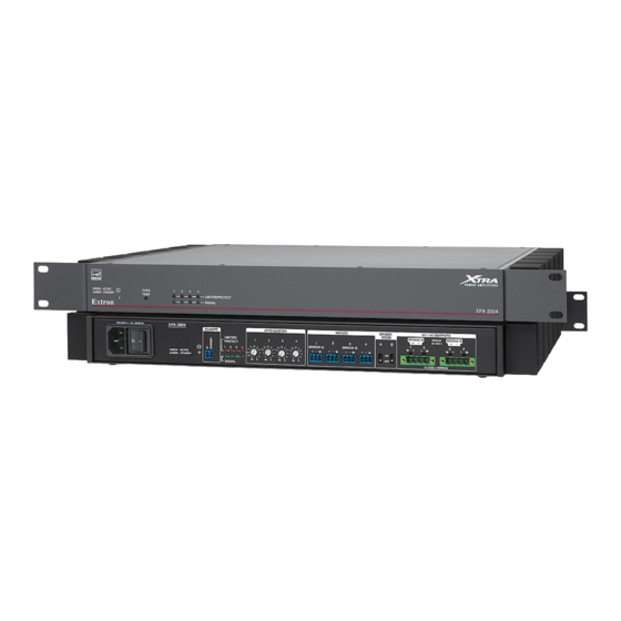
Full-rack 2- and 4-channel audio power amplifiers
Hide thumbs
Also See for XTRA Series:
- User manual (32 pages) ,
- Setup manual (2 pages) ,
- User manual (29 pages)

Related Manuals for Extron electronics XTRA Series


Summary of Contents for Extron electronics XTRA Series
- Page 1 XTRA Full Rack Series: ™ XPA 2004, XPA 4002, XPA 4002-70V Full-Rack 2- and 4-Channel Audio Power Amplifiers User Guide Audio Products 68-783-01, Rev. H 01 24...
- Page 2 Safety Instructions Safety Instructions • English Instructions de sécurité • Français AVERTISSEMENT : Ce pictogramme, , lorsqu’il est utilisé sur le WARNING: This symbol, , when used on the product, is intended to produit, signale à l’utilisateur la présence à l’intérieur du boîtier du produit alert the user of the presence of uninsulated dangerous voltage within the d’une tension électrique dangereuse susceptible de provoquer un choc product’s enclosure that may present a risk of electric shock.
- Page 3 • 安全说明 简体中文 警告: 产品上的这个标志意在警告用户, 该产品机壳内有暴露的危险 电压, 有触电危险。 注意: 产品上的这个标志意在提示用户, 设备随附的用户手册中有重 要的操作和维护(维修)说明。 关于我们产品的安全指南、遵循的规范、EMI/EMF 的兼容性、无障碍使 用的特性等相关内容, 敬请访问 Extron 网站, www.extron.com,参见 Extron 安全规范指南,产品编号 68-290-01 。 安全記事 • 繁體中文 안전 지침 • 한국어 경고: 이 기호 가 제품에 사용될 경우, 제품의 인클로저 내에 있는 警告: 若產品上使用此符號,...
- Page 4 FCC Class B Notice NOTE: This device complies with part 15 of the FCC rules. Operation is subject to the following two conditions: (1) This device may not cause harmful interference, and (2) This device must accept any interference received, including interference that may cause undesired operation. This equipment has been tested and found to comply with the limits for a Class B digital device, pursuant to part 15 of the FCC rules.
- Page 5 Conventions Used in this Guide Notifications The following notifications are used in this guide: DANGER: Will result in serious injury or death. PELIGRO: Resultará en lesiones graves o la muerte: DANGER: Entraînera des blessures graves ou la mort. WARNING: Potential risk of severe injury or death. ADVERTENCIA: Riesgo potencial de lesiones graves: AVERTISSEMENT : Risque potentiel de blessure grave ou de mort.
-
Page 6: Table Of Contents
Limiter/Protect LED Warning Indicators .... 16 Over Temp Indicator LED ........16 Reference Information ........17 Mounting the XTRA Series Power Amplifiers ..17 Tabletop Use ............. 17 UL Guidelines for Rack Mounting ..... 17 Consignes UL pour le montage en rack .... 18 Rack Mounting .......... - Page 7 XTRA Full Rack Power Amplifier Series • Contents...
-
Page 8: Introduction
_________________________________ About this User Guide This user guide contains information about the Extron XTRA series of full rack width audio power amplifiers. The Extron XTRA™ Series is a family of 1U convection cooled power amplifiers with mono, stereo, and multi-channel outputs. These professional grade amplifiers deliver from 200 to 800 watts of continuous output power and are available for low and high impedance applications. - Page 9 It generates substantially less heat than conventional power amplifiers, making it ideal for rack-mount applications. • — Allows multiple XTRA Series amplifiers to be Ultra low inrush current - no need for power sequencing powered on simultaneously without overloading power circuits. This eliminates the need for power sequencing.
-
Page 10: Installation
Installation ______________________________ This section discusses how to install the XTRA Series of full rack power amplifiers. WARNING: Installation and service must be performed by authorized personnel only (see Guidelines for Rack Mounting on page 17). AVERTISSEMENT : L’installation et l’entretien doivent être effectués par le personnel autorisé uniquement... - Page 11 Equipment Room Rack Extron XPA 2004 OVER GREEN - ACTIVE AMBER - STANDBY TEMP LIMITER / PROTECT Power Ampli er SIGNAL XPA 2004 Extron GREEN - ACTIVE OVER LIMITER / PROTECT AMBER - STANDBY TEMP SIGNAL XPA 4002 XPA 2004 Extron GREEN - ACTIVE OVER...
-
Page 12: Installing The Xpa Amplifier
2. Mount the amplifier — For diagrams of typical application examples, see Application Examples starting on page 3. For further mounting instructions, see Mounting the XTRA Series Power Amplifiers starting on page 17). 3. Wire the source(s) — Wire the input to the 3.5 mm input connectors of the amplifier (see... - Page 13 4-pole (8 ohm or 4 ohm) output connector wiring: Do not tin the wires! Figure 6. Wiring 4-pole Connectors ATTENTION: • Do not short the + and outputs to each other. Doing so may damage the amplifier. • Ne pas créer un court circuit entre les sorties + et au risque d’endommager l’amplificateur.
- Page 14 6. Set the high pass filter, XPA 4002-70V — Use a small screwdriver to toggle this switch between off (no filtering) and 80 Hz (default). • XPA 4002-70V has two switches, one for each output channel. • Setting the switch to 80 Hz prevents the saturation of speaker input transformers by low frequency signals.
-
Page 15: Operation
Operation __________________________ This section discusses how to operate the XPA power amplifiers. Topics that are covered, include: • Front Panel Features and Operation • Troubleshooting • Rear Panel Features and Operation Front Panel Features and Operation The XPA power amplifier front panels are shown below. OVER GREEN - ACTIVE LIMITER / PROTECT... -
Page 16: Rear Panel Features And Operation
Rear Panel Features and Operation The XPA power amplifier rear panels are shown below. 100-240V 1.5A, 50-60 Hz XPA 2004 ATTENUATION REMOTE INPUTS BRIDGE 8 / 4 OUTPUTS MODE BRIDGE A BRIDGE BRIDGE B LIMITER/ 8 ONLY PROTECT (BRIDGE A) (BRIDGE B) GREEN - ACTIVE AMBER - STANDBY... - Page 17 (see figure 8 in the previous page) — These LEDs Limiter/Protect indicator LEDs (channels 1, 2, 3, and 4) (representing output channels 1, 2, 3, and 4) light red in the following circumstances: • When audio clipping occurs, the corresponding LED turns on while the amplifier is limiting. •...
- Page 18 — (see figure 8 on page 9) Use a small High pass filter toggle switch, XPA 4002-70V screwdriver to toggle this recessed two-position toggle switch that alternates between Off (no filtering) and 80 Hz. The XPA 4002-70V has two switches, one for each output channel. Setting the switch to 80 Hz prevents the saturation of the speaker input transformers by low frequency signals.
- Page 19 — (see figure 8 on page 9) Wire the included 4-pole, 5 mm screw lock captive Stereo audio output connector screw connector to output 2-channel (XPA 4002) or 4-channel (XPA 2004) audio. Observe the correct polarities for each channel. See steps 1 and 2 on the following page. Output is designed to power 4 or 8 ohm speakers and is rated at 200 watts (400 watts, XPA 4002) with a 4-ohm speaker load, or 100 watts (200 watts, XPA 4002) with an 8-ohm speaker load, per channel.
-
Page 20: Bridged Mode Output
Bridged Mode Output XPA 4002 bridged mono output speaker wiring In bridged mode, the output mode toggle switch for Input 1 must be set to the BRIDGE MODE 8 / 4 OUTPUTS bridged (up) position. BRIDGE BRIDGE 8 ONLY For Input 1: The channel 1 + output terminal becomes the bridged + output terminal and the channel 2 + output terminal becomes the bridged “-”... - Page 21 XPA 2004 bridged mono output speaker wiring In bridged mode, the output mode toggle switches for Input 1 (A) or Input 3 (B) or both must be set to the bridged (up) position (see figure 14). For Input 1: The channel 1 + output terminal becomes the bridged + output terminal and the channel 2 + output terminal becomes the bridged - output terminal.
-
Page 22: Troubleshooting
Troubleshooting The front and rear panels have LED warning indicators, as described in the following diagnostic information. Amplifier Fails to Exit Standby Mode Promptly The input channel (channels 1, 2, 3, and 4) Signal LED lights green per indicated input channel when an input signal is detected. -
Page 23: Limiter/Protect Led Warning Indicators
Limiter/Protect LED Warning Indicators The output channel ( channels 1, 2, 3, and 4) Limiter/Protect LED lights red per indicated output channel as shown in the following diagnostic information. LED State Problem Description Problem Solution Blinks Audio clipping is occurring and the Limiter/ Reduce the power output to avoid overdriving Protect LED is blinking. -
Page 24: Reference Information
Reference Information ___________________________________________________________ This section discusses the mounting instructions for the XPA seires of power amplifiers. Mounting the XTRA Series Power Amplifiers The XPA power amplifiers can be set on a table or mounted on a rack shelf. Tabletop Use Four self-adhesive rubber feet are included with the audio amplifier. -
Page 25: Consignes Ul Pour Le Montage En Rack
(ex. : les multiprises). Rack Mounting The XTRA series of audio amplifiers are housed in rack-mountable metal enclosures with pre-attached mounting ears for standard 19-inch racks. Mount the amplifier as follows: 1. Disconnect all cables and power sources from the amplifier. - Page 26 Rack Mounting Ventilation Excessive heat can decrease the optimal lifetime of the power amplifier. An over temp indicator LED on the front panel of the amplifier lights red whenever the recommended operating temperature has been exceeded (see Front Panel Features and Operation on page 8).
-
Page 27: Extron Warranty
Extron Electronics makes no further warranties either expressed or implied with respect to the product and its quality, performance, merchantability, or fitness for any particular use. In no event will Extron Electronics be liable for direct, indirect, or consequential damages resulting from any defect in this product even if Extron Electronics has been advised of such damage.
Need help?
Do you have a question about the XTRA Series and is the answer not in the manual?
Questions and answers