Extron electronics XTRA Series Setup Manual
Half-rack audio power amplifiers
Hide thumbs
Also See for XTRA Series:
- User manual (32 pages) ,
- User manual (23 pages) ,
- User manual (29 pages)
Table of Contents
Advertisement
Quick Links
XTRA
Series Half-Rack Audio Power Amplifiers • Setup Guide
™
(XPA 1002, XPA 1002 Plus, XPA 1002-70V, XPA 1002-100V, XPA 2001-70V, XPA 2001-100V)
WARNING: Installation and service must be performed by experienced personnel only.
AVERTISSEMENT : L'installation et l'entretien doivent être effectués par le personnel autorisé uniquement.
This guide provides startup instructions for an experienced installer to set up and operate the XPA 1002 or XPA 2001 series audio
power amplifiers. All references are to the XTRA Series Half-Rack user guide which can be found on www.extron.com.
Step 1 — Powering Down Equipment
Be sure that power to the amplifier is turned off first.
NOTE:
Adjust the audio level to = (full attenuation) prior to powering the amplifier in step 7.
Turn off all other equipment and disconnect the power cables. Verify that the amplifier is disconnected from the power source
before proceeding.
Step 2 — Mounting and Applications
For diagrams of typical application examples, see Application Examples in the user guide. For further mounting instructions, see
Mounting the XTRA Series Amplifier in the user guide.
Step 3 — Captive Screw Audio Cable Wiring
NOTE:
Control signal ground pins may be labeled as , , or "G". Audio ground pins may be labeled as
The wiring and function are the same, whichever way your product is labeled.
Wire the source output to the amplifier input 3.5 mm captive screw connectors as shown in the following illustration.
NOTE:
The output power of the XPA 1002 and XPA 1002 Plus can be effectively doubled by using only one source channel
and bridging the output. The XPA 1002 and XPA 1002 Plus output 200 watts @ 8 ohms in bridged mode (see Bridged
Mono Output in the user guide for wiring instructions when bridging the XPA 1002 or XPA 1002 Plus).
Tip
Sleeve
Unbalanced Dual Mono Input
XPA 1002, XPA 1002 Plus
XPA 1002-70V/100V
NOTE:
For mono input on the XPA 1002-70V/100V and 2001-70V/100V models, only the left channel needs to be wired; no
jumpering to the right channel is needed. The left and right inputs of these models are summed internally to mono.
Step 4 — Speaker Wiring
Wire the speakers to the output connector of the amplifier using the included 4 pole
(XPA 1002, XPA 1002 Plus, XPA 1002-70V/100V) or 2 pole (XPA 2001-70V/100V) captive
screw connector as shown to the right.
Tip
Tip
Sleeve
Ring
Sleeve
Tip
Sleeve
Balanced Dual Mono Input
Unbalanced Stereo Input
XPA 1002, XPA 1002 Plus
XPA 1002-70V/100V
Tip
Ring
Sleeves
Tip
Ring
Balanced Stereo Input
1
2
XPA 1002,
XPA 1002 Plus
XPA 1002-70V/100V
or .
Do not tin the wires!
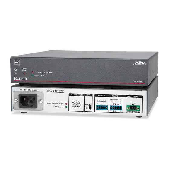
XPA 2001 Series
Advertisement
Table of Contents

Related Manuals for Extron electronics XTRA Series


Summary of Contents for Extron electronics XTRA Series
- Page 1 This guide provides startup instructions for an experienced installer to set up and operate the XPA 1002 or XPA 2001 series audio power amplifiers. All references are to the XTRA Series Half-Rack user guide which can be found on www.extron.com.
- Page 2 Extron USA - West Extron USA - East +65.6383.4664 FAX +81.3.3511.7656 FAX +86.21.3760.1566 +971.4.299.1800 +82.2.3444.1575 FAX +31.33.453.4040 +971.4.299.1880 FAX +91.80.3055.3777 +1.714.491.1500 +1.919.850.1000 +1.714.491.1517 FAX +1.919.850.1001 FAX +31.33.453.4050 FAX +91.80.3055 3737 68-2354-50 Rev. B © 2014 Extron Electronics All rights reserved. www.extron.com 06 14...
Need help?
Do you have a question about the XTRA Series and is the answer not in the manual?
Questions and answers