
Related Manuals for Alcatel-Lucent 7210


Summary of Contents for Alcatel-Lucent 7210
- Page 1 7210 S ERVICE CCESS WITCH (SAS) E THERNET NSTALLATION UIDE November 2013 Document Part Number: 93-0245-01-13 *93-0245-01-13*...
- Page 2 Copyright 2013 Alcatel-Lucent All rights reserved. No portion of this document may be reproduced in any form or means without prior written permission from Alcatel-Lucent. Information in this document is proprietary and confidential to Alcatel. The information in this document is subject to change. All trademarks and registered trademarks are the property of the respective owners.
-
Page 3: Table Of Contents
System Buttons and Switches ............28 Installing the 7210 SAS-E Site Preparation . - Page 4 Booting a 7210 SAS-E From the Network ........
-
Page 5: Ist Of
7210 SAS-E System LEDs and Buttons ........ - Page 6 List of Tables Page 6 7210 SAS E Ethernet Service Switch...
- Page 7 7210 SAS-E Boot Process ........
- Page 8 List of Figures Page 8 7210 SAS-E Installation Guide...
-
Page 9: Preface
Alcatel-Lucent 7210 Service Access Switch (SAS-E) , and instructions to install and configure the TiMOS software. Each 7210 SAS-E router is shipped with rack-mounting brackets, a console cable, power cord (AC or DC), and rubber feet. Warnings and Notes Observe the warnings and notes to avoid injury or router damage during installation and maintenance. -
Page 10: Table 1: Information Symbols
Class 1 Laser Product Technical Support If you purchased a service agreement for your 7210 SAS-E and related products from a distributor or authorized reseller, contact the technical support staff for that distributor or reseller for assistance. If you purchased an Alcatel-Lucent service agreement, contact technical... -
Page 11: 7210 Sas-E Overview
7210 SAS-E Overview This chapter describes the 7210 SAS-E features and includes the following sections: • "Switch Features" on page 12 • "Switch Architecture" on page 13 • "Features" on page 14 • "Hardware Description" on page 15 7210 SAS-E Installation Guide... -
Page 12: Switch Features
Switch Features Switch Features The 7210 SAS-E is a multilayer service-aware Layer 2 switch. It supports up to 24 connections including 12 100/1000 fiber-optic SFP ports and 12 10/100/1000Base-T copper SFP ports. The 7210 SAS-E has one 10/100BASE-TX management port for dedicated management access. -
Page 13: Switch Architecture
7210 SAS-E Overview Switch Architecture The 7210 SAS-E employs a wire-speed, non-blocking switching fabric. This permits simultaneous wire-speed transport of multiple packets at low latency on all ports. The switch also features full- duplex capability on all ports, that effectively doubles the bandwidth of each connection. -
Page 14: Features
DB-15 interface on the front panel • Hot-swappable, redundant, load sharing AC or DC power and fan modules Connectivity The 7210 SAS-E includes the following connectivity features: • 100/1000 fiber-optic SFP ports and 10/100/1000Base-T copper SFP ports full-duplex connections. •... -
Page 15: Hardware Description
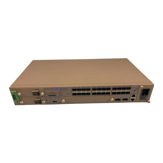
7210 SAS-E Overview Hardware Description Figure 2: 7210 SAS E Front Panel Table 2: 7210 SAS-E Front Panel Features Description Ground and DC power connection Additional chassis ground point Power trays Power tray one to fit power supply 3a Power tray two to fit power supply 3b... -
Page 16: Ethernet Interfaces
The primary ground point is on the rear of the chassis. Ethernet Interfaces The 7210 SAS-E provides 12 100/1000 fiber-optic SFP ports. Each fiber-optic port can be used for a direct connection to a subscriber’s Customer Premises Equipment (CPE), or as an uplink to another aggregation node. -
Page 17: Alarm Interface Port
External alarm input 4 (the positive side of the alarm input) ALARM_IN3_EXT_P External alarm input 3 (external relay dry contact closure to pin 13) ALARM_IN2_EXT_P External alarm input 2 (external relay dry contact closure to pin 14) 7210 SAS-E Installation Guide Page 17... -
Page 18: Table 17: Alarm Interface Port Pinouts
External alarm input 3 (external relay dry contact closure from pin 6) ALARM_IN2_EXT_RTN External alarm input 2 (external relay dry contact closure from pin 7) ALARM_IN1_EXT_RTN External alarm input 1 (external relay dry contact closure from pin 8) Page 18 7210 SAS-E Installation Guide... -
Page 19: Power Modules
7210 SAS-E Overview Power Modules 7210 SAS-E 24F variant provides three power module options: -48V, +24V and universal AC. See Figure 3 for an illustration of the power modules. For specifications on the power supply modules and external input power requirements, see "Connecting to a Power Source"... - Page 20 The -48V/+24V/AC LEDs on the left indicate the status of external power. The +12V LED on the right indicates the status of the internal power conversion process. You must use AC and/or DC power supplies with your 7210 SAS-E. AC and DC power Note: supplies can be used simultaneously.
-
Page 21: Dc Power Source Failure Detection
The 7210 platform provides capability to detect DC power source (-48V or +24V source) failure. The 7210 chassis allows two DC power sources to be connected to the chassis. If the system detects that a DC power source has failed, it raises a critical alarm (the Critical LED is lit and the Critical Alarm output pin is triggered) and the system's status LED turns amber and blinks.. -
Page 22: Table 5: Power Source Failure Detection Capability
None No power to system Available Available Available Failed PS2 input failure / PS2 output OK Failed Available Input failure / Not detected Failed Failed PS2 input failure / PS2 output failure Available Available Page 22 7210 SAS-E Installation Guide... - Page 23 Top Slot Bottom (Yes/No) Failed) Failed) (PS1) Slot (PS2) Available Failed Input failure / Not detected Failed Available PS1 input failure / PS1 output OK Failed Failed PS1 input failure / PS1 output OK 7210 SAS-E Installation Guide Page 23...
-
Page 24: Usb Port
Allow at least three inches of clearance on the side of the rack to ensure proper airflow intake cooling system. The fan trays must be in place before the chassis is powered on. Figure 4: Fan Tray Page 24 7210 SAS-E Installation Guide... -
Page 25: Figure 5: Removing And Replacing The Fan Tray And Air Filter
Step 3 air filter is flush with the rear of the fan tray. Replace the fan tray and tighten the captive screws. Step 4 Figure 5: Removing and Replacing the Fan Tray and Air Filter 7210 SAS-E Installation Guide Page 25... -
Page 26: System Leds And Buttons
LEDs and buttons, Table 6 for key descriptions, and Table 7 for alarm descriptions. Figure 6: System LEDs and Buttons Table 6: 7210 SAS-E System LEDs and Buttons Description Alarm LEDs Alarm Cut Off button Reset button 100/1000 fiber-optic SFP port LEDs... -
Page 27: System And Port Leds
1/1/13 – 1/1/24 – Fixed Copper ports Flashing Green Flashing indicates activity on the port. The link is down. Figure 7 for an illustration of two ports and their corresponding LEDs. See Table 10 descriptions. 7210 SAS-E Installation Guide Page 27... -
Page 28: System Buttons And Switches
Button/Switch Condition Status Power Module Switch Standby mode if switch is connected to a power source. AC or DC power is applied to the switch. ACO (Alarm Cut Off) Not pushed Normal operating mode. Page 28 7210 SAS-E Installation Guide... - Page 29 7210 SAS-E Overview Table 10: Front Panel Buttons and Switches Button/Switch Condition Status Reset (Recessed) Not pushed Normal operating mode. To reset hardware, follow reset procedure mentioned in "Restarting the Router" on page 7210 SAS-E Installation Guide Page 29...
- Page 30 Hardware Description Page 30 7210 SAS-E Installation Guide...
-
Page 31: Installing The 7210 Sas-E
Installing the 7210 SAS-E This chapter describes site preparation and installation of your 7210 SAS-E and includes the following sections: • "Site Preparation" on page 32 • "Installing Your Switch" on page 34 7210 SAS-E Installation Guide Page 31... -
Page 32: Site Preparation
Site Preparation Selecting a Site You can mount the 7210 SAS-E in a standard 19-inch equipment rack or on a flat surface. When mounting on a flat surface, ensure that the four rubber feet are installed on the bottom of the box. -
Page 33: Equipment Checklist
• Make sure you only use SFPs and XFPs that are supported by Alcatel-Lucent. Equipment Checklist After unpacking your switch, check the contents to make sure all the components are present. -
Page 34: Installing Your Switch
Attach the brackets to the device using the screws provided in the Bracket Mounting Kit. See Figure Figure 8: Attaching the Brackets Mount the 7210 SAS E in the rack, using four rack-mounting screws (not Step 2 provided). See Figure... -
Page 35: Installing The 7210 Sas-E
Installing the 7210 SAS-E Figure 9: Installing the Switch in a Rack If you are installing a single switch, proceed to "Grounding the Chassis" on Step 3 page Step 4 If installing multiple switches, mount them in the rack, one below the other, in any order. -
Page 36: Desktop Or Shelf Mounting
If you are installing a single switch, proceed to "Grounding the Chassis" on page If you are installing multiple switches, attach four adhesive feet to each Step 4 switch. Place each device squarely on top of the one below, in any order. Page 36 7210 SAS-E Installation Guide... -
Page 37: Grounding The Chassis
Installing the 7210 SAS-E Grounding the Chassis Before powering on the switch, ground the switch to earth as described below. Ensure that the rack on which the switch is to be mounted is properly Step 1 grounded. Step 2 Ensure that you have made a suitable electrical connection to the grounding point on the rack. -
Page 38: Connecting To A Power Source
AC power module is installed. If you have installed both primary and redundant power supply modules, Step 5 verify that the LEDs on both modules are lit as indicated in the preceding step. Page 38 7210 SAS-E Installation Guide... -
Page 39: Connecting To Dc Power
Installing the 7210 SAS-E Connecting to DC Power The 7210 SAS-E chassis supports the -48V and +24V DC power modules. Hence, the steps below are applicable for either the -48V or the +24V DC power modules. Below the DC power entry block is an additional chassis ground point for attaching a Notes: DC power chassis ground if required by local electrical codes. -
Page 40: Figure 11: Connecting To A -48 Vdc Power Source
Figure 12 illustrates how to connect a +24 VDC power source to the chassis: Ground (A)(Pin 1) +24V (A)(Pin 2) Ground (B)(Pin 1) +24V (B)(Pin 2) Figure 12: Connecting to a +24 VDC Power Source Page 40 7210 SAS-E Installation Guide... -
Page 41: Connecting To The Console Port
Installing the 7210 SAS-E WARNING: If the power leads are plugged into the wrong holes, the power supply will not work properly and may damage the switch. After the power source is tuned on, set the power button on the front of the Step 5 power supply module to the ON position (marked “—... - Page 42 Installing Your Switch Page 42 7210 SAS-E Installation Guide...
- Page 43 This chapter describes how to replace Small Form Factor Pluggable (SFP) ports that support these devices. • "Warnings and Notes" on page 44 • "Installation Preparation" on page 45 7210 SAS-E Installation Guide Page 43...
-
Page 44: Warnings And Notes
• Do not remove the dust cover on the connector until you are ready to install the SFP. Always replace the the dust cover when the SFP is removed. Notes: • Discard SFPs according to all local laws and regulations. • SFPs are keyed to prevent incorrect insertion. Page 44 7210 SAS-E Installation Guide... -
Page 45: Installation Preparation
Blow dry the ferrule with compressed air and inspect for lint. Do not insert the compressed air nozzle into the receptacle when blowing out. Locking Mechanisms Alcatel-Lucent SFPs can use different lock and release methods. Possible lock and release mechanisms include: •... -
Page 46: Installing Sfps
Place the SFP on an anti-static mat or in an electro-static bag. Step 3 Install an SFP replacement or re-insert the plug. Step 4 Connect the network cable or place a safety cap over the optical transceiver. Step 5 Page 46 7210 SAS-E Installation Guide... -
Page 47: Configuring The 7210 Sas-E
Configuring the 7210 SAS-E This chapter describes how to configure your 7210 SAS-E and contains the following sections: • "Diagnostics" on page 48 • "Initializing the System and Downloading Software" on page 49 • "Establishing Router Connections" on page 66 •... -
Page 48: Diagnostics
Major: OFF • Fan: OFF • Status: Steady GREEN If any of the above LEDs shows a different state, reset the hardware using reset procedure mentioned in "Restarting the Router" to let the system boot. Page 48 7210 SAS-E Installation Guide... -
Page 49: Initializing The System And Downloading Software
Timos available in the flash. Booting a 7210 SAS-E in the Lab There are several ways to boot the 7210 SAS-E from the network. User can choose to boot the device using one of the following options: •... -
Page 50: Booting A 7210 Sas-E Using The Image On Flash (With The Image Shipped By Factory)
Cable that connects the console port of SAS-E to the serial port of PC Connect the 7210's console port to serial port of the PC and then power on the 7210. The system will start booting up with messages on the console similar to those shown below. - Page 51 Configuring the 7210 SAS-E uplinkB-port 1/1/2 uplinkB-address 0 uplinkB-vlan 0 #System Settings: wait 3 persist off console-speed 115200 Hit a key within 2 seconds to change boot parameters... Press any key. Enter password to edit the Boot Options File Or CTRL-D to exit the prompt Password: The default password is ‘password’.
- Page 52 The SYS LED will be Green when the device has successfully completed the boot Note: process and is running normally. The default username and password are admin. Log into the 7210 SAS-E. To establish either console connection or Telnet connection to the router after successful boot, please see "Establishing Router Connections"...
-
Page 53: Booting A 7210 Sas-E From The Network
Configuring the 7210 SAS-E Booting a 7210 SAS-E From the Network There are several ways to boot the 7210 SAS-E from the network. User has options to use one of the front panel ports (refered to as uplinkA and uplinkB in the display... -
Page 54: Default Settings
The default password is password. You must supply some required Boot Options. At any prompt, you can type: "restart" - restart the query mode. "reboot" - reboot. "exit" - boot with with existing values. Page 54 7210 SAS-E Installation Guide... - Page 55 Configuring the 7210 SAS-E "diag" - enter the diag shell. "reset" - reset the bof and reboot. Press ENTER to begin, or 'flash' to enter firmware update... Press Enter. Software Location ----------------- You must enter the URL of the TiMOS software.
- Page 56 Enter the new uplinkA port number for Boot Interface Management: Enter the port which it connected to the network (for example, 1/1/24). You need to assign an IP address for this port. The IP address should be entered in standard Page 56 7210 SAS-E Installation Guide...
- Page 57 Configuring the 7210 SAS-E dotted decimal form with a network length. example: 192.168.1.169/24 Or type "0" to obtain IP address and static route through DHCP. Existing IP address and static routes will be deleted. uplinkA port is configured to obtain IP address and static route through dhcp.
- Page 58 115200 Do you want to overwrite cf1:/bof.cfg with the new settings? (yes/no): Type yes and press Enter. The 7210 SAS-E should boot now. Primary image location: ftp://*:*@10.10.170.22/./images/both.tim Initializing uplinkA port using IP addr 10.135.4.172. Page 58 7210 SAS-E Installation Guide...
- Page 59 Executing TiMOS image at 0x100000 … After the 7210 SAS-E boots up, you should see the following prompt: All rights reserved. All use subject to applicable license agreements. Built on Wed Jul 15 17:18:37 IST 2009 by builder in /builder/ws/1.0B1/sultan Login: The default username and password are admin.
-
Page 60: Using The Out-Of-Band Ethernet Management Port To Boot 7210 From The Nework
Enter the IP address and mask that the device should use (for example, 10.135.4.172/ 24). Since the FTP server is on a different subnet, you will have to enter IP routing information using the Out-of-Band Ethernet Management port to boot 7210 from the nework. Network Configuration... -
Page 61: Configuring The 7210 Sas-E
Configuring the 7210 SAS-E prefix/mask next-hop ip-address example: 192.168.0.0/16 next-hop 192.168.1.254 Would you like to add a static route? (yes/no) yes Enter ip route: Enter a static route to the FTP server's subnet (for example, 10.10.170.0/24 next-hop 10.135.4.1) at the prompt. -
Page 62: Downloading The Timos Software To The Internal Flash
If you want to boot the SAS-E from the internal flash, you will have to copy the image there. If you have used the uplinkA or uplinkB port to boot the 7210, use any of the network ports for IP connectivity and follow the procedure given below to configure an IP interface and a route. - Page 63 Configuring the 7210 SAS-E If you have used the out-of-band ethernet management port, then you do not need to configure the IP interface. Instead jump to the step "Check IP connectivity" below and continue from there Change the mode of the connected port to 'access uplink' A:SN12# configure port 1/1/24 A:SN12>config>port#...
- Page 64 Saving BOF ..Completed. A:SN12# admin save Writing file to cf1:\config.txt Saving configuration ..Completed. A:SN12# Copy the TiMOS image from the FTP server to the flash:/ A:SN12# file copy ftp://<user>:<passwd>@10.10.170.22/./images/both.tim cf1:/both.tim Copying file ftp://<user>:<passwd>@10.10.170.22/./images/both.tim... Page 64 7210 SAS-E Installation Guide...
- Page 65 Configuring the 7210 SAS-E 1 file copied. A:SN12# Configure the BOF to pick up the image from internal flash: A:SN12# bof primary-image cf1:/both.tim *A:SN12# bof save Writing BOF to cf1:/bof.cfg Saving BOF ..Completed. A:SN12# Reboot the SAS-E. The device will pick up both the image and the configuration from the internal flash.
-
Page 66: Establishing Router Connections
Establish the connection by pressing the Enter key a few times on your Step 3 terminal keyboard. At the router prompt, enter the login and password. Step 4 The default login is admin The default password is admin Page 66 7210 SAS-E Installation Guide... -
Page 67: Telnet Connection
The 7210 SAS-E must have a management IP interface configured with an IP address. Each 7210 SAS-E is limited to a total of seven inbound/outbound Telnet or SSH sessions to guarantee that either inbound or outbound sessions will be available. -
Page 68: Running Telnet
The 7210 SAS-E must have a management IP address. The IP address is manually configured. Running Telnet Once the IP parameters are configured, you can access the CLI command line with a Telnet connection. -
Page 69: Restarting The Router
Configuring the 7210 SAS-E Restarting the Router To reset the node, use the following procedure: Press and hold the Alarm Cut Off (ACO) button. Step 1 Press the Reset button for a minimum of 10 seconds before releasing the Step 2 Reset button. - Page 70 Restarting the Router Page 70 7210 SAS-E Installation Guide...
-
Page 71: Troubleshooting
This chapter describes troubleshooting methods and procedures and includes the following sections: • "Diagnosing Switch Indicators" on page 72 • "Power and Cooling Problems" on page 73 • "Installation" on page 74 • "In-Band Access" on page 75 7210 SAS-E Installation Guide Page 71... -
Page 72: Diagnosing Switch Indicators
• Verify that the proper cable type is used and its length does not exceed specified limits. • Check the adapter on the attached device and cable connections for possible defects. Replace the defective adapter or cable if necessary. Page 72 7210 SAS-E Installation Guide... -
Page 73: Power And Cooling Problems
However, if the unit powers off after running for a while, check for loose power connections, power losses or surges at the power outlet, and verify that the fans on the unit are unobstructed and running prior to shutdown. 7210 SAS-E Installation Guide Page 73... -
Page 74: Installation
Verify that all system components have been properly installed. If one or more components appear to be malfunctioning (such as the power cord or network cabling), test them in an alternate environment where you are sure that all the other components are functioning properly. Page 74 7210 SAS-E Installation Guide... -
Page 75: In-Band Access
NOTE: The management agent can accept up to four simultaneous Telnet sessions. If the maximum number of sessions already exists, an additional Telnet connection will not be able to log into the system. 7210 SAS-E Installation Guide Page 75... - Page 76 In-Band Access Page 76 7210 SAS-E Installation Guide...
-
Page 77: Appendix A: Specifications
Appendix A: Specifications This appendix provides system specifications and includes the following sections: • "Specifications" on page 78 7210 SAS-E Installation Guide Page 77... -
Page 78: Specifications
Specifications Specifications Table 14: 7210 SAS-E Specifications Item Width Height Depth Physical dimensions Size 17.17" (43.6 cm) 2.64" (1.5RU) (6.7 cm) 9.96" (25.3 cm) Weight 11 lbs. (5 kg) Environmental Operating Temperature 0º C to 50º C (32º F to 122º F) (standard) IEC 68-2-14... -
Page 79: Japan Vcci Class A Declaration
Appendix A: Specifications Table 14: 7210 SAS-E Specifications (Continued) Item Width Height Depth Europe CE Mark: EN55022 Class A EN 300 386 North America: FCC 47 CFR Part 15 Class A ICES-003 Class A (Canada) Japan: VCCI CISPR 22 Class A... - Page 80 Specifications Page 80 7210 SAS-E Installation Guide...
-
Page 81: Appendix B: Pin Assignments
Appendix B: Pin Assignments This appendix contains pin assignments and includes the following sections: • "Management Port Pin Assignments" on page 82 • "Console Port Pin Assignment" on page 83 7210 SAS-E Installation Guide Page 81... -
Page 82: Management Port Pin Assignments
4, 5, 7, 8 Not used Not used NOTE: • The “+” and “-” signs represent the polarity of the wires that make up each wire pair. • Auto-negotiation must be enabled for automatic MDI/MDI-X pinout configuration. Page 82 7210 SAS-E Installation Guide... -
Page 83: Console Port Pin Assignment
Used as defined. Should be connected Used as defined. Should be connected Used as defined. Should be connected Used as defined. Should be connected Not used. Should not be connected Used as defined. Should be connected 7210 SAS-E Installation Guide Page 83... - Page 84 Console Port Pin Assignment Page 84 7210 SAS-E Installation Guide...
-
Page 85: Appendix C: Alarm Pin Assignments
Appendix C: Alarm Pin Assignments This appendix contains pin assignments and includes the following sections: • Alarm Port Pin Assignments on page 86 7210 SAS-E Installation Guide Page 85... -
Page 86: Alarm Port Pin Assignments
Table 17: Alarm Interface Port Pinouts Name Function CRIT_ALARM_CNTR Common contact for Critical alarm relay. CRIT_ALARM_NO Normally open during Critical alarm state. MJR_ALARM_NC Normally closed during Major alarm state. Page 86 7210 SAS-E Installation Guide... -
Page 87: Appendix C: Alarm Pin Assignments
External alarm input 3 (external relay dry contact closure from pin 6). ALARM_IN2_EXT_RTN External alarm input 2 (external relay dry contact closure from pin 7). ALARM_IN1_EXT_RTN External alarm input 1 (external relay dry contact closure from pin 8). 7210 SAS-E Installation Guide Page 87... -
Page 88: Figure 15: Alarm Input Connection Diagram
1,2,9. These reflect the major and critical alarms output by the box and can be manually cleared by pressing the ACO button. The 4 alarm inputs are customer configurable to monitor alarms provided by additional equipment. These inputs require a separate DC power supply between 18- Page 88 7210 SAS-E Installation Guide... - Page 89 Appendix C: Alarm Pin Assignments 50 volts at 100ma. The power supply outputs must be isolated from chassis ground, for example do not connect the alarm power supply return to chassis or rack ground. 7210 SAS-E Installation Guide Page 89...
- Page 90 Alarm Port Pin Assignments Page 90 7210 SAS-E Installation Guide...
Need help?
Do you have a question about the 7210 and is the answer not in the manual?
Questions and answers