Intermec CV30 Service Manual
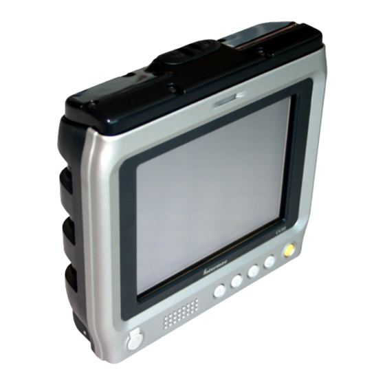
Fixed mount computer
Hide thumbs
Also See for CV30:
- User manual (118 pages) ,
- Installation manual (20 pages) ,
- Quick start manual (2 pages)
Table of Contents
Advertisement
Quick Links
Advertisement
Table of Contents

Related Manuals for Intermec CV30


Summary of Contents for Intermec CV30
- Page 1 Service Manual CV30 Fixed Mount Computer...
- Page 2 The information contained herein is provided solely for the purpose of allowing customers to operate and service Intermec-manufactured equipment and is not to be released, reproduced, or used for any other purpose without written permission of Intermec Technologies Corporation.
-
Page 3: Table Of Contents
Reflashing the CV30 ........... . . 28 Reflashing the CV30 Using an SD Card....... . 29 Reflashing the CV30 Using SmartSystems Server . - Page 4 CV30 Connectors........
-
Page 5: Before You Begin
Safety Summary Your safety is extremely important. Read and follow all warnings and cautions in this document before handling and operating Intermec equipment. You can be seriously injured, and equipment and data can be damaged if you do not follow the safety warnings and cautions. -
Page 6: Erste Hilfe
Safety Information Your safety is extremely important. Read and follow all warnings and cautions in this document before handling and operating Intermec equipment. You can be seriously injured, and equipment and data can be damaged if you do not follow the safety warnings and cautions. -
Page 7: Global Services And Support
Global Services and Support Warranty Information To understand the warranty for your Intermec product, visit the Intermec web site at www.intermec.com click Service & Support > Warranty. Disclaimer of warranties: The sample code included in this document is presented for reference only. -
Page 8: Who Should Read This Manual
Contact. Who Should Read This Manual This manual contains all of the information necessary to repair the CV30 Fixed Mount Computer. It provides an exploded view of the computer, the spare parts lists, procedures that describe how to replace parts, and information on how to test and reflash the computer. -
Page 9: Replacing Parts
Replacing Parts Use this chapter to learn how to open, replace parts in, and close the CV30 Fixed Mount Computer. This chapter also provides cautions to follow when servicing the CV30. CV30 Fixed Mount Computer Service Manual... -
Page 10: Cautions
Replacing Parts Use this section to understand how to replace the spared parts on the CV30. Each procedure lists the tools and parts you need to complete replacing the part. Opening the Top Cover (Radome) To open the top cover, you need these parts and tools. - Page 11 Vorsicht: Nicht am Antennenkabel ziehen, da das Kabel reißen könnte. Falls kein Antennenkabel-Ausbauwerkzeug verfügbar ist, einen Fingernagel unter den Sockel des Antennenkabels stecken und sacht anheben. 4 Completely separate the top cover from the CV30. Screw (6 places) cover Antenna...
-
Page 12: Opening The Front Cover
Screw (2 places) 3 Turn the CV30 over and lift the front cover away from the top of the CV30 being careful not to disconnect the keypad flex cable. Gently lay the front cover down with the flex cable connecting the two pieces. -
Page 13: Replacing The Radome (Top Cover)
Chapter 1 — Replacing Parts Replacing the Radome (Top Cover) There are two spared parts on the CV30 radome or top cover. You can replace the entire top cover assembly or you can just replace the radome daughter board PCB. To replace the top cover or the radome PCB, you need these parts and tools. -
Page 14: Replacing The Radome Board Assembly Pcb
2 Disconnect the two 802.11 radio antenna coaxial cables from the radome board assembly PCB. 3 Remove the five 4-40 x 1/4 inch Phillips screws that attach the radome board assembly PCB to the CV30 frame. CV30 Fixed Mount Computer Service Manual... - Page 15 (5 places) Coaxial cables Radome PCB 4 Lift the radome board assembly PCB away from the CV30 carefully and disconnect the CV30 radome harness. You will also need to carefully feed the 802.11 radio antenna coaxial cables through the radome board assembly PCB.
- Page 16 Backup battery b Insert the new backup battery and attach the cable to the Main PCB. 7 Attach the CV30 radome harness to the new radome board assembly PCB and feed the two 802.11 radio antenna coaxial cable connectors through the holes in the new radome board assembly PCB.
-
Page 17: Replacing The Touch Panel Assembly
Steckverbinder müssen vorsichtig geöffnet und geschlossen werden, damit sie nicht beschädigt werden. Beim Öffnen und Schließen keinen starken Druck auf den beweglichen Teil des Steckverbinders ausüben. 4 Lift the touch panel assembly away from the CV30. CV30 Fixed Mount Computer Service Manual... -
Page 18: Replacing The Display Frame Assembly
9 Replace the top cover and secure it with the six 4-40 x 3/8 inch Phillips screws removed previously and tighten to .62 Nm (5.5 lb-in). 10 Reconnect power to the CV30. Replacing the Display Frame Assembly To replace the display frame assembly, you need these parts and tools. - Page 19 Beim Öffnen und Schließen keinen starken Druck auf den beweglichen Teil des Steckverbinders ausüben. 4 Lift the touch panel assembly away from the CV30. 5 Remove the four 4-40 x 3/8 inch Phillips screws that attach the display frame to the CV30 base.
- Page 20 Chapter 1 — Replacing Parts Screw (4 places) Display frame assembly 6 Lift the display frame assembly away from the CV30 base and disconnect the display flex cable and the inverter PCB harness. Display frame assembly Inverter harness Flex cable 7 Insert the new display frame assembly and connect the display flex cable and the inverter PCB harness.
-
Page 21: Replacing The Inverter Board
3 Use the flathead screwdriver to release the two flex connectors that connect the touch panel to the CV30. The flex connectors are called zero insertion force (ZIF) connectors and they are very fragile. To avoid breaking the connectors, open and close them carefully. - Page 22 CV30 base. Screw (4 places) Display frame assembly 6 Lift the display frame assembly away from the CV30 base and disconnect the display flex cable and the inverter PCB harness. CV30 Fixed Mount Computer Service Manual...
- Page 23 8 Remove the two Phillips screws that attach the inverter board PCB to the frame display assembly, disconnect the display harness and the inverter harness from the inverter board PCB, and lift the inverter board PCB away from the frame display assembly. CV30 Fixed Mount Computer Service Manual...
- Page 24 10 Reattach the inverter PCB harness and the display harness to the inverter board PCB. 11 Insert the frame display assembly back into the CV30 base, connect the display flex cable and the inverter PCB harness, and replace the four 4- 40 x 3/8 inch Phillips screws removed in Step 5.
-
Page 25: Replacing The Keypad
5 Remove the yellow Kapton tape that covers the back of the speaker and disconnect the two cables from the keypad PCB. 6 Remove the five Phillips screws that secure the keypad PCB to the front cover and remove it. CV30 Fixed Mount Computer Service Manual... - Page 26 Keypad tape PCB cables Keypad PCB 7 If you need to replace the CV30 keypad, use the flathead screwdriver to pry the keypad away from the front cover until you can peel it off. Keypad assembly 8 Peel the backing off the new keypad assembly and firmly press it into place.
-
Page 27: Replacing The Touch Heater Pcb
14 Replace the top cover and secure it with the six 4-40 x 3/8 inch Phillips screws removed previously and tighten to .62 Nm (5.5 lb-in). 15 Reconnect power to the CV30. Replacing the Touch Heater PCB To replace the touch heater PCB, you need these parts and tools. - Page 28 Display frame assembly 5 Lift the display frame and touch panel assembly away from the CV30 base assembly. 6 Disconnect the touch heater PCB harness from the main PCB. 7 Remove the two 4-40 x 1/4 inch Phillips screws that secure the touch heater PCB to the base assembly and remove it.
-
Page 29: Replacing The Main Pcb
Druck auf den beweglichen Teil des Steckverbinders ausüben. 4 Remove the four 4-40 x 3/8 inch Phillips screws that attach the display frame to the CV30 base and lift them away from the base assembly. CV30 Fixed Mount Computer Service Manual... - Page 30 Touch heater PCB harness I/O PCB harness Power Backup connection battery cable cable 6 Remove the seven 4-40 x 1/4 inch Phillips screws that secure the main PCB to the base assembly and remove it. CV30 Fixed Mount Computer Service Manual...
- Page 31 PCB. 13 Replace the top cover and secure it with the six 4-40 x 3/8 inch Phillips screws removed previously and tighten to .62 Nm (5.5 lb-in). 14 Reconnect power to the CV30. CV30 Fixed Mount Computer Service Manual...
-
Page 32: Replacing The Gasket
Druck auf den beweglichen Teil des Steckverbinders ausüben. 4 Using your fingers, lift up on one corner of the gasket and pull up until the gasket is completely separated from the base assembly. CV30 Fixed Mount Computer Service Manual... - Page 33 Chapter 1 — Replacing Parts Gasket 5 Place the new gasket on the CV30 base assembly and starting at one corner, gently press the gasket onto the base assembly until the gasket is firmly attached. 6 Reconnect the keypad flex connector to the touch panel assembly.
-
Page 34: Replacing The Membrane Vent
2 Insert the new membrane vent and use the socket wrench to tighten it. Testing the CV30 With the Test Fixture After you replace any part of the CV30, you should use the test fixture to make sure that the CV30 is operating properly. To test the CV30, you need: •... - Page 35 Here is a list of the hardware you need to use the test fixture: • A PC or laptop • An Ethernet switch or hub • An access point • A CV30 developer cable assembly (P/N VE011-2018) • Three CAT5 cables • A CV30 • A custom serial null modem cable...
-
Page 36: Reflashing The Cv30
There are two ways to reflash the CV30: • You can reflash the CV30 using an SD card. For help, see the next section, “Reflashing the CV30 Using an SD Card.” CV30 Fixed Mount Computer Service Manual... -
Page 37: Reflashing The Cv30 Using An Sd Card
4 Copy all files in this directory to the SD card. Do not copy the .exe file to the SD card. 5 If you are using an SD card reader, remove the SD card from the CV30 and place it in the reader. -
Page 38: Reflashing The Cv30 Using Smartsystems Server
Chapter 1 — Replacing Parts 7 If you are using an SD card reader, insert the SD card into the CV30. Note: Make sure the CV30 has completely loaded all of the upgrade files before you remove the SD card or reset the computer. -
Page 39: Clean Booting The Cv30
To clean boot the CV30 1 Using a small pointed device (such as the end of the stylus) or your finger, press the Reset switch on the top of the CV30 at the same time as you press the Power button. - Page 40 Chapter 1 — Replacing Parts Reset The blue light on the CV30 blinks once and the CV30 starts the booting sequence. 2 Reload any custom applications and reset the time and date. CV30 Fixed Mount Computer Service Manual...
-
Page 41: Spare Parts List And Exploded Views
Spare Parts List and Exploded Views This chapter provides the exploded views and spare parts list for the CV30. CV30 Fixed Mount Computer Service Manual... -
Page 42: Cv30 Exploded Views And Parts Lists
Chapter 2 — Spare Parts List and Exploded Views CV30 Exploded Views and Parts Lists This chapter contains exploded views for the CV30. The exploded views have been broken down into these four parts: • Radome assembly exploded view • Touch panel and display exploded view •... - Page 43 CV30 radome service assembly VE011-S6015-xx CV30 radome daughter board PCB VE011-6011-xx Coaxial 90 mm cable VE011-8050-xx Coaxial 52 mm cable VE011-8051-xx CV30 radome board service assembly PCB VE011-S6026-xx DRCB-M1 116 module radio 855-064-001 CV30 radome PCB harness VE011-8054-xx Battery assembly VE011-S6027-xx...
-
Page 44: Touch Panel And Display Exploded View And Parts List
Chapter 2 — Spare Parts List and Exploded Views Touch Panel and Display Exploded View and Parts List Screw (5 places) Screw (4 places) Screw (2 places) Touch Panel and Display Exploded View CV30 Fixed Mount Computer Service Manual... - Page 45 CV30 keypad board PCB VE011-S6005-xx CV30 keypad PCB flex cable VE011-8052-xx Touch panel service assembly VE011-S6018-xx Frame display assembly VE011-S6019-xx Inverter board service PCB VE011-6006-xx CV30 inverter PCB harness VE011-8057-xx Cable display harness VE011-8053-xx CV30 Fixed Mount Computer Service Manual...
-
Page 46: Base I/O Assembly Exploded View And Parts List
Chapter 2 — Spare Parts List and Exploded Views Base I/O Assembly Exploded View and Parts List Screw (7 places) Screw (2 places) Screw (6 places) Base I/O Assembly Exploded View CV30 Fixed Mount Computer Service Manual... - Page 47 VE011-8053-xx CV30 touch heater PCB harness VE011-8055-xx CV30 I/O PCB harness VE011-8056-xx CV30 main PCB VE011-S6001-xx Housing rear gasket VE011-8056-xx CV30 touch heater board PCB VE011-S6004-xx Base I/O service assembly VE011-S6022-xx Membrane vent VE011-5006-xx CV30 Fixed Mount Computer Service Manual...
-
Page 48: Safety And Compliance Labels Exploded View And Parts List
Safety and Compliance Labels Spare Parts List Callout Description Part Number Safety and Compliance print-on-demand (POD) VE011-8092-xx blank label Safety and Compliance print-on-demand (POD) VE011-8044-xx protective cover I/O identification label VE011-8090-xx COA WinMobile 2005, V5.0 label 471-004-141 CV30 Fixed Mount Computer Service Manual... -
Page 49: Theory Of Operation
Theory of Operation This chapter provides the theory of operation for the CV30. CV30 Fixed Mount Computer Service Manual... -
Page 50: Product Architecture
V E011-8059-A0 Block Diagram Showing the Interconnection of the CV30 Boards The CV30 display is a module-based 6.4 inch diagonal color, transmissive, TFT LCD unit. It has a resolution of 480 x 640 pixels (VGA), each capable of 65,536 colors (16 bit RGB). It is backlit by cold cathode fluorescent lamps (CCFL). -
Page 51: Touch Panel And Touch Heater
• Two RS-232 serial COM ports with 2 D-Sub 9-pin male connectors. The TI MAX3243 transceiver chip is used for these two serial COM circuits. • A single D-Sub 15-pin male connector customized for the connection of two USB hosts and a USB client. CV30 Fixed Mount Computer Service Manual... -
Page 52: Inverter Board
Ethernet interface to the CV30. The magnetic portion of the circuit is placed here. The CV30 I/O board is connected to the MLB via the 50P wire harness connection. All differential signals were wired in twisted paired manner. Inverter Board The inverter board functions as the backlight source to power up the CCFL of the LCD Module. -
Page 53: Design Description
Chapter 3 — Theory of Operation Design Description The CV30 computer was designed to maximize data integrity in a mobile environment, regardless of external user control. The detailed descriptions of the block design are separated into power block, battery charging, system function, audio system, and communication system. -
Page 54: Internal Power System
Chapter 3 — Theory of Operation Internal Power System The CV30 power system consists of several bucks and boost converters, power switches, and miscellaneous circuitry that orchestrate the power subsystem. The main processor and PIC continuously monitor and control various aspects of the power subsystem when operating. - Page 55 DSUB_PW R_EN V5P0_USB1 POW ER DISTRIBUTION M IC2026 V5P0_USB2 nUSB_PSW 1 nUSB_PSW 2 OFF During Deep Sleep OFF During Sleep and Deep Sleep V5P0_USBH ISP1520 Always ON plane USBH_PW R_EN V5PO_MAIN Power Distribution System CV30 Fixed Mount Computer Service Manual...
-
Page 56: Heater Power System
The heater power system refers to the touch panel heater power. The purpose of the heater is to reduce the condensation and frost on the external surface of the display as a result of moving to and from sub- freezing temperatures to more temperate locations. CV30 Fixed Mount Computer Service Manual... -
Page 57: Logic Power System
This V12P0 will remain ON if an external power source is attached. V12P0_CCFL V12P0 To V12P0_CCFL CV30 Fixed Mount Computer Service Manual... -
Page 58: V5P0_Com1 And V5P0_Com2
V5P0_COM1 and V5P0_COM2 V5P0_MAIN To V5P0_COM1 and V5P0_COM2 Both the V5P0_COM1 and V5P0_COM2 are output from the V5P0_MAIN through the two individual fixed current limit power distribution switches MIC2015. The two switches are controlled by signal CV30 Fixed Mount Computer Service Manual... - Page 59 MAIN_PWR if the external power source is removed. The voltage range is defined between maximum of 4.2 V at full charge to minimum of 3.0 V at end of charge. VCC_CORE, VCC_PLL, VCC_SRAM, V2P5, V1P8 MAIN_PWR To VCC_CORE, VCC_PLL, VCC_SRAM, V2P5, V1P8 CV30 Fixed Mount Computer Service Manual...
- Page 60 MAIN_PWR to V3P3_MAIN. This supply feeds directly to the supply voltage of the DiskOnChip. V3P3_PIC V3P3_MAIN To V3P3_PIC The V3P3_PIC supplies power to the PIC controller. PIC18LF4320 is a ferrite filtered version of V3P3_MAIN. V3P3_CODEC_ANLG, V3P3_CODEC_DIG, V3P3_ANT_ANLG V3P3_MAIN To V3P3_CODEC_ANLG, V3P3_CODEC_DIG, V3P3_ANT_ANLG CV30 Fixed Mount Computer Service Manual...
- Page 61 This signal is asserted with the condition of both the ETH_PWR_EN and nBATT_FAULT_DET at Logic H. The CPU asserts the ETH_PWR_EN, unless the nBATT_FAULT_DET reveals the presence of the external power supply to the unit. V3P3_CF V3P3_AUX To V3P3_CF CV30 Fixed Mount Computer Service Manual...
-
Page 62: Backup Power System
72 hours. If external power is restored, the CV30 will resume the state it was in when power was removed. There is an internal protection circuitry within the battery pack to protect the battery from: •... -
Page 63: Power State Table
4 Idle. In this state the processor is powered and the internal clock is running but it is not executing any code. The SDRAM may be in auto power down mode. All the power planes are ON with the presence of the external power source. CV30 Fixed Mount Computer Service Manual... - Page 64 V1P8 Always ON plane V1P8_CPU, V1P8_CPU_MEM, V1P8_GF_HOST V1P5_LCD LCD_CORE_PWR_EN V3P3_MAIN, V3P3_PIC Always ON plane V3P3_CPU V3P3_CODEC_DIG, V3P3_CODEC_ANLG V3P3_ANT_ANLG nPWR_EN V3P3_SD nSD_PWR_EN V3P3_AUX nSYS_EN V3P3_ETH, V3P3_ETH_ANLG nETH_PWR_EN_PF V3P3_CF nCF_PWR_EN_PF V3P3_BT nBT_PWR_EN_PF V3P3_TXCVR nCF_PWR_EN_PF and nETH_EN CV30 Fixed Mount Computer Service Manual...
-
Page 65: Detection Circuit
Power Routing Circuit Several power routing circuits are implemented to allow portions of the CV30 to be powered ON or OFF under software control as needed. These parts that can be powered ON or OFF include: • LCD •... -
Page 66: System Function
CODEC is ON, controlled by signal AUDIO_CODEC_PWR_EN. Microchip PIC Controller The Microchip PIC controller has several housekeeping tasks in the CV30: • External power source detect • Cold / Warm RESET • Status LED control •... - Page 67 Status LED Control The status lights on the CV30 turn on to indicate the status of the network connection, a successful decode of a bar code, or a user-defined function. The status indicators are comprised of green, amber, and blue LEDs. The blue LED is controlled by the PIC, while the main processor controls the green and amber LEDs.
- Page 68 Chapter 3 — Theory of Operation • Blue LED (Ready-to-Work indicator). The blue light indicates when the CV30 is ready to use in your application, typically TE 2000. The Ready-to-Work indicator has three states: • Off: The TE 2000 application has not loaded successfully, or you are not running a Ready-to-Work application.
-
Page 69: Audio System
CV30. The system software determines the functionality of the CV30 based on the configuration information. This EEPROM is non-volatile so this vital information is never lost. It is very... - Page 70 (such as MP3 decoded file) is sent over this link. AC97 CODEC The CODEC is comprised of the following functions: • Stereo A2D converters with variable rate sampling. • Stereo D2A converters with variable sample rate play. CV30 Fixed Mount Computer Service Manual...
- Page 71 The CODEC has a touch panel controller built in. In order to use the controller to operate the touch panel, power to the TPVDD needs to be supplied. However this part of controller was not used in the CV30. A separate LDO is provided to power the loud speaker amplifier TPA2005 from the V5P0_MAIN.
-
Page 72: Mlb Processor Functions
MLB Processor Functions The terminal has an Intel X-scale processor that runs the Windows Mobile OS. The main engineering goals of the CV30 are to provide power management and option flexibility while maintaining open system standards. The CV30 can accommodate different modules and internal radios including 802.11b/g and Bluetooth. - Page 73 RTC via a software utility. The external RTC chip provides an accurate 32 KHz clock for the main processors internal RTC to use. The CV30 uses the Epson RTC-8564NB(LF).
- Page 74 The protocol looks for collisions and retries if they are detected. The main processor sends commands to the PIC controller to execute and the PIC sends results or responses back to the main processor over this bus. CV30 Fixed Mount Computer Service Manual...
- Page 75 USB hosts. This signal pair from the processor is differential. Both 1.5 and 12 Mbps operation is supported. Signal Description USBH_P0 USB data line positive USBH_N0 USB data line negative CV30 Fixed Mount Computer Service Manual...
- Page 76 Direction COM2_DCD Data Carrier Detect Input COM2_DSR Data Set Ready Input COM2_DTR Data Terminal Ready Output COM2_CTS Clear to Send Input COM2_RTS Request to Send Output COM2_RXD Received Data Input COM2_TXD Transmitted Data Output CV30 Fixed Mount Computer Service Manual...
- Page 77 SD slot. This is a method that the service center can use to reprogram the CV30 bootloader into flash if it becomes corrupted. Normally, the flash can be upgraded using the bootloader software.
-
Page 78: Main Bus Device
Power to this memory is provided continuously to prevent loss of programs or data. There are two SRAM with a combined capacity of 64 The performance for the mobile SDRAM parts is: • CL=2 @ 83 MHz or CL=3 @ 133 MHz CV30 Fixed Mount Computer Service Manual... -
Page 79: Ethernet Controller
Both the isolation transformer and the standard RJ45 connector reside on the I/O board. The transmit and receive signals are routed through an internal wire harness from the MLB board to the I/O board. Both the transmit and receive signal lines are differential pairs. CV30 Fixed Mount Computer Service Manual... - Page 80 D1-D15, 16-bit data bus. Bi-direction ETH_RESET Controller reset Input Asynchronous ready Output ETH_IRQ INTRO, interrupt to the processor Ouput nETH_IORD nRD, read strobe Input nETH_IOWR nWR, write strobe Input nETH_BE [1:0] nByte enable Input Ethernet Controller Diagram CV30 Fixed Mount Computer Service Manual...
-
Page 81: Usb Hub
The hub is protected by the external over-current switch MIC2026, which is connected through the digital over current signal nUSBOC1/2 to the hub. The protection can be configured as individual port control or ganged-port control depending on the pin PSWn_N configuration. CV30 Fixed Mount Computer Service Manual... -
Page 82: Cv30 Connectors
Chapter 3 — Theory of Operation CV30 Connectors The CV30 contains numerous internal connectors and external peripheral connectors. These connections allow for maximum flexibility in the configuration of the system. Internal Connectors The internal connectors provide board-to-board interfaces and interfaces to other devices. - Page 83 • D-Sub 15-pin: 2 USB Host and 1 USB Client (Kycon K66X-E15P-N) Pin Number Signal USBC_5V_DET USBC_N USBC_P FRAME GND USBH_DM1 USBH_DP1 V5P0_USB1 FRAME GND V5P0_USB2 USBH_DM2 USBH_DP2 FRAME GND • RJ45 8-pin Ethernet connector (Kycon GWX-S-88-50) Pin Number Signal CV30 Fixed Mount Computer Service Manual...
-
Page 84: Clock Map
All data line signals that enter or exit the terminal are ESD and EMI protected to prevent damage to the terminal and to meet agency requirements. Clock Map Use the following clock block diagram to understand the all clock frequency used by the CV30 system. 13 Mhz 104 Mhz CONTROLLER SDRAM 3.8MHZ... - Page 86 Worldwide Headquarters 6001 36th Avenue West Everett, Washington 98203 U.S.A. tel 425.348.2600 fax 425.355.9551 www.intermec.com CV30 Fixed Mount Computer Service Manual *939-003-001* P/N 939-003-001...
Need help?
Do you have a question about the CV30 and is the answer not in the manual?
Questions and answers