
Subscribe to Our Youtube Channel
Related Manuals for Clarke ETC400


Summary of Contents for Clarke ETC400
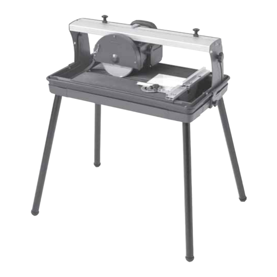
- Page 1 600W ELECTRIC TILE CUTTER 600W ELECTRIC TILE CUTTER MODEL No: ETC400 Part No: 3400748 OPERATION & MAINTENANCE INSTRUCTIONS 0706...
-
Page 2: Specifications
Please note that the details and specifications contained herein, are correct at the time of going to print. However, CLARKE International reserve the right to change specifications at any time without prior notice. Waste electrical products should not be disposed of with general household waste. Please dispose... -
Page 3: Table Of Contents
Thank you for purchasing this CLARKE Tile Cutter designed for DIY and light commercial use for cutting all types of ceramic tiles.. Before attempting to use the cutter, please read this manual thoroughly and follow the instructions carefully. In doing so you will ensure the safety of yourself and that of others around you, and you can look forward to the equipment giving you long and satisfactory service. -
Page 4: Safety Precautions
SAFETY PRECAUTIONS WARNING: As with all machinery, there are certain hazards involved with their operation and use. Exercising respect and caution will considerably lessen the risk of personal injury. However, if normal safety precautions are overlooked or ignored, personal injury to the operator or damage to property, may result. ALWAYS Learn the machines applications, limitations and the specific potential hazards peculiar to it. -
Page 5: Electrical Connections
ELECTRICAL CONNECTIONS Connect the mains lead to a standard, 230 Volt (50Hz) electrical supply through an approved 13 amp BS 1363 plug, or a suitably fused isolator switch. WARNING! THIS APPLIANCE MUST BE EARTHED IMPORTANT: The wires in the mains lead are coloured in accordance with the following code: Green &... -
Page 6: Check List
Before attempting to assemble and use the tiling cutter, carefully unpack and lay out the contents on a clean surface. Check for missing/damaged parts. If any shortages or damage is found, please notify your Clarke dealer where the cutter was purchased ASAP, alternatively telephone Clarke International on 020-8988-7400. CONTENTS Note: Item Nos in brackets refer to parts diagram on page •... -
Page 7: Assembly
ASSEMBLY cont. 6. Install the pump by clipping into position as shown in Fig. 3, ensure the pump tubing is not kinked. Fig. 3 7. Once the pump is clipped firmly into position, carefully lower the cutter assembly into position in the water tank taking care not to trap the pump tubing or pump power lead. -
Page 8: Operation
11. Two Head Transverse Stops are provided on Fig. 7 the top of the machine. These allow head movement to be restricted, as desired. Thread the slides on to the screw threads of the transverse stops, ensurintg they are the right way up, then screw on the stop knobs as shown in Fig.7 Fig. -
Page 9: Maintenance
DO NOT force the head. Maintain the maximum disc speed at all times, allow the tool to do the work. Always cut in a straight line and DO NOT attempt to cut a curved line. Keep hands well clear of the disk whilst it is in motion. Remove all pieces using a scrap piece of wood, or similar, before making the next cut. -
Page 10: Parts Diagram
PARTS DIAGRAM -10-... -
Page 11: Parts List
PARTS LIST No. Part No Description Qty No. Part No Description HTETC40001 Knob HTETC40042 Screw M6x16 HTETC40002 Locating Block (A) HTETC40043 Motor HTETC40003 Locating Block (B) HTETC40044 Power Cord HTETC40004 Hex Bolt M6x20 HTETC40045 Slide Block HTETC40005 Guide Ruler HTETC40046 Mitre Gauge HTETC40006 Guide Bar...
Need help?
Do you have a question about the ETC400 and is the answer not in the manual?
Questions and answers