
Subscribe to Our Youtube Channel
Related Manuals for Clarke CAT127


Summary of Contents for Clarke CAT127
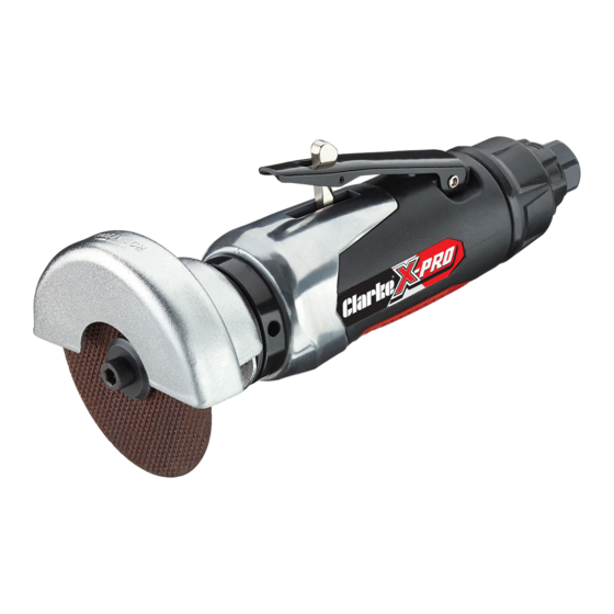
- Page 1 CUT-OFF TOOL MODEL NO: CAT127 PART NO: 3120141 OPERATING & MAINTENANCE INSTRUCTIONS GC0414...
- Page 2 Your tool has been designed to give long and trouble free service. If, however, having followed the instructions in this booklet carefully, you encounter problems, take the unit to your local CLARKE dealer. IMPORTANT Please read all of the safety and operating instructions carefully before using this product.
-
Page 3: General Safety Rules
GENERAL SAFETY RULES CAUTION: FAILURE TO FOLLOW THESE PRECAUTIONS COULD RESULT IN PERSONAL INJURY, AND/OR DAMAGE TO PROPERTY. WORK ENVIRONMENT 1. Keep the work area clean and tidy. 2. Dress appropriately - Do not wear loose clothing or jewellery. Tie long hair out of the way. -
Page 4: Use Of Cutting Discs
• The tool will be left unattended. • Moving to another work area. • Passing the tool to another person. 14. Never use the tool if it is defective or operating abnormally. 15. The tool should be serviced at regular intervals by qualified service personnel. - Page 5 OVERVIEW When opening the carton for the first time, check against the following list that all the items are present. Any damage or deficiency should be reported to your CLARKE dealer immediately. NO DESCRIPTION NO DESCRIPTION Disc Retaining Washer Air Inlet...
-
Page 6: Compressed Air Requirements
COMPRESSED AIR REQUIREMENTS WARNING: COMPRESSED AIR CAN BE DANGEROUS. ENSURE THAT YOU ARE FAMILIAR WITH ALL PRECAUTIONS RELATING TO THE USE OF COMPRESSORS AND COMPRESSED AIR SUPPLY. • Use only clean, dry, regulated compressed air as a power source. • Air compressors used with the tool must comply with the appropriate European Community Safety Directives. -
Page 7: Before Use
6. Your air tool is now ready for use. You can fit a whip hose with a quick fit coupling if required (available from your Clarke dealer). Parts & Service: 020 8988 7400 / E-mail: Parts@clarkeinternational.com or Service@clarkeinternational.com... -
Page 8: Installing The Cutting Disc
CLARKE replacement parts may result in safety hazards, decreased tool performance and may invalidate your warranty. • Replacement cutting discs are available from your Clarke dealer. (Part number 3110731). ADJUSTING THE SPEED 1. Set the tool speed by rotating the control to one of the four settings. -
Page 9: Setting The Air Exhaust Deflector
3. Too much pressure can cause the disc to break and may shorten the life of the tool. 4. Release the trigger to stop the tool. • The tool will continue to rotate for a short time after the trigger has been released. -
Page 10: Troubleshooting
2. Motor parts worn. 2. Return to Clarke dealer for repair. 3. Worn or sticking 3. Drip air tool lubricating mechanism due to oil into air inlet. Allow oil lack of lubricant. -
Page 11: Maintenance
1. Before use, drain water from the air tank, air line and compressor. 2. Pour a few drops of CLARKE airline oil, into the air inlet. This should be carried out regardless of whether or not an in-line mini oiler is used. If an in- line mini oiler is not used, this procedure should be repeated after every two to three hours of use. -
Page 12: Specifications
If the tool is to be stored, or is idle for longer than 24 hours, run a few drops of Clarke air line oil into the air inlet, and run the tool for 5 seconds in order to lubricate the internal parts. -
Page 13: Parts List And Diagram
PARTS LIST & DIAGRAM Parts & Service: 020 8988 7400 / E-mail: Parts@clarkeinternational.com or Service@clarkeinternational.com... - Page 14 PARTS LIST & DIAGRAM Description No Description Main Housing Gasket Valve Bushing Bushing Trigger Bearing Trigger Pin Rear Motor Plate Locking Lever Spring Rotor Rotor Blade O-Ring Cylinder Exhaust Deflector Washer O-Ring Front Plate Air Regulator Bearing Set Plate Drive Shaft O-Ring O-Ring Set Plate...
-
Page 15: Declaration Of Conformity
DECLARATION OF CONFORMITY Parts & Service: 020 8988 7400 / E-mail: Parts@clarkeinternational.com or Service@clarkeinternational.com...
Need help?
Do you have a question about the CAT127 and is the answer not in the manual?
Questions and answers