Table of Contents
Advertisement
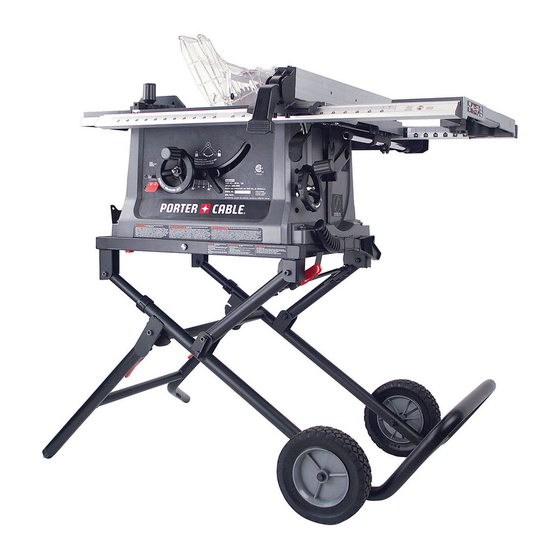
10 IN. (254 MM)
JOBSITE TABLE SAW
SCIE CIRCULAIRE DE 254 MM
(10 PO) SUR LE LIEU DE TRAVAIL
SIERRA DE MESA DE 254 MM
(10 PULG.) PARA LA OBRA
Instruction Manual
Manuel d'instructions
Manual de instrucciones
www.portercable.com
INSTRUCTIVO DE OPERACIÓN, CENTROS DE
SERVICIO Y PÓLIZA DE GARANTÍA.
CATALOG NUMBER
ADVERTENCIA: LÉASE ESTE INSTRUCTIVO
ANTES DE USAR EL PRODUCTO.
PCB220TS
1
Advertisement
Table of Contents

Related Manuals for Porter-Cable 10 IN. (254 MM) JOBSITE TABLE SAW


Summary of Contents for Porter-Cable 10 IN. (254 MM) JOBSITE TABLE SAW
- Page 1 10 IN. (254 MM) JOBSITE TABLE SAW SCIE CIRCULAIRE DE 254 MM (10 PO) SUR LE LIEU DE TRAVAIL SIERRA DE MESA DE 254 MM (10 PULG.) PARA LA OBRA Instruction Manual Manuel d’instructions Manual de instrucciones www.portercable.com INSTRUCTIVO DE OPERACIÓN, CENTROS DE SERVICIO Y PÓLIZA DE GARANTÍA.
-
Page 2: Table Of Contents
TABLE OF CONTENTS SECTION PAGE PRODUCT SPECIFICATIONS........................CALIFORNIA PROPOSITION 65......................... SAFETY GUIDELINES - DEFINITIONS ...................... POWER TOOL SAFETY ..........................TABLE SAW SAFETY ..........................ELECTRICAL REQUIREMENTS AND SAFE- TY................... TOOLS NEEDED FOR ASSEMBLY......................CARTON CONTENTS..........................KNOW YOUR JOBSITE TABLE SAW......................GLOSSARY OF TERMS..........................ASSEMBLY AND ADJUSTMENTS...................... -
Page 3: California Proposition 65
CALIFORNIA PROPOSITION 65 WARNING Some dust created by power sanding, sawing, grinding, drilling and other construction activities contains chemicals known to the state of California to cause cancer, birth defects or other reproductive harm. Some examples of these chemicals are: Lead from lead-based paints, Crystalline silica from bricks and cement and other masonry products, and Arsenic and chromium from chemically-treated lumber. -
Page 4: Power Tool Safety
POWER TOOL SAFETY (not glasses) that comply with ANSI Safety standard GENERAL SAFETY INSTRUCTIONS Z87.1. Everyday eyeglasses have only impact– BEFORE USING THIS POWER TOOL resistant lenses. They ARE NOT safety glasses. Safety is a combination of common sense, staying alert NOTE: Glasses or goggles not in compliance with and knowing how to use your power tool. - Page 5 TABLE SAW SAFETY 1. ALWAYS USE SAW BLADE GUARD, riving knife 14. AVOID AWKWARD OPERATIONS and hand and anti-kickback pawls for every through–sawing positions where a sudden slip could cause your hand to move into the saw blade. operation. Through–sawing operations are those in which the blade cuts completely through the 15.
- Page 6 TABLE SAW SAFETY KICKBACKS SAW BLADE GUARD ASSEMBLY, ANTI-KICKBACK ASSEMBLY AND RIVING KNIFE KICKBACKS: Kickbacks can cause serious injury. A kickback occurs when a part of the workpiece binds Your table saw is equipped with a blade guard assembly, between the saw blade and the rip fence, or other fixed anti-kickback assembly and riving knife that covers the object, and rises from the table and is thrown toward the blade and reduces the possibility of accidental blade...
-
Page 7: Electrical Requirements And Safety
ELECTRICAL REQUIREMENTS AND SAFETY POWER SUPPLY AND MOTOR SPECIFICATIONS Use a separate electrical circuit for your tool. This circuit must not be less than #14 wire and should be protected WARNING with a 15 Amp time delay fuse. Before connecting the motor to the power line, make sure the switch is in the To avoid electrical hazards, fire hazards, or damage off position and the electric current is rated the same as... - Page 8 The adapter (Fig. 2) has a rigid lug extending from it that MUST be connected to a permanent earth ground, such as a properly grounded receptacle box. CAUTION In all cases, make certain the receptacle is properly grounded. If you are not sure, have a qualified electrician check the receptacle.
-
Page 9: Tools Needed For Assembly
TOOLS NEEDED FOR ASSEMBLY CARTON CONTENTS UNPACKING AND CHECKING CONTENTS Supplied Not Supplied Carefully unpack the table saw and all its parts, and compare against the list below and the illustration on the Flat bladed screwdriver Blade wrench next page. With the help of an assistant place the saw on a secure surface and examine it carefully. - Page 10 UNPACKING YOUR JOBSITE TABLE SAW...
-
Page 11: Know Your Jobsite Table Saw
KNOW YOUR JOBSITE TABLE SAW Table insert Table Side table extension Overload protection Blade guard storage Blade/blade wrench storage Blade tilting handwheel ON/OFF switch with key Push stick Blade elevation handwheel Blade bevel lock handle Stand Riving knife Blade guard Anti-kickback pawl Rip fence Miter gauge... -
Page 12: Glossary Of Terms
GLOSSARY OF TERMS ANTI-KICKBACK PAWLS – Prevents the workpiece NON-THROUGH SAWING - refers to any cut that does from being kicked upward or back toward the front of the not completely cut through the workpiece. table saw by the spinning blade. OVERLOAD RESET SWITCH –... -
Page 13: Assembly And Adjustments
ASSEMBLY AND ADJUSTMENTS Estimated Assembly Time: 45 - 60 Minutes. Fig. B right side WARNING For your safety, never connect plug to power source receptacle until all assembly and adjustment steps are complete, and you have read and understood the safety instructions. ASSEMBLING THE STAND (FIG. - Page 14 FOLDING THE STAND (FIG. B, C, F) 1. Raise the cover plate (4) on the right side of stand, Fig. G pull the locking handle (5) out, and then move the saw close to the wheel (6). (Fig. C, F) 2.
- Page 15 Push stick (Fig. J) A storage bracket for the push stick (1) is located on the 1. Insert the riving knife between the set plate (4) and retaining clip (7). right side of the stand (2). Store the push stick (3) as 2.
- Page 16 INSTALLING THE BLADE TILTING HANDWHEEL 5. Snap two short plastic stops (7) over the end of the rear table extension tubes (2). Make sure the locating (FIG. O) pin in the location seats fit into the matching holes in 1. Bag " A " Attach the blade tilting handwheel (1) to the extension tubes.
- Page 17 ADJUSTING THE 90° AND 45° POSITIVE STOPS 6. Thread the arbor nut (2) onto the arbor, making sure the flat side of the nut is against the blade, then (FIG. U, V) hand-tighten. (Fig. T) Your saw has positive stops that will quickly position the 7.
- Page 18 5. Adjust the collar (5) so it contacts the bracket (3) 7. Rotate the blade bringing the marked tooth to the when the blade is 45° to the table. Tighten the two rear and about 1/2 in. (12.7 mm) above the table. set screws.
- Page 19 INSTALLING THE RIVING KNIFE (FIG. Y) 1. Remove the table insert and raise the blade to the maximum height by turning the blade elevation 1. Remove the table insert. handwheel clockwise. 2. With the blade elevation handwheel, raise the blade 2.
- Page 20 Fig. AA Fig. BB Loosen NOTE: Fig. CC • This table saw is provided with a 10 in. diameter blade with a body thickness of 1.8 mm (0.07 in.) thick Tighten with a kerf of 2.6 mm (0.10 in.). The riving knife is 2.2 mm (0.09 in.) thick.
- Page 21 Removing the blade guard and anti-kickback pawl square to the miter gauge bar by using a combination assembly (Fig. CC, DD) square. WARNING MITER GAUGE OPERATION (FIG. GG) To avoid injury from an accidental start, make sure The miter gauge is accurately constructed with index the switch is in the OFF position and the plug is stops at 0º, 15º, 30º, 45º, 60º...
- Page 22 Fig. JJ 4. If adjustment is needed to make the fence parallel to the groove, do the following: • Loosen the two screws (3) and lift up on the handle (2). • Hold the fence bracket (4) firmly against the front of the saw table.
-
Page 23: Operation
OPERATION BASIC SAW OPERATIONS Fig. NN RAISE THE BLADE (FIG. MM) To raise or lower the blade, turn the blade elevation handwheel (1) to the desired blade height, and then tighten the bevel lock handle (2) to maintain the desired blade angle. - Page 24 Fig. PP 1. Remove the miter gauge and store it in the “storage” rear scale compartment in the base of the saw. 2. Secure the rip fence to the table. 3. Raise the blade so it is about 1/8 in. higher than the top of the workpiece.
- Page 25 MAKE A FEATHERBOARD (FIG. SS) 8. Continue pushing the workpiece (6) with the push stick (3-Fig. QQ) or push block until it passes through Select a solid piece of lumber approximately 3/4 in. (19 the blade guard and clears the rear of the table. mm) thick, 4 in.
- Page 26 Fig. VV WARNING Make sure the screw heads do not stick out from the bottom of the base, they must be flush or recessed. The bottom must be flat and smooth enough to rest on the saw table without rocking. Fig.
- Page 27 Fig. WW Fig. YY USING THE WOOD FACING ON THE MITER GAUGE (FIG. XX) COMPOUND MITER CROSSCUTTING (FIG. ZZ) Slots are provided in the miter gauge for attaching an 0°~45° BLADE BEVEL & 0°~45° MITER ANGLE auxiliary facing (1) to make it easier to cut very long or short pieces.
- Page 28 Fig. aa 4. Mount the auxiliary fence (4) with C-clamps. 5. Use the push block (2) to move the workpiece. NOTE: Mount the featherboard to table as shown, so the leading edges of featherboard will help workpiece complete cutting. Fig. cc USING THE WOOD FACING ON THE RIP FENCE (FIG.
- Page 29 6. Use only the correct number of round outside blades and inside chippers as shown in the dado set’s instruction manual. Blade or chipper must not exceed 1/2 inch (12.7 mm). 7. Check saw to ensure that the dado will not strike the housing, insert, or motor when in operation.
-
Page 30: Maintenance
MAINTENANCE MAINTAINING YOUR TABLE SAW LUBRICATION Ball bearings in the table saw are packed with grease at GENERAL MAINTENANCE the factory and require no further lubrication. WARNING REPLACING THE CARBON BRUSHES (FIG. ff) ALWAYS use safety glasses. Everyday eyeglasses WARNING are NOT safety glasses. -
Page 31: Troubleshooting Guide
Use only identical replacement parts. For a parts list or to order parts, visit our service website at www.portercable. com. You can also order parts from your nearest Porter-Cable Factory Service Center or Porter-Cable Authorized Warranty Service Center. Or, you can call our Customer Care Center at (888) 609-9779. - Page 32 1. Miter gauge out of adjustment. 1. Adjust miter gauge. accurate 45° and 90° crosscuts. For assistance with your product, visit our website at www.portercable.com for a list of service centers, or call the Porter-Cable Customer Care Center at (888) 609-9779.
-
Page 33: Accessories And Attachments
To avoid the risk of personal injury: To reduce the risk of injury, only Porter-Cable • Do not use a dado with a diameter larger than 6 in. recommended accessories should be used with this (152.4 mm). -
Page 34: Push Stick Pattern
PUSH STICK PATTERN PUSH STICK CONSTRUCTION • Use good quality plywood or solid wood • Use 1/2 in. (13 mm) or 3/4 in. (19 mm) material • Push stick MUST be thinner than the width of material being cut Drill Hole for Hanging Notch for Prevent Hand from Slipping... -
Page 35: Parts List
PARTS LIST 10 IN. (254 MM) JOBSITE TABLE SAW PARTS LIST FOR JOBSITE TABLE SAW I.D. Description Size Qty I.D. Description Size Qty I.D. Description Size 08VH CORD CLAMP 0KF6 CR. RE. PAN HD. SCREW M4*0.7-8 2T6D ANIT-KICKBACK PAWL ASS’Y... - Page 36 10 IN. (254 MM) JOBSITE TABLE SAW SCHEMATIC FOR JOBSITE TABLE SAW 2T6D 2TUY 2X69 2V3E 0K4T 0J5A 2V3F 2WW9 2WVT 0KQW 2Z08 2Z2M 2WVX 29R9 0K6U 0K72 2RXQ 10K5 2WVS 28BN 2CFE 2YBD 2UZU 0KCZ 0KSM 2RVE 0T01 0KBA...
- Page 37 10 IN. (254 MM) JOBSITE TABLE SAW PARTS LIST & SCHEMATIC FOR STAND I.D. Description Size I.D. Description Size 2149 KNOB 2WR8 SUPPORTING TUBE ASS’Y 2888 CAP HD. SQ.NECK BOLT M8*1.25-50 2WR9 CONNECTOR TUBE ASS’Y 090Q PLUNGER HOUSING 2WRA SUPPORTING TUBE ASS’Y...
- Page 38 10 IN. (254 MM) JOBSITE TABLE SAW PARTS LIST & SCHEMATIC FOR MOTOR I.D. Description Size I.D. Description Size 0HV3 BALL BEARING 2RPS MOTOR COVER 0HX9 NEEDLE BEARING 2RPY SPACER 0JEB C-RING 2RPZ HELIX GEAR 0JG7 PARALLEL KEY 2RQ0 CUTTER SHAFT 0JX3 HEX.
- Page 39 NOTES...
-
Page 40: Warranty
In addition to the warranty, PORTER-CABLE tools are covered by our: 1 YEAR FREE SERVICE: PORTER-CABLE will maintain the tool and replace worn parts caused by normal use, for free, any time during the first year after purchase.
Need help?
Do you have a question about the 10 IN. (254 MM) JOBSITE TABLE SAW and is the answer not in the manual?
Questions and answers
i have pcb220ts S/N 143732 the blade will not rase or lower what should i do?
If the blade on a Porter-Cable PCB220TS Jobsite Table Saw will not raise or lower, brush or blow out loose dust and dirt from the elevation and tilting mechanisms.
This answer is automatically generated
The mechanism which raises and lowers the blade binds up badly when I try to raise the blade, but does not do that when I lower the blade.
The blade raising mechanism on the Porter-Cable 10 IN. Jobsite Table Saw could be binding due to sawdust and dirt in the elevation or tilting mechanisms. Cleaning out loose dust and dirt may resolve the issue.
This answer is automatically generated