
Related Manuals for SPORTS ART 6310


Summary of Contents for SPORTS ART 6310
- Page 1 U.S.A. PDF created with FinePrint pdfFactory Pro trial version http://www.pdffactory.com...
-
Page 2: Table Of Contents
Installation Requirements..................List of parts......................3. Treadmill Assembly....................Step by Step Instructions..................For long handrail assembly................. For medical handrail assembly................4. How To Use Your 6310 Treadmill................ 5. 6310 Electronic Software..................Basic Operation....................Quick Start......................Display Window Functions.................. Programmable Functions.................. -
Page 3: Introduction
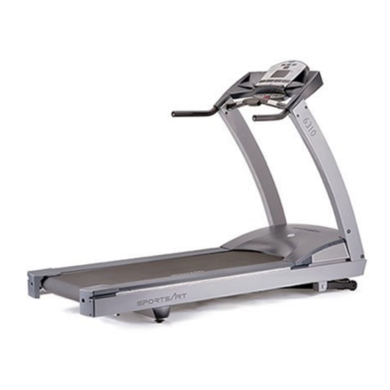
INTRODUCTION Congratulations on purchasing one of the finest piece of commercial exercise equipment on the market today, the SportsArt 6310 Commercial Treadmill. The 6310 is designed with the end user in mind and constructed of high quality materials and designed for years of trouble-free use. -
Page 4: Safety Precautions
PDF created with pdfFactory trial version www.pdffactory.com... - Page 5 PDF created with pdfFactory trial version www.pdffactory.com...
-
Page 6: Assembling Your Treadmill
ASSEMBLING YOUR TREADMILL Installation Requirements Thank you for purchasing our product. Even though we go to great efforts to ensure the quality of each product, occasional errors and/or omissions do occur. In any event should you find the product to be defective or missing a part, please contact your dealer. -
Page 7: Treadmill Assembly
TREADMILL ASSEMBLY Step by Step Instructions When you remove the treadmill from its box, first check to make sure all of the parts are present. Then, read through the assembly instructions before you begin. 1. Tip the treadmill on its side. Make sure the running belt is in position in the tracks of the Belt Alignment Guides on the underside of the machine. - Page 8 3. Rotate display to fixed position as figure below, attach all side fasteners to position without fully tightened. (See Fig. 3) FIG.3 4. Insert short handrail into Handrail Bracket, then secure 6 screws provided and fully tightened all side fasteners. (See Fig.4) FIG.4 PDF created with pdfFactory trial version www.pdffactory.com...
- Page 9 5. Press life post's shroud into respective poeition. (See Fig. 5) FIG.5 6. Insert upright post screw caps into proper position. (See Fig.6) FIG.6 PDF created with pdfFactory trial version www.pdffactory.com...
-
Page 10: For Long Handrail Assembly
7. Connect power cable as indicated in Fig.7, and fasten it. FIG.7 For long handrail assembly: 4. For long handrail assembly. Insert long handrail into handlebar bracket, then secure the fasteners provided and fully tightened all side fasteners. (See Fig.6) FIG.4-1 PDF created with pdfFactory trial version www.pdffactory.com... - Page 11 5. Press upright post's enclosure into respective position. (See Fig.5-1) FIG.5-1 6. Insert upright post screw caps into proper position. (See Fig.6-1) FIG.6-1 PDF created with pdfFactory trial version www.pdffactory.com...
-
Page 12: For Medical Handrail Assembly
7. Connect power cable as indicated in Fig.7-1, and fasten it. FIG.7-1 For medical handrail assembly: 4. Insert medical handrail into the upper handrail bracket. Attach screws to position without fully tightening. Install medical handrail post and tighten all screws. (See Fig.4-2) FIG.4-2 PDF created with pdfFactory trial version... - Page 13 5. Press upright post's enclosure into keyed position. (See Fig.5-2) Press down FIG.5-2 6. Insert upright post screw caps into proper position. (See Fig.6-2) FIG.6-2 PDF created with pdfFactory trial version www.pdffactory.com...
-
Page 14: How To Use Your 6310 Treadmill
HOW TO USE YOUR 6310 TREADMILL: 1. Basic operation: A. To start using the treadmill: 1. Press any key. 2. Enter AGE (AGE LED will light up), press INCLINE up, down button to select age and then press ENTER. 3. Enter WEIGHT (WEIGHT LED will light up), press INCLINE up, down button to set WEIGHT, and then press ENTER. - Page 15 5. Display functions: DISTANCE : Displays total miles or kilometers. CALORIES : Total accumulated calories burned. TIME : Displays total time accumulated or time remaining in a preprogrammed course. SPEED : Press these keys to adjust your desired speed. The speed range for the treadmill is from 0.1-12mph (0.2-20kph).
-
Page 16: Electronic Software
6310 Electronic Software A. Basic operation Turn on the power. You will see the below SPORTSART scroll message. Please follow the below steps. SPORTSART 6310 1. Press any button to begin. 2. Enter your age ( the corresponding LED will be lit ), The age default is 35, Press ▲▼... -
Page 17: Quick Start
(3) When the time is not set at "0", (the minimum time will be 10 minutes, and the maximum time will be 99 minutes) than the manual mode and other programmed courses will be counting down. The message will show as below ▲▼... -
Page 18: Programmable Functions
(3) Display total accumulated distance on the treadmill. (4) Display the total accumulated time on the treadmill. To access these settings and information, while the banner "SPORTSART 6310" is scrolling on the display, press and hold the CHANGE button for 3 seconds. The software will prompt you through these features. - Page 19 2. The HRC mode will allow you to modify the HRC target heart rate (YES or NO). ▲▼ PRESS TO SELECT MODIFT HRC TARGET HR (Y/N)?, PRESS ENTER ▲▼ Press to select modify HRC target HR. Then press ENTER for YES or Number YES: Follow display prompts.
-
Page 20: Button Functions
E. Button functions ▲▼ SPEED: 1. Press to increase and decrease the belt speed. 2. The speed range is from 0.1mph to 12mph; 0.2kph to 20kph. 3. At any time you can push SPEED up button for QUICK START. ▲▼ INCLINE: 1. -
Page 21: Course Description
F. Course Description The dot matrix display is a 3 color display. Red represents portions of the program that has been completed. Orange represents your position within the program. Green represents the portion of the course to come. 1. Manual: Manual is the default program for QUICK START. Press SPEED up to begin. - Page 22 6. Interval Courses The interval course are each based on "work" and "rest" periods. Each is defined by speed and incline and can be set at any time. Each period is remembered by the last portion of each period. For example, in the "work" period the moment before it changes to the "rest"...
-
Page 23: Hrc
" to input your age, then press "ENTER." 2. Selection of MODIFY HRC TARGET HR (Y/N) When the starting display shows "SPORTS ART", hold "CHANGE" key for 3 seconds to get to selection of MPH/KPH, then press "ENTER". The display will ▲▼... - Page 24 Display appears like this when you select No ▲▼ PRESS TO SELECT MODIFY HRC TARGET HR (Y/N)?, PRESS ENTER Display appears like this when you select YES. ▲▼ PRESS TO SELECT MODIFY HRC TARGET HR (Y/N)?, PRESS ENTER The 4 scenarios are as the following: Scenario 1: When you have input your correct age at the beginning, and select NO for the MODIFY HRC TARGET HR.
-
Page 25: Hrc Control Procedures
▲▼ PRESS TO INPUT YOUR AGE, PRESS ENTER AGE 35 ▲▼ Step 3: Please use the to set your age, then press "ENTER". ▲▼ Step 4: The display will appear "PRESS TO MODIFY YOUR HEART RATE LIMIT, PRESS ENTER". ▲▼ Step 5: Using to set your desired Heart Rate, then press "ENTER". - Page 26 NO HEARTRATE READING, PLEASE CHECK TRANSMITTER 3. When machine is receiving signal from your polar transmitter normally, the display will appear message as the below image. The 114 in the below image is an example of heart rate ratio. ▲ PRESS SPEED A.
- Page 27 5. When the treadmill does not detect your heart rate signal, the dot matrix LED will show the message as below. If no signal is detected for more than 30 seconds, the treadmill will stop automatically, and return to MANUAL mode. NO HEARTRATE READING, PLEASE CHECK TRANSMITTER 6.
-
Page 28: Guidelines For Exercise
GUIDELINES FOR EXERCISE How hard should I exercise? Studies show that to achieve the benefits of aerobic exercise, it is necessary to work within your training zone. Your training zone depends on your age and level of fitness. The above chart indicates the recommended Heart Rate training zones (darkened area of the chart). -
Page 29: Adjusting The Running Belt
ADJUSTING THE RUNNING BELT The 6310 treadmill includes a belt alignment gauge located on the left side of the motor enclosure. The edge of the running belt should be in the middle of the green portion of the gauge. If the belt edge is in the green area, the belt is properly adjusted. - Page 30 5. If the belt is in the left red zone: Using the hex Allen wrench, turn the left belt adjustment bolt, located at the rear of the treadmill, clockwise 1/4 turn at a time, Then turn the right belt adjustment bolt counter-clockwise 1/4 turn. Let the treadmill run 30 seconds.
- Page 31 11. If the belt is too loose, you can tighten the belt by equally adjusting both rear roller bolts clockwise 1/2 turn at a time. Conversely, if the belt is too tight, adjust both rear roller bolts counterclockwise 1/2 turn at a time (see Fig.7-3). Fig.7-3 Periodically monitor the position of the belt to ensure peak performance CAUTION:...
-
Page 32: Floor Level Adjustment
FLOOR LEVEL ADJUSTMENT If the treadmill is unsteady on your floor, turn the floor level adjustment on the rear feet of the treadmill. Raise or lower the floor level adjustment to steady your treadmill (see Fig.8) Fig.8 PDF created with pdfFactory trial version www.pdffactory.com... -
Page 33: Troubleshooting
TROUBLE SHOOTING Service Required When Service Required LED lights up, It will scroll the message of "Service Required treadmill shutting down stopping" in the electronic display. Then the treadmill stops running automatically and shows up the accumulative distance data in the 7-segment display. Please contact your dealer for more information. Error messages 1. -
Page 34: Main Fuse Failure
Main Fuse Failure If nothing is displayed on the electronics display, please check the POWER switch located on the front of the treadmill. If it is ON, then the fuse may be damaged and must be replaced. CAUTION: MAKE SURE THE TREADMILL POWER PLUG IS REMOVED FROM OUTLET BEFORE REPLACING THE FUSE. -
Page 35: Electronic Wiring Schematic
Wiring Schematic: Your Authorized Distributor PDF created with pdfFactory trial version www.pdffactory.com...
Need help?
Do you have a question about the 6310 and is the answer not in the manual?
Questions and answers