Table of Contents
Advertisement
Quick Links
Sports Art Industrial Co., Ltd. (Headquarter)
Sports Art America Inc.
#11, Gong Huan Road,
19510 144th Ave. N.E., Suite A-1,
Tainan City, Taiwan
Woodinville, WA 98072
T: 886 6 3840888
T: +1 425 4819479
F: 886 6 3840999
F: +1 425 4888155
info@sportsart.com.tw
info@gosportsart.com
Sports Art Europe, Middle East & Africa
Sports Art China
Strada Cantonale 42, Ch-6534 San Vittore,
Room 2202, BLDG. A, Huapu Garden,
Switzerland
Dongzhimen South Street, No. 9,
T: +41 91 8273908
Dongcheng District Beijing, 100007 China
F: +41 91 8273910
T: +86 10 84094122/84094123
giorgio365@ticino.com
F: +86 10 84094121
ISO 9001/14001 Certified
GoSportsArt.com
Sports Art Fitness UK Ltd.
Unit 2, 3 Charnwood Business Park,
North Road, Loughborough,
LE11 1LE, England
T: +44 1509 274440
ukinfo@gosportsart.com
USA
2016.05
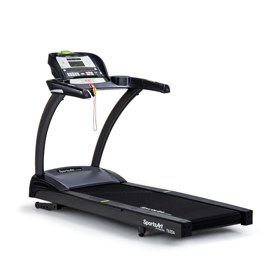
T635A LED Treadmill
Owner's Manual
Advertisement
Table of Contents

Related Manuals for SPORTS ART T635A


Summary of Contents for SPORTS ART T635A
- Page 1 F: 886 6 3840999 F: +1 425 4888155 T: +44 1509 274440 info@sportsart.com.tw info@gosportsart.com ukinfo@gosportsart.com Sports Art Europe, Middle East & Africa Sports Art China Strada Cantonale 42, Ch-6534 San Vittore, Room 2202, BLDG. A, Huapu Garden, Switzerland Dongzhimen South Street, No. 9,...
-
Page 2: Table Of Contents
STEP 5 Align the Walk Belt ..............25 STEP 6 Adjust the Walk Belt Tension ............ 26 STEP 7 Install the Power Cord .............. 27 5. UNDERSTAND THE T635A LED DISPLAY ........28 DISPLAY Overview ................28 DISPLAY Specifications ................ 29 DISPLAY Windows ................ -
Page 3: Introduction
1. INTRODUCTION Congratulations on the purchase of a high quality SportsArt product, the T635A treadmill. Constructed of high quality materials and designed for years of reliable performance, this product was made for full commercial use. Before this product is assembled or operated, we recommend that you familiarize yourself with this manual. -
Page 4: Safety Precautions
2. SAfETy PRECAUTIONS This product was designed and built for optimum safety. However certain precau- tions apply during the use of this product. Please note the following safety precautions: • Please read the entire manual before assembly and operation. Make sure the product is installed and operated as instructed in this manual. - Page 5 2. SAfETy PRECAUTIONS (CONTINUED) CAUTION: If you feel any pain or any abnormal sensations, STOP YOUR WORKOUT and consult your physician immediately. Work within your recommended exercise level. DO NOT work to exhaustion. Before beginning any exercise program, you should consult with your doctor. It is recommended that you undergo a complete physical examination.
- Page 6 2. SAfETy PRECAUTIONS (CONTINUED) If you are a French speaking person in North America, please place the sticker contained in the owner’s manual on the product as shown. Custom- ers in other areas will not receive the sticker.
- Page 7 2. CONSIGNES DE SÉCURITÉ IMPORTANTES Votre tapis de course SportsArt a été conçu et fabriqué afin d’assurer une sécurité optimale. Cependant certaines précautions s’appliquent chaque fois que vous uti- lisez votre tapis de course. • Lisez entièrement le manuel avant l’assemblage et l’utilisation. Veuillez aussi noter les consignes de sécurité...
- Page 8 2. CONSIGNES DE SÉCURITÉ (SUITE) • Pour éviter de vous blesser, restez sur les bandes de repos (barres latérales) avant de démarrer le tapis de course. • Ce tapis de course n’est pas destiné à être utilisé par des personnes (y com- pris des enfants) dont les capacités physiques, sensorielles ou mentales sont réduites ou qui ne disposent pas de l’expérience ou du savoir nécessaires, sauf si celles-ci ont au préalable été...
-
Page 9: List Of Parts
3. LIST Of PARTS Assembly Parts Name Qty. No. Name Qty. A1 Display A6b Motor left cover A2 Handlebar assembly A7 Left pedestal A3 Right pedestal A8 Owner’s manual A4 Feeder cord A9 Hardware kit A5 Waterproof ring A10 Power cord A6 Main frame A11 French Sticker (For USA) A6a Motor right cover... - Page 10 3. LIST Of PARTS (CONTINUED) Components on the Product Name Specification Notes Inner hex screw M8*L20 Spring washer Serrated washer D18*d8.5*t2 Mushroom top inner hex screw M8*L20 Serrated washer (curved) D18*d8.5*t2 Mushroom top inner hex screw M8*L20 Serrated washer D18*d8.5*t2 Mushroom top inner hex screw M5*L12 Phillips screw...
-
Page 11: Assemble The Product
4. ASSEMBLE THE PRODUCT Follow instructions below to assemble this product. Note that in this manual the words “left” and “right” are used to refer to the product and its parts. As such, these designations correspond to the “left” and “right” sides of a person in position to exercise on this product. -
Page 12: Step 0 Preparation: Inspect The Walk Belt Placement
STEP 0 Preparation: Inspect Walk Belt Placement Inspect the position of the walk belt in relation to the guide rollers. The walk belt should be in the groove of the guide rollers (image √). Make sure that the walk belt is not outside of the groove of the guide rollers (image X). If the walk belt is in the wrong position, press the walk belt into the groove of the guide rollers. -
Page 13: Step 1 Install The Pedestals And Handlebar Assembly
STEP 1 Install the Pedestals and Handlebar Assembly Follow instructions below to install the pedestals and handlebar assembly. The illustration below provides an overview of this step. - Page 14 STEP 1 Install the Pedestals and Handlebar Assy. (Cont.) (a) First, remove screws (41) from pedestal mounts. (b) Next, inspect the spring clip (A) and screw socket (B) to see if they are in place still. If not, get them from the hardware kit and inset them in place.
- Page 15 STEP 1 Install the Pedestals and Handlebar Assy. (Cont.) Follow instructions (a) through (d) below to thread the data cable through the right pedestal. Before assembly, make sure the left & right pedestals are align with left and right sides on the main frame. (a) Pull the cable from the right side of pedestal mount.
- Page 16 STEP 1 Install the Pedestals and Handlebar Assy. (Cont.) Hold the data cable at the top of the right pedestal (A3), and insert the bot- tom of the right pedestal (A3) onto the pedestal mount. Place the water guard (A5) on the pedestal higher than the motor cover. Repeat the process for the left pedestal (A7) assembly.
- Page 17 STEP 1 Install the Pedestals and Handlebar Assy. (Cont.) Follow the instructions (a) through (f) to finish installing handlebar assembly. (a) Remove screws (42) (43) from the mounting plates on the bottom of the handlebar assembly (A2). (b) Place the left side of handlebar assembly (A2) into left pedestal (A7). (c) Securely connect the cables from the right pedestals (A3) at area A to the cables of the handlebar assembly (A2) as shown.
- Page 18 STEP 1 Install the Pedestals and Handlebar Assy. (Cont.) (d) Place the right side of handlebar assembly (A2) into right pedestal (A3). Make sure the cable is not shown or pinched. (e) Put the previously removed screws (42) (43) back into the pedestals. Tighten the screws (42) at B area first, then tighten the screws (43) at C area next.
- Page 19 STEP 1 Install the Pedestals and Handlebar Assy. (Cont.) After securing the handlebar assembly, secure screws onto the base of left and right pedestals at area A. Put motor right and left side covers (A6a) (A6b) into place, and secure them with screws (33) and then slide the water guard (A5) downward into place against the motor cover.
-
Page 20: Step 2 Install The Display
STEP 2 Install the Display Follow instructions below to install the display onto the cowling. The illustration below provides an overview of this step. - Page 21 STEP 2 Install the Display (Continued) Please follow steps (a) through (f) to install the display. (a) First, remove screws (44) from the display mount on the handlebar assembly (A2). (b) Place the display (A1) onto the handlebar assembly (A2) Note: make sure the display is aligning with its guiding pieces to avoid damaging the control board.
- Page 22 STEP 2 Install the Display (Continued) (d) Connect cables in areas A & B. (e) After securing cable connections, arrange all the cables nicely, Afterwards push the display (A1) slightly upward, aligning it correctly, then press it into place on the handlebar assembly. Note: make sure the cables are not pinched.
- Page 23 STEP 2 Install the Display (Continued) (g) Hold the display (A1) forward slightly as shown and then press downward when securing screws (44). (h) Finally, use screws (47) to secure the rear cover (46) back into place.
-
Page 24: Step 3 Move The Treadmill Into Place For Use
STEP 3 Move the Treadmill into Place for Use Put the hands underneath the read end of treadmill shown in area A; grasp the treadmill then lift it up, and roll the treadmill into the desired place. -
Page 25: Step 4 Level The Treadmill
STEP 4 Level the Treadmill Press downward on the rear part of the treadmill as shown. Inspect whether the treadmill rests flat on the floor. If the treadmill wobbles, adjust treadmill levelers as follows: (a) Loosen the leveler nut. (b) Rotate the leveler foot downward, touching the floor. (c) Rotate the leveler nut upward, against the frame of the product, to secure this position. -
Page 26: Step 5 Align The Walk Belt
STEP 5 Align the Walk Belt (a) First, make sure the treadmill is on a leveled surface and the incline is at (b) Start the speed at a lower rate of 3kph/2.5mph to check if the walk belt is aligned and there is an equal amount of space between walk belt and side-rails on both sides. -
Page 27: Step 6 Adjust The Walk Belt Tension
STEP 6 Adjust the Walk Belt Tension Walk belt tension is important to treadmill performance. As your foot hits the walk belt, does the walk belt stop sluggishly before regaining traction? Or, if you stomp your feet, bracing against the direction of rotation, does the walk belt not pause whatsoever? When either of these two conditions occurs, walk belt tension should be adjusted. -
Page 28: Step 7 Install The Power Cord
STEP 7 Install the Power Cord (a) First remove screws (45) from the power cord socket on the product. (b) Insert the power cord into place on the product. (c) Secure the power cord (A10) connector screws (45). And insert the other end of the power cord into the power socket on the wall. -
Page 29: Understand The T635A Led Display
5. UNDERSTAND THE T635A LED DISPLAy DISPLAy Overview The T635A display was designed to help people obtain their fitness goals simply and conveniently. Please familiarize yourself with the features of this display and thereby get optimum benefit and enjoyment from this product. -
Page 30: Display Specifications
DISPLAy Specifications ● Speed: 0.5 to 20.0 kph; 0.3 to 12.0 mph ● Incline: 0% to 15%, in increments of 0.5% ● Time: 0:00 - 300:00 ● Distance: 0.00 - 9999 km or mile ● Calories: 0 - 9999 kcal ●... - Page 31 DISPLAy Keys (Continued) RANDOM – Press this key to select one of an almost endless number of randomly generated workout programs. Each key press, the console will randomly generate a different program. INTERVAL – Press this key to select one of three interval programs: 1:1, 1:2, 2:2. Numbers represent minutes.
-
Page 32: Display Safety Key
DISPLAy Keys (Continued) VOLUME + / - – iPod, iPhone analog audio volume adjustment. (Note: this is an option feature and it is only compatible with Apple 30 pin connector.) MYE wireless TV audio channel receivers volume adjustment. (MyE Wireless TV Audio_ Channel Receivers and module not provided.) CHANNEL ▲/▼... -
Page 33: Operate The Product
6. OPERATE THE T635A LED TREADMILL OPERATION Safety Operating Area (a) Safety clearance required as below shown. Do not allow people to be near this area when operating. (b) Make sure stand on the center of the running belt where are marked with green round labels at area E when operating. -
Page 34: Operation Proper Workout Position And Safety Get Off
OPERATION Proper Workout Position and Safety Get Off (a) User proper workout position as shown. (b) If the user needs to leave the working running belt urgently, please put the hands on the handlebars and feet step on the landing strips as below shown and then turn off the treadmill to get off the treadmill. -
Page 35: Operation Quick Start
OPERATION Quick Start There are two ways to start operating this product: (1) Press the QUICK START key, or (2) press the PROGRAM/GOAL SELECTION key to enter a preset program. Using the QUICK START key allows you to begin exercising immediately, without first entering user information. -
Page 36: Operation Display
OPERATION Start a Workout Program (Continued) ● The DISTANCE setting range is from 0.1 to 99.9 miles or kilometers, with a default value 2.0 miles (3.0 kilometers). If the program time limit is activated at the user preference setting, then the DISTANCE goal will be deactivated. -
Page 37: Operation Cool Down
OPERATION Cool Down Once the workout goal (time, distance, or calorie expenditure) has been ob- tained, the product will enter a two-minute cool down period. The display will count down from two to zero. When the countdown reaches zero, the cool down period will end. The mes- sage “REVIEW SUMMARY”... -
Page 38: Operation Workout Programs
OPERATION Workout Programs Workout program details are explained below. MANUAL This program allows you to manually control speed and incline. In manual mode, simply press SPEED ▲/▼ keys to control speed and INCLINE ▲/▼ keys to adjust incline. HILL There are three hill workouts, HILL 1, HILL 2, and HILL 3, each of which is represented by a different hill illustration. - Page 39 OPERATION Workout Programs (Continued) TRACK The track workout profile is designed with 400m (1/4 mile) track as the distance for each lap run. User may select either Time, Distance or Calories as the running goal. The TRACK 5K workout automatically has a goal of 5 kilometers. (If the time limit function is activated, the time limit will become the workout goal.) The TRACK 10K workout automatically has a goal of 10 kilometers.
- Page 40 OPERATION Workout Programs (Continued) WfI (Wellness fitness Initiative) When the WFI program is selected the message “WEAR HR STRAP” appears. When a heart rate signal is received, the display prompts users to input height. If 20 seconds pass without a heart rate signal, the message screen shows “NO HR SIGNAL, TEST REQUIRES HR”.
- Page 41 OPERATION Workout Programs (Continued) • Gender a. A gender prompt, M/F, will appear. b. Press SPEED ▲/▼ keys and INCLINE ▲/▼ keys to select your gender. c. Press the ENTER key to confirm the setting. At this point, Army and Marines fitness tests will begin.
- Page 42 OPERATION Workout Programs (Continued) • “1-WALK 2-RUN” will appear. a. To select the walking test, press the numeric 1 key or the ENTER key. Since the exerciser must wear a telemetry heart rate strap during these tests, the message window will show “WEAR HR STRAP”. If a heart rate signal is detected within 20 seconds, the fitness test pro gram will begin.
- Page 43 OPERATION Workout Programs (Continued) CARDIO & WT LOSS & ZONE TRAINER In heart rate control programs, speed or incline values automatically adjust to keep the exerciser’s pulse at the optimum rate to obtain his or her fitness goals. Target heart rate calculations are a percentage of a “maximum” heart rate based on age.
- Page 44 OPERATION Workout Programs (Continued) • INCLINE control mode If incline is your preferred heart rate control variable, the incline position will automatically change to maintain your target heart rate. You can also press INCLINE ▲/▼ keys to manually adjust the incline and speed value. Heart rate control programs require the use of a telemetry heart rate strap.
-
Page 45: Operation User Preferences And Component Versions
OPERATION User Preference and Component Versions User preference settings allow you to change default settings and review some historical data of this product. To access user preference settings, press the CHANGE DISPLAY key for 2 seconds during Banner page. ● Unit setting: the default unit is English. On the message window, “UNIT –... -
Page 46: Operation Error Messages
OPERATION Error Messages Error messages can appear on this treadmill as a troubleshooting aid. Error messages appear in the following format: “ERROR _X_Y”. X represents the category of the error. Y represents the specific issue. In the position of the X placeholder, the following numbers can appear to represent the category of the malfunction: Code Explanation... -
Page 47: About Heart Rate Detection
7. ABOUT HEART RATE DETECTION Heart rate detection functions are selected at the time of purchase. Not every product has every type of heart rate detection. The following explains factors that influence the performance of two of the most common types of heart rate detection devices. -
Page 48: Guidelines For Exercise
8. GUIDELINES fOR EXERCISE HOW HARD SHOULD I EXERCISE? Studies show that to benefit from aerobic exercise, people need to maintain a certain heart rate during their workouts. Your heart rate training zone depends on your age and fitness level. The darkened area in the chart to the right represents the recommended heart rate training zone for people of various ages. -
Page 49: Maintenance
9. MAINTENANCE This section covers maintenance topics, including instructions on replacing a fuse and lubricating the walk belt, along with the presentation of a main- tenance schedule, maintenance task list, one-year maintenance log, and electronics block diagram. MAINTENANCE Safety Precautions ●... -
Page 50: Maintenance Circuit Breaker
MAINTENANCE Circuit Breaker (a) A circuit breaker is an automatically operated electrical switch designed to protect an electrical circuit from damage caused by overcurrent/ overload or short circuit. A spring located under the push button causes the button at area D to lift up and the breaker to trip as shown. (b) After the fault is repaired by qualified technicians, press the push button to reset circuit breaker to resume normal operation. -
Page 51: Maintenance Lubrication System
MAINTENANCE Lubrication System Lubrication System flowchart Model No. Display ex: T655 Total Exercise 5 seconds Distance Display (km) Power On RESET Walks Belt Version Display Total Exercise Total Exercise Total Exercise Speed Total ex:T655 Distance Display (mile) Distance Display (km) Distance Display (km) Running Time... - Page 52 MAINTENANCE Lubrication System (Continued) To replace the lubricant bottle, follow instructions (a) through (d) below. (a) Loosen the screws on the bezel and push the bezel up. (b) Take the old lubricant bottle out. (c) Unscrew the nozzle from the old lubricant bottle and screw it onto new bottle.
- Page 53 MAINTENANCE Lubrication System (Continued) Error Messages: There are 2 error messages with this system. Error 1: It indicates that the system memory failing and it will not be able to perform any auto lubrication. Error 2: It indicates motor is failing or system will not be able to perform any function.
-
Page 54: Maintenance Schedule
MAINTENANCE Schedule Area Day Week Month Quarter Year Notes Exterior Clean. Screws Inspect and secure loose parts. Treadmill test Ensure the treadmill operates properly. Inspect alignment (centering) and look Walk belt for wear. Walk deck Inspect for wear. Belt guides Inspect for normal rotation. -
Page 55: Maintenance Task List
MAINTENANCE Task List Like cars, fitness products require maintenance. Regular maintenance ex- tends product life, and failure to maintain products can void the manufac- turer’s warranty. Copy the maintenance log sheet, and record maintenance work for each fitness product. Daily tasks 1. -
Page 56: Maintenance One-Year Maintenance Log
MAINTENANCE One-year Maintenance Log Facility:_______________________ Supervisor:____________________ Product model number:__________ Serial number:_________________ Start date: ____________________ End date:_____________________ Daily Tasks Weeks 1-7 Weeks 8-14 Weeks 15-21 Week 22-28 Completed Daily Tasks Week 29-35 Week 36-42 Week 43-49 Week 50-52 Completed Weekly Tasks Weeks 1-7 Weeks 8-14 Weeks 15-21 Weeks 22-28... -
Page 57: Accessories
10. ACCESSORIES There are accessories attached to this console; some are standard and some are optional. The following explains the details of each accessory and its function. USB CHARGER (Standard) The USB charger will provide 5V 500mA voltage for the smart phone or other devices charging. -
Page 58: Accessories Entertainment Cap
ACCESSORIES Entertainment Cap (a) RFID member card slot: work with both optional SA WELL+ and ECOFIT member cards. (Not available yet.) (b) Bluetooth/WIFI button: When a smart phone is connected with equipment, press this button to disconnect. Scan the QR code or touch the NFC tag on the console to connect to the equipment again if necessary. -
Page 59: Accessories Mye Wireless Tv Audio_Channel Receivers
ACCESSORIES MyE Wireless TV Audio_Channel Receivers If your equipment has been installed MYE Wireless TV Audio_Channel Receivers, the display must has Channel Keys. Please make sure your equipment is with the correct overlay as below. (a) None Treadmill (Bike, Elliptical and Stepper...etc.) Left display: Without Channel Keys. - Page 60 ACCESSORIES MyE Wireless TV Audio_Channel Receivers(Cont.) MyE Wireless TV Audio_Channel Receivers functions: 1. The receiver has two kinds of module as below. (Note: MyE Wireless TV Audio_Channel Receivers and Module not provided.) (1). MC3R-9(900MHZ) must work with MYE Wireless TV Audio_Channel Receivers MWTD-S9.
-
Page 61: Accessories Options
ACCESSORIES Options 1. Long Handrails 2. Fan Set 3. External Mount TV Bracket... -
Page 62: Appendixes
11. APPENDIXES APPENDIXES Electronics Block Diagram iPod Audio Board USB Board Head Phone Board Option SA WELL+ Connection key USB Board Continua Adapter Board Option CSAFE Board Numeric Key Board HTR Board Control Board HRC Board Contact HTR plates Bridge Board Fan Board Safety Key Board Option... - Page 63 your Authorized Distributor...
Need help?
Do you have a question about the T635A and is the answer not in the manual?
Questions and answers