Table of Contents
Advertisement
Advertisement
Table of Contents

Related Manuals for SPORTS ART T645L


Summary of Contents for SPORTS ART T645L
- Page 1 T645 LED Treadmill Owner’s Manual...
-
Page 2: Table Of Contents
T645 LED OWNER’S MANUAL CONTENTS 1. INTRODUCTION ................2 2. SAFETY PRECAUTIONS ..............3. LIST OF PARTS ................. 4. ASSEMBLE THE PRODUCT ............. STEP 0 Preparation: Inspect the Walk Belt Placement ......10 STEP 1 Install the Pedestals and Handlebar Assembly ......11 STEP 2 Install the Display .............. -
Page 3: Introduction
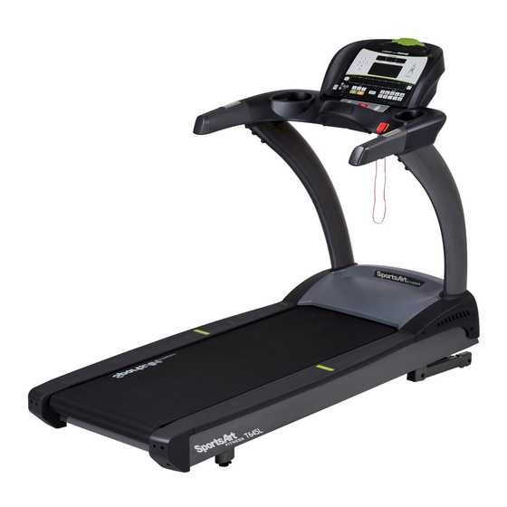
1. INTRODUCTION Congratulations on the purchase of a high quality SportsArt product, the T645 treadmill. Constructed of high quality materials and designed for years of reliable performance, this product was made for full commercial use. Before this product is assembled or operated, we recommend that you familiarize yourself with this manual. -
Page 4: Safety Precautions
2. SAfETy PRECAUTIONS This product was designed and built for optimum safety. However certain precau- tions apply during the use of this product. Please note the following safety precautions: • Please read the entire manual before assembly and operation. Make sure the product is installed and operated as instructed in this manual. - Page 5 2. SAfETy PRECAUTIONS (CONTINUED) CAUTION: If you feel any pain or any abnormal sensations, STOP YOUR WORKOUT and consult your physician immediately. Work within your recommended exercise level. DO NOT work to exhaustion. Before beginning any exercise program, you should consult with your doctor. It is recommended that you undergo a complete physical examination.
- Page 6 2. CONSIGNES DE SÉCURITÉ IMPORTANTES Votre tapis de course SportsArt a été conçu et fabriqué afin d’assurer une sécurité optimale. Cependant certaines précautions s’appliquent chaque fois que vous uti- lisez votre tapis de course. • Lisez entièrement le manuel avant l’assemblage et l’utilisation. Veuillez aussi noter les consignes de sécurité...
- Page 7 2. CONSIGNES DE SÉCURITÉ (SUITE) • Pour éviter de vous blesser, restez sur les bandes de repos (barres latérales) avant de démarrer le tapis de course. • Ce tapis de course n’est pas destiné à être utilisé par des personnes (y com- pris des enfants) dont les capacités physiques, sensorielles ou mentales sont réduites ou qui ne disposent pas de l’expérience ou du savoir nécessaires, sauf si celles-ci ont au préalable été...
-
Page 8: List Of Parts
3. LIST Of PARTS Assembly Parts Name Qty. No. Name Qty. A1 Display A6a Motor right cover A2 Handlebar assembly A6b Motor left cover A3 Right pedestal A7 Left pedestal A4 Feeder cord A8 Owner’s manual A5 Waterproof ring A9 Hardware kit A6 Main frame A10 Power cord... - Page 9 3. LIST Of PARTS (CONTINUED) Components on the Product Name Specification Notes Inner hex screw M8*L20 Spring washer Serrated washer D18*d8.5*t2 Mushroom top inner hex screw M8*L20 Serrated washer (curved) D18*d8.5*t2 Mushroom top inner hex screw M8*L20 Serrated washer D18*d8.5*t2 Mushroom top inner hex screw M5*L12 Phillips screw...
-
Page 10: Assemble The Product
4. ASSEMBLE THE PRODUCT Follow instructions below to assemble this product. Note that in this manual the words “left” and “right” are used to refer to the product and its parts. As such, these designations correspond to the “left” and “right” sides of a person in position to exercise on this product. -
Page 11: Step 0 Preparation: Inspect The Walk Belt Placement
STEP 0 Preparation: Inspect Walk Belt Placement Inspect the position of the walk belt in relation to the guide rollers. The walk belt should be in the groove of the guide rollers (image √). Make sure that the walk belt is not outside of the groove of the guide rollers (image X). If the walk belt is in the wrong position, press the walk belt into the groove of the guide rollers. -
Page 12: Step 1 Install The Pedestals And Handlebar Assembly
STEP 1 Install the Pedestals and Handlebar Assembly Follow instructions below to install the pedestals and handlebar assembly. The illustration below provides an overview of this step. (a) First, remove screws (41) from pedestal mounts. (b) Next, inspect the spring clip (A) and screw socket (B) to see if they are in place still. - Page 13 STEP 1 Install the Pedestals and Handlebar Assy (Cont.) Follow instructions (a through d) below to thread the data cable through the right pedestal. Before assembly, make sure the left & right pedestals are align with left and right sides on the main frame. (a) Pull the cable from the right side of pedestal mount.
- Page 14 STEP 1 Install the Pedestals and Handlebar Assy (Cont.) While holding the data cable to prevent it from slipping into the pedestal, lift the top of the right pedestal (A3). Then insert the pedestal base onto its mount. Use screws (41) to loosely secure the right pedestal (A3) into place. Repeat the process for the left pedestal assembly.
- Page 15 STEP 1 Install the Pedestals and Handlebar Assy (Cont.) Follow the instructions (a through f) to finish install handlebar assembly. (a) Remove screws (42, 43) from the mounting plates on the bottom of the handlebar assembly (A2). (b) Place the left side of handlebar assembly (A2) into left pedestal (A7). (c) Securely connect the right cables from the handlebar assembly (A2) to the right pedestals (A3) cables.
- Page 16 STEP 1 Install the Pedestals and Handlebar Assy (Cont.) (d) Place the right side of handlebar assembly (A2) into right pedestal (A3). Make sure the cable is not shown or pinched. (e) Put the previously removed screws (42, 43) back into the pedestals. Tighten the screws (42) at the B area first, then tighten the screws (43) at the C area next.
- Page 17 STEP 1 Install the Pedestals and Handlebar Assy (Cont.) After securing the handlebar assembly, secure screws onto the base of left and right pedestals (area A). Put motor right and left side covers (A6a, A6b) into place, and secure them with screws (33). Then slide the water guard (A5) downward into place against the motor cover.
-
Page 18: Step 2 Install The Display
STEP 2 Install the Display Follow instructions below to install the display onto the cowling. The illustration below provides an overview of this step. - Page 19 STEP 2 Install the Display (Continued) Please follow steps (a through f) to install the display. (a) First, remove screws (44) from the display mount on the handlebar assembly (A2). (b) Place the display (A1) onto the handlebar assembly (A2) Note: make sure the display is aligning with its guiding pieces to avoid damaging the control board.
- Page 20 STEP 2 Install the Display (Continued) (d) Connect cables in areas A & B. (e) After securing cable connections, arrange all the cables nicely, Afterwards push the display (A1) slightly upward, aligning it correctly, then press it into place on the handlebar assembly. Note: make sure the cables are not pinched.
-
Page 21: Step 3 Move The Treadmill Into Place For Use
STEP 3 Move the Treadmill into Place for Use Put the hands underneath the read end of treadmill shown in area A; grasp the treadmill then lift it up, and roll the treadmill into the desired place. -
Page 22: Step 4 Level The Treadmill
STEP 4 Level the Treadmill Press downward on the rear part of the treadmill as shown. Inspect whether the treadmill rests flat on the floor. If the treadmill wobbles, adjust treadmill levelers as follows: (a) Loosen the leveler nut. (b) Rotate the leveler foot downward, touching the floor. (c) Rotate the leveler nut upward, against the frame of the product, to secure this position. -
Page 23: Step 5 Align The Walk Belt
STEP 5 Align the Walk Belt (a) First, make sure the treadmill is on a leveled surface and the incline is at (b) Start the speed at a lower rate of 3kph/2.5mph to check if the walk belt is aligned and there is an equal amount of space between walk belt and side-rails on both sides. -
Page 24: Step 6 Adjust The Walk Belt Tension
STEP 6 Adjust Walk Belt Tension Walk belt tension is important to treadmill performance. As your foot hits the walk belt, does the walk belt stop sluggishly before regaining traction? Or, if you stomp your feet, bracing against the direction of rotation, does the walk belt not pause whatsoever? When either of these two conditions occurs, walk belt tension should be adjusted. -
Page 25: Step 7 Install The Power Cord
STEP 7 Install the Power Cord First remove screws (45) from the power cord socket on the product. Insert the power cord into place on the product. Secure the power cord (A10) connector screws (45). And insert the other end of the power cord into the power socket on the wall. -
Page 26: Understand The T645 Led Display
5. UNDERSTAND THE T645 LED DISPLAy DISPLAy Overview The T645 display was designed to help people obtain their fitness goals simply and conveniently. Please familiarize yourself with the features of this display and thereby get optimum benefit and enjoyment from this product. 1. -
Page 27: Display Specifications
DISPLAy Specifications ● Speed: 0.2 to 20.0 kph; 0.1 to 12.0 mph ● Incline: 0% to 15%, in increments of 0.5% ● Time: 0:00 - 300:00 ● Distance: 0.00 - 9999 km or mile ● Calories: 0 - 9999 kcal ●... - Page 28 DISPLAy Keys (Continued) RANDOM – Press this key to select one of an almost endless number of randomly generated workout programs. Each key press, the console will randomly generate a different program. INTERVAL – Press this key to select one of three interval programs: 1:1, 1:2, 2:2. Numbers represent minutes.
-
Page 29: Display Safety Key
DISPLAy Keys (Continued) VOLUME + / - : iPod, iPhone analog audio volume adjustment. (Note: this is an option feature and it is only compatible with Apple 30 pin connector.) MYE wireless TV audio channel receivers volume adjustment. (MyE Wireless TV Audio_Channel Receivers and module not provided.) CHANNEL ▲/▼... -
Page 30: Operation Start A Workout Program
OPERATION Start a Workout Program To obtain more accurate calorie counts and target heart rates, operate the product via a workout program as follows: 1. Press a workout program key to select a workout or press a goal key (TIME, DISTANCE, CALORIES) to select a goal program. -
Page 31: Operation Display
OPERATION Display 1. If the feedback window is at bottom row, press SPEED▲/▼key to adjust the speed, the display will temporary switch to top row to show the adjustment. In 4 seconds, it will return to bottom row. Same thing will happen if it is displaying top row, and INCLINE ▲/▼key is pressed, it will temporary switch to bottom row. -
Page 32: Operation Energy Smart Function
OPERATION Energy Smart function This treadmill is built in with energy smart feature which is an energy conservation function for when the treadmill is not in use. This feature can be activated in the basic setting and a timer can be set. When this feature is activated, the power will be shut off to run any control boards and electronic components in this treadmill. - Page 33 OPERATION Workout Programs (Continued) GLUTE These two incline-based workouts are designed to exercise the glute muscles. In this mode, one of two workouts, either GLUTE 30 or GLUTE 45, are available for selection. Every GLUTE button is pressed, one of these two programs will appear;...
- Page 34 OPERATION Workout Programs (Continued) 1. BRUCE and GERKIN These fitness tests will end if any one of the following conditions occurs: • The user presses the STOP key. • The fitness test is completed. • The user’s heart rate exceeds (220–AGE) * 0.8 for more than 15 seconds. •...
- Page 35 OPERATION Workout Programs (Continued) 3. Army, Marines, Navy To qualify for these three fitness tests, the age of the exerciser must be within the range prescribed by the particular fitness test. Age ranges follow: Army, 17 to 42 years; Marines, 17 to 90 years; Navy, 17 to 34 years.
- Page 36 OPERATION Workout Programs (Continued) • Gender a. A gender prompt, M/F, will appear. b. Press SPEED ▲/▼ keys and INCLINE ▲/▼ keys to select your gender. c. Press the ENTER key to confirm the setting and proceed to select either the walking or the running test. •...
- Page 37 OPERATION Workout Programs (Continued) CARDIO & WT LOSS & ZONE TRAINER 1. In heart rate control programs, speed or incline values automatically ad- just to keep the exerciser’s pulse at the optimum rate to obtain his or her fitness goals. Target heart rate calculations are a percentage of a “maxi- mum”...
- Page 38 OPERATION Workout Programs (Continued) f. During exercising, press SPEED ▲/▼ keys or numeric keys to change the max speed. • INCLINE control mode If incline is your preferred heart rate control variable, the incline position will automatically change to maintain your target heart rate. You can also press INCLINE ▲/▼...
-
Page 39: Operation User Preferences And Component Versions
OPERATION User Preference & Component Version User preference settings allow you to change default settings and review some historical data of this product. To access user preference settings, press the CHANGE DISPLAY key for 2 seconds during Banner page. ● Unit setting: the default unit is English. On the message window, “UNIT –... -
Page 40: Operation Error Messages
OPERATION Error Messages Error messages can appear on this treadmill as a troubleshooting aid. Error messages appear in the following format: “ERROR _X_Y”. X represents the category of the error. Y represents the specific issue. In the position of the X placeholder, the following numbers can appear to represent the category of the malfunction: Code Explanation... -
Page 41: About Heart Rate Detection
7. ABOUT HEART RATE DETECTION Heart rate detection functions are selected at the time of purchase. Not every product includes every type of heart rate detection device. The following explains factors that influence the performance of two of the most common types of heart rate detection devices. -
Page 42: Guidelines For Exercise
Note that in dry areas in particular, static electricity can interfere with unit operation and shock people. To discharge static electricity from your body, touch something else before touching metal on the product. 8. GUIDELINES fOR EXERCISE HOW HARD SHOULD I EXERCISE? Studies show that to benefit from aerobic exercise, people need to maintain a certain heart rate during their workouts. -
Page 43: Accessories
9. ACCESSORIES There are accessories attached to this console; some are standard and some are optional. The following explains the details of each accessory and its function. USB CHARGER (Standard) The USB charger will provide 5V 500mA voltage for the smart phone or other devices charging. -
Page 44: Accessories Entertainment Cap
9. ACCESSORIES (CONTINUED) Entertainment Cap (a) RFID member card slot: work with both optional SA WELL+ and ECOFIT member cards. (Not available yet.) (b) Bluetooth/WIFI connection button: press this button to pair the smart phone SA WELL+ App. (c) USB port: this port is used for device charging as well as optional data transferring. -
Page 45: Accessories Mye Wireless Tv Audio_Channel Receivers
9. ACCESSORIES (CONTINUED) MyE Wireless TV Audio_Channel Receivers: If your equipment has been installed MYE Wireless TV Audio_Channel Receivers, the display must has Channel Keys. Please make sure your equipment is with the correct sticker as below. (a) None Treadmill (Bike, Elliptical and Stepper...etc.) Left display: Without Channel Keys. - Page 46 9. ACCESSORIES (CONTINUED) MyE Wireless TV Audio_Channel Receivers fuctions: 1. The receiver has two kinds of module as below. (Note: MyE Wireless TV Audio_Channel Receivers and Module not provided.) (1). MC3R-9(900MHZ) must work with MYE Wireless TV Audio_Channel Receivers MWTD-S9. (2).
-
Page 47: Maintenance
10. MAINTENANCE This section covers maintenance topics, including instructions on replacing a fuse and lubricating the walk belt, along with the presentation of a main- tenance schedule, maintenance task list, one-year maintenance log, and electronics block diagram. MAINTENANCE How to Replace a fuse If electrical current becomes too high, the fuse breaks. -
Page 48: Maintenance Lubrication System
MAINTENANCE Lubrication System Lubrication System flowchart Model No. Display ex: T655 Total Exercise 5 seconds Distance Display (km) Power On RESET Walks Belt Version Display Total Exercise Total Exercise Total Exercise Speed Total ex:T655 Distance Display (mile) Distance Display (km) Distance Display (km) Running Time... - Page 49 MAINTENANCE Lubrication System (Continued) To replace the lubricant bottle, follow instructions (a) through (d) below. (a) Loosen the screws on the bezel and push the bezel up. (b) Take the old lubricant bottle out. (c) Unscrew the nozzle from the old lubricant bottle and screw it onto new bottle.
- Page 50 MAINTENANCE Lubrication System (Continued) Error Messages: There are 2 error messages with this system. Error 1: It indicates that the system memory failing and it will not be able to perform any auto lubrication. Error 2: It indicates motor is failing or system will not be able to perform any function.
-
Page 51: Maintenance Schedule
MAINTENANCE Schedule Area Day Week Month Quarter Year Notes Exterior Clean. Screws Inspect and secure loose parts. Treadmill test Ensure the treadmill operates properly. Inspect alignment (centering) and look Walk belt for wear. Walk deck Inspect for wear. Belt guides Inspect for normal rotation. -
Page 52: Maintenance Task List
MAINTENANCE Task List Like cars, fitness products require maintenance. Regular maintenance ex- tends product life, and failure to maintain products can void the manufac- turer’s warranty. Copy the maintenance log sheet, and record maintenance work for each fitness product. Daily tasks 1. -
Page 53: Maintenance One-Year Maintenance Log
MAINTENANCE One-year Maintenance Log Facility:_______________________ Supervisor:____________________ Product model number:__________ Serial number:_________________ Start date: ____________________ End date:_____________________ Daily Tasks Weeks 1-7 Weeks 8-14 Weeks 15-21 Week 22-28 Completed Daily Tasks Week 29-35 Week 36-42 Week 43-49 Week 50-52 Completed Weekly Tasks Weeks 1-7 Weeks 8-14 Weeks 15-21 Weeks 22-28... -
Page 54: Maintenance Electronics Block Diagram
MAINTENANCE Electronics Block Diagram USB Board RFID Board iPod Audio Board Head Phone Board Option CSAFE Board Continua Adapter Board Control Board Option Numeric Key Board SA WELL+ Connection key HTR Board HRC Board Contact HTR plates Fan Board Bridge Board Safety Key Board Option Speed &...
Need help?
Do you have a question about the T645L and is the answer not in the manual?
Questions and answers