Table of Contents
Advertisement
Quick Links
WARNING: Ergotron's Wall Mounted
9" Vertical Lift must be securely
attached to your wall. Because wall
construction varies widely and your
ultimate mounting method is out of
Ergotron's control, it is imperative
that you consult with appropriate
local engineering, architectural, or
construction personnel to ensure
that the 9" Vertical Lift is mounted
properly to handle applied loads.
888-25-003-02 rev.G • 05/07
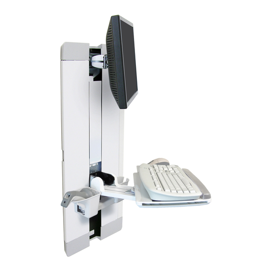
9" Vertical Lift with Slide-
out Keyboard Tray for Flat
Panel Monitor & Keyboard
OSHPD Mount or Standard Mount
Ergonomic Mounting Height Instructions . . . 2
Required Tools . . . . . . . . . . . . . . . . . 2
Components. . . . . . . . . . . . . . . . . . . 3
Wall Anchorage Requirements . . . . . . . . 4
OSHPD . . . . . . . . . . . . . . . . . . 5
Standard . . . . . . . . . . . . . . . . . 7
Monitor Attachment . . . . . . . . . . . . . . 9
Keyboard Attachment . . . . . . . . . . . . . 12
Dimensions . . . . . . . . . . . . . . . . . . . 16
Adjustment . . . . . . . . . . . . . . . . . . . 17
Cover Installation
and Cable Routing . . . . . . . . . . . . . . . 20
Trouble Shooting. . . . . . . . . . . . . . . . 22
User's Guide
USA 1-800-888-8458
Europe +31 20 312.29.39
1 of 22
Advertisement
Table of Contents

Related Manuals for Ergotron 9" Vertical Lift


Summary of Contents for Ergotron 9" Vertical Lift
-
Page 1: Table Of Contents
Adjustment ....17 Ergotron’s control, it is imperative that you consult with appropriate Cover Installation... - Page 2 Determine Ergonomic Mounting Height NO OSHPD REVIEW REQUIRED 888-25-003-02 rev.G • 05/07 2 of 22...
- Page 3 USA 1-800-888-8458 Europe +31 (0)33-45 45 600 www.ergotron.com Mounting Hole Template 198.755 53.023 22.543 7.825 2.088 .888 12.700 MOUNTING HEIGHT LINE: (OBTAINED BY SOLVING 4X Ø .500 CAUTION: Do Not PILOT HOLE EQUATION BELOW) MOUNTING HEIGHT EQUATION FOR STANDING remove cardboard APPLICATIONS: 67.50 (1715MM) - X = H...
-
Page 4: Components
In compliance with standards established for the anchorage and installation of instrument support sys- tems by the California Offi ce of Statewide Health Planning and Development (OSHPD), Ergotron, Inc. has obtained pre-approval for two 9" Vertical Lift mounting methods. These mounting methods are limited to... -
Page 5: Oshpd
The design of the wall studs is by the engineer of record. METHOD A OSHPD LIGHT GAUGE METAL STUD WALLS Construct metal stud wall with components shown below. Go to "step 1", page 2 to determine ergonomic mounting height, then continue with "step c", below. Mount lift chassis to wall as shown below, then proceed to "step 3", page 9. -
Page 6: Rev.g
3x4, #2 Hem Fir, Douglas Fir (four per blocking) or better wood blockings #12 wood screws with 2-1/2" penetration in the Ergotron mount- ing bracket. NOTE: Screws are to be 10d x 1-1/2" long placed in the nails (eight per vertical center of the 3x4 backing. -
Page 7: Standard
WARNING: The Wall Mounted 9" Vertical Lift must be securely attached to your wall. Because wall construction varies widely and your ultimate mounting method is out of Ergotron’s control, it is imperative that you consult with appropriate local engineering, architectural, or construction personnel to ensure that the 9" Vertical Lift is mounted properly to handle applied loads. - Page 8 STANDARD ANCHORAGE TO SHEETROCK WALL For applications where compliance to OSHPD is not required. If, after consulting with appropriate local engineering, architectural, or construction personnel it is determined that wall anchor hardware should be used, install as shown: Push anchor plate into hole. Pull loop back so plate opens fl...
- Page 9 (Video Electronics Standard Association) FDMI™ (Flat Display Mounting Interface) Standard Hole Mount ® WARNING: If your monitor uses a screw size which is different than those provided with your Ergotron mounting solution, use the screws provided with the monitor as those provided may damage your monitor. NO OSHPD REVIEW REQUIRED 888-25-003-02 rev.G •...
- Page 10 75 mm VESA FDMI™ ® Recessed Mount Flat Mount M4x10mm M4x20mm 100 mm VESA FDMI™ ® #8-32 x 3/16" Attach 75-100mm adaptor to monitor bracket. Attach 75-100mm adaptor/monitor bracket to monitor. Recessed Mount Flat Mount M4x10mm M4x20mm NO OSHPD REVIEW REQUIRED 888-25-003-02 rev.G •...
- Page 11 Mount monitor to lift WARNING: The monitor will not be securely attached to the 9" Vertical Lift until the Locking Pin passes through the tab on the Quick Release Bracket. Do not leave the monitor unsupported until you are certain the Locking Pin is in place. Lower monitor into position as shown.
- Page 12 Attach keyboard pivot #8-32 x 5/16" 20" - 22" (508-559mm) recommended Attach keyboard tray #8-32 x 5/16" NO OSHPD REVIEW REQUIRED 888-25-003-02 rev.G • 05/07 12 of 22...
- Page 13 VL Series Attachment Side Rear of Monitor View For VL Series to remain less than 4" (102 mm)* from the wall* Centerline of Four-Hole when in storage position, follow these guidelines: VESA FDMI Pattern 1. Monitor must not be more than 2-1/2" (63 mm) thick. ≤...
- Page 14 Mount keyboard to tray NO OSHPD REVIEW REQUIRED 888-25-003-02 rev.G • 05/07 14 of 22...
- Page 15 Keyboard mount (continued) Sterile Sterile Alcohol Prep Alcohol Prep Attach mouse pouch NO OSHPD REVIEW REQUIRED 888-25-003-02 rev.G • 05/07 15 of 22...
-
Page 16: Dimensions
Dimensions 4.4" (112 mm) 1.46" (37 mm) 11.79" 1" (299.6 mm) (25 mm) 29.38" 29.38" (746.3 mm) (746.3 mm) 16.5" (419 mm) 9" min. -12" max. 7.25" (230 mm - 300 mm) (184 mm) Front View Side View NO OSHPD REVIEW REQUIRED 888-25-003-02 rev.G •... - Page 17 After completion of installation steps, evaluate pivot function for your specifi c installation. Ergotron‛s pivot joints are fac- tory set to provide the proper pivot control and moving force for the majority of users. If excessive force is required to adjust your setup, or if your monitor or keyboard do not remain in the desired position, pivot adjustment may be required.
- Page 18 Tilt Keyboard Tray, with keyboard attached, through the entire 90° range. If Keyboard Tray pivot needs adjustment, tighten or loosen as required. Keyboard NOTE: adjust at each pivot point equally. Pivot 1/2" NO OSHPD REVIEW REQUIRED 888-25-003-02 rev.G • 05/07 18 of 22...
- Page 19 With all components loaded, move monitor and keyboard to highest and lowest positions. If adjustment is needed, tighten or loosen as required. Vertical Lift NO OSHPD REVIEW REQUIRED 888-25-003-02 rev.G • 05/07 19 of 22...
- Page 20 Attach covers and cable clips Remove monitor. Attach front cover. #8-32 x 3/8" Attach cable clips and side covers. NOTE: The four cable clips can be attached at any of the holes located along the top, bottom and sides of the lift chassis using the same screws that secure the side covers. Re-attach monitor after front and side covers are attached.
- Page 21 Reattach monitor. Slide-on keyboard covers. Route and organize cables with provided ties. NOTE: Cinch cables every 12" (305mm) NOTE: Leave enough slack in the cables for unrestricted movement. NO OSHPD REVIEW REQUIRED 888-25-003-02 rev.G • 05/07 21 of 22...
-
Page 22: Adjustment
Troubleshooting USA 1-800-888-8458 Monitor Pivot Europe +31 (0)33-45 45 600 www.ergotron.com Lift Tension Keyboard Pivot Weight Capacity The combined load capacity of the system (keyboard and monitor) ranges from 5-30 lbs. (2.3 - 13.6 kg). Symptom Probable Cause Solution Monitor and Keyboard drift Vertical Lift Tension needs adjust- upward or downward.
Need help?
Do you have a question about the 9" Vertical Lift and is the answer not in the manual?
Questions and answers