Table of Contents
Advertisement
Quick Links
-( £ It Ii
., "i;;
~
....
" ,
,,..,,;:~
4-
~
' ;
~
·"""41"· ......... '·'
_
b(,,~,
,~,
. , \ . . '"':.Ii'"
...
~~:
~
..,
o
q
~LI)"'"
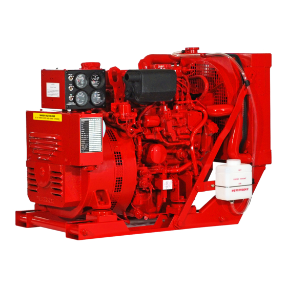
OPERATORS MANUAL
MARINE DIESEL
GENERATORS
8.0KW • 60Hz ......... 6.0KW • 50Hz BTDA
10.0KW • 60Hz ......... 7.5KW • 50Hz BTDA
11.5KW • 60Hz ........ ,9.2KW • 50Hz BTD
12.5KW • 60Hz ......... 9.4KW • 50Hz BTDB
12.6KW • 60Hz ...... 10.4KW • 50Hz BTD
15.0KW - 60Hz ..... 12.0KW • 50Hz BTDC
Single an
hase
PUBLICATION NO.44800
THIRD EDITION
JUNE 2008
WESTERBEKE CORPORATION' 150 JOHN HANCOCK ROAD
MYLES STANDISH INDf.lSTRIAL PARK' TAUNTON
MA
02780
WEBSITE: WWW.WESTERBEKE.COM
---.-.
.J,YJJ!.ttfIJ
Member NaJil>nal Marine Manu/aCIJITwAssociafiqn
Advertisement
Table of Contents
Troubleshooting

Related Manuals for Westerbeke 8.0KW - 60Hz


Summary of Contents for Westerbeke 8.0KW - 60Hz
- Page 1 12.6KW • 60Hz ..10.4KW • 50Hz BTD 15.0KW - 60Hz ..12.0KW • 50Hz BTDC Single an hase PUBLICATION NO.44800 THIRD EDITION JUNE 2008 WESTERBEKE CORPORATION' 150 JOHN HANCOCK ROAD MYLES STANDISH INDf.lSTRIAL PARK' TAUNTON 02780 ---.-. WEBSITE: WWW.WESTERBEKE.COM .J,YJJ!.ttfIJ Member NaJil>nal Marine Manu/aCIJITwAssociafiqn...
- Page 2 Shut down the unit and do not restart until It has been inspected and repaired. This WARNING DECAL is provided by WESTERBEKE and should be fixed to bulkhead near your engine Dr generator. WfSTERBEKE also recommends installing CARBON MONOXIDE DETECTORS in the living/sleeping quarters of your vessel.
- Page 3 SAFETY INSTRUCTIONS PREVENT BURNS - FIRE INTRODUCTION Read this safety manual carefully. Most accidents are WARNING: caused by failure to follow fundamental rules and precau- Fire can cause injury death! tions. Know when dangerous conditions exist and take the necessary precautions to protect yourself, your personnel, •...
- Page 4 SAFETY INSTRUCTIONS TOXIC EXHAUST GASES ACCIDENTAL STARTING WARNING: Accidental starting can cause Injury WARNING: carbon monoxide (CO) is deadly gas! death! • Ensure that the exhaust system is adequate to expel gases • Disconnect the battery cables before servicing the engine! discharged from the engine.
- Page 5 SAFETY INSTRUCTIONS ABYC, NFPA AND USCG PUBLICATIONS FOR • Do not wear loose clothing or jewelry when servicing equipment; tie back long hair and avoid wearing loose INSTALLING DIESEL ENGINES jackets, shirts, sleeves, rings, necklaces or bracelets that Read the following ABYC, NFPA and USCG publications could be caught in moving parts.
- Page 6 A detailed 40 page Marine Installation Manual covering gaSOline and diesel, engines and generators, is available from Jour WESTERBEKE dealer. /w-/WESTERBEKE En9ines Generators &...
-
Page 7: Table Of Contents
TABLE OF CONTENTS Glow Plugs ............24 Parts Identification ..........Generator Wiring Diagram ......... 25 Introduction ............Generator Wiring Schematic ......Warranty Procedures ........3 Generator Wiring Diagram Serial Number Location ....... .4 Diesel Fuel,. Engine Oil and Coolant....(with Electronic Governng) ...... -
Page 8: Parts Identification
PARTS IDENTIFICATION GENERATOR EMERGENCY STOP SWITCH LEFT SIDE CONNECTION TO BREAK OIL FI to.PlATE '--"~-I----+---EXHAUST ELBOW SOLENOID STARTER MOTOR REAR FRONT OIL PAN MANIFOLD PRESSURE CAP .FILL PREHEAT 'FILL RIGHT SIDE THERMOSTAT ASSEMBLY AIR INTAKE SILENCER & FILTER _---INJECTION PUMP ENGINE BLOCK DRAIN PLUG 20 AMP CIRCUIT... -
Page 9: Introduction
OF THE FURNISHING OR USE OF SUCH SOFTWARE. provided and a technical manual is available from your WESTERBEKE customers should also keep in mind the WESTERBEKE dealer. If you are planning to install this time span between printings of WESTERBEKE product equipment contact your WESTERBEKE dealer for software and the unavoidable existence of earlier WESTERBEKE'S installation manual. -
Page 10: Serial Number Location
INTRODUCTION SERIAL NUMBER LOCATION NOTE: A carbon monoxide warning decal has been provided by WESTERBEKE. Affix this decal in a visible position in the The engine and generator serial numbers and model numbers engine room. on~the are located on a decal generator housing. -
Page 11: Diesel Fuel,. Engine Oil And Coolant
Below 41°F (SOC) SAE 10W-30 or 15W-40 WESTERBEKE diesel engine. The purpose of this recovery tank is to allow for engine coolant expansion and contraction during engine operation, without the loss of coolant and without introducing into the cooling system. -
Page 12: Generator Control Panels
GENERATOR CONTROL PANELS DESCRIPTION OF SWITCHES EMERGENCY STOP: The EMERGENCY stop switch on the side of the control box, This manually controlled series ofWESTERBEKE marine is normally closed. When depressed, diesel generators is equipped with toggle switches on the will open the DC circuit to the control engine control panel and, optionally, at remote panels. -
Page 13: Preparations For Initial Start-Up
Foil w the procedures as presented for be switched OFF until the engine has come up to speed the conditions indic your WESTERBEKE generator and, In cold climates, starts to warm up. This precaution set will give reliable pem ance and long service life. -
Page 14: Starting/Stopping Procedure
CODl- This system is common to WESTERBEKE diesels. The start ing system during cranking. This raw water can enter the circuitry is designed so that the PREHEAT button must be engine's cylinders by way of the exhaust manifold once depressed fOf the time specified in the preheat chart. -
Page 15: Safety Shutdown Switches
STARTING/STOPPING PROCEDURE Coolant Temperature Switch STARTING UNDER COLD CONDITIONS A high coolant temperature switch is located on the thennostat Make sure the lubricating oil confonns with the ratings for housing. Nonnally closed, this switch, should the fresh water the prevailing temperature. Check the table in the ENGINE coolant's operating temperature reach approximately 210°F OIL section in this manuaL (99°C), will open and interrupt the DC voltage... -
Page 16: Generator Break·ln Procedure
GENERATOR BREAK-IN PROCEDURE DESCRIPTION CHECK THE FOLLOWING Although your engine has experienced a minimum of one Monitor the control panel gauges. hour of test operations at the factory to make sure accurate Check for leaks of fuel and engine oiL assembly procedures were followed and that the engine operated properly. -
Page 17: The Daily Operation
THE DAILY OPERATION START THE GENERATOR CHECK LIST (See STARTING PROCEDURES on previous pages). Follow this check list each day before starting your generator. Allow the engine to wann up for S to 10 minutes to reach an Record the hourmeter reading in your log (engine hours operating temperature of 140°... -
Page 18: Maintenance Schedule
MAINTENANCE SCHEDULE WARNING: NBvel attBmpt to pBrfDlm any SBIV/CS wh/Is ths sngins Is lunnlng. Wsal ths PfOPSI safBty squlpmsnt such as gogglss and glOVBS USB ths COfrsct tools fOf Bach Job. Dlsconnsct ths battsry tsrmlnals whsn sSIV/clng any of the snglns's DC slsctrlcal squ/pmsnt. NOTE: Many of the following maintenance jobs are simple but others are more difficult and may require... - Page 19 "Heat Exchanger Remove, have professionally cleaned and pressure tested. Air Intake Filter Clean every 100 operating hours. Replace as needed. Refer to page 17 of this manual. "WESTERBEKE recommends this service be performed by an authorized mechanic. Engines & Generators...
-
Page 20: Cooling System
When the engine is started cold, external coolant flow is pre- DESCRIPTION vented by the closed thermostat (although some coolant flow Westerbeke marine diesel engines are designed and equipped is bypassed around the thermostat to prevent the exhaust for fresh water cooling. Heat produced in the engine by com- manifold from overheating). -
Page 21: Thermostat
COOLING SYSTEM Refilling the Coolant Replacing the Thermostat After replacing the engine block drain plug, close the heat Remove the cap screws and disassemble the thermostat hous- exchanger's coolant petcock. Then pour clean, premixed ing as shown. When installing the new thermostat and gas- coolant into the manifold and when the coolant is visable in ket, apply a thin coat of sealant on both sides of the gasket the manifold, start the engine. -
Page 22: Changing The Raw Water Impeller
COOLING SYSTEM NOTE: Also follow the above procedure after having run hard CHANGING THE RAW WATER PUMP IMPELLER aground. Close the raw water intake valve. Remove the pump cover and gasket or a-ring with the aid of two screwdrivers or the engine temperature gauge ever shows a higher than pliers. -
Page 23: Air Intakelsilencer
COOLING SYSTEM Zinc Anode the zinc anodes need replacement. hold the hex boss into loos~ .. which the zinc anode is threaded with a wrench while A zinc anode, or pencil, is located in the raw water cooling ening the anode with another wrench. This prevents the hex circuit within the heat exchanger. -
Page 24: Fuel System
FUEL SYSTEM DIESEL FUEL FUEL FILTERS Use No.2 diesel fuel with a cetane rating of 45 or higher. Do The fuel injection pump and the fuel injectors are precisely not use kerosene or home heating fuel. manufactured and they must receive clean diesel fuel, free from water and dirt. -
Page 25: Engine Lubricating Oil
ENGINE LUBRICATING OIL LUBRICATION DIAGRAM 2. Replacing the Oil Filter. When removing the used oil fil- ter, you may find it helpful and cleaner to punch a hole in the upper and lower portion of the old filter to drain the oil from it into a container before removing it. -
Page 26: Oil Pressure
OIL PRESSURE DESCRIPTION TESTING OIL PRESSURE To test the oil pressure, remove the oil pressure sender, then The lubricating system is a pressure feeding system using install a mechanical oil pressure gauge in it's place. After an oil pump. The engine oil is drawn from the oil sump by warming up the engine, set the engine speed at 1800 rpm the oil pump, which drives the oil, under pressure, through and read the oil pressure gauge. -
Page 27: Remote Oil Filter
Contact your WESTERBEKE dealer for more information. engine room bulkhead. NOTE: Westerbeke is not responsible for engine failure due to NOTE: Refer to ENGINE OIL CHANGE in this tn£IJlualfor incorrect installation of the Remote Oil Filter. -
Page 28: Dc Electrical System
DC ELECTRICAL SYSTEM ALTERNATOR 1. Start the engine. 2. After the engine has for a few minutes, measure the The charging system consists of a belt driven alternator starting battery voltage at the battery terminals using a with a voltage regulator, an engine DC wiring haI)1ess, a multi meter set on DC volts. -
Page 29: Battery Care
DC ELECTRICAL SYSTEM Checking the Service Battery 7. Now check the voltage between the alternator output ter- and ground. If the circuit is good, the voltage at minal (B+) Check the vo1tage of the service battery. This battery should the alternator will be the same the battery, or an isola- have a voltage between 13 and 14 volts when the engine is... -
Page 30: Glow Plugs
GLOW PLUGS Re-install the plugs in the engine and test them again. The DESCRIPTION plug::; should get very hot (at the terminal end) within 7 to 15 The glow plugs are wired through the preheat solenoid. seconds. If the plugs don't heat up quickly, check for a short When PREHEAT is pressed at the control panel this solenoid circuit. -
Page 31: Generator Wiring Diagram
GENERATOR WIRING DIAGRAM #44735 -!---~ IU R It/I PRE HEAT BATTERY SWI TCH ..J?".;:t.--· all PRESSURE SI! ICH 12-24 VDC NOTE: An on-off switch should be Installed in this circuit disconnect the starter from the battery in an emergency and when leaving the boat Twelve volt engine starters typically draw 200 to 300... -
Page 32: Generator Wiring Schematic
GENERATOR WIRING SCHEMATIC #44735 6ATHR1' ;2-2.4VDC -,.-- GLOWPLUGS EMERGENcY STOP PREHEA I SWI TeH ISOLENOID! '1 TERNATOR KI-STARf Kl·RUN __________ ~r~a,~,', ~---r----------~3~a r8~1 ~-------.----~ ____ WATER j(MP eXN. TEMP OIL PRESS. $W! reH SWI TCH SW TCH fUE:.. PUMp STOP K2·R~N RELAY Isol... -
Page 33: Generator Wiring Diagram (With Electronic Governng)
GENERATOR WIRING DIAGRAM #044927 (OPTIONAL ELECTRONIC GOVERNING) ALTERNATOR -'lOA 24VDC AL TERNATOR 50A-12V WATER TEMPERATURE I I ' V 10 llllQil GLOW ..---=",-fOR [XC , 114 BRN PLUGS ORN~~ OMt (lLOW f'lU(l PER CYUt/DER 1110 ORG .-------------------------+-------+--------------------+~--~ IIt4 VIO 1j14 1112 y[lfREC ~/'"''''''''''... -
Page 34: Generator Wiring Schematic (With Electronic Schematic)
GENERATOR WIRING SCHEMATIC #044927 (OPTIONAL ELECTRONIC GOVERNING) r .., BATTERY SWITC~ C I R(;U I T STARiER BREAKER ~r~~~ --------O_--~~~--~ ____ r - - -__ GI.OWPlUGS r .., EMERGENCY STOP PREH[AT SWlfCH ISOl['O'~ TER~ATOR fill-START 1(2-RUIt __________ -, ____ ~,~.~,.~,----------~--~----------~3oy' ~.1~ wAT£lr T£kP. -
Page 35: Remote Instrument Panel
REAR VIEW #14 REO # 14 RED #16 YELIRED EXTENSION WIRING IS AVAILABLE P. N. 44336 FROM YOUR WESTERBEKE DEALER 15 FT EXTENSION - #044347 30 FT EXTENSION - #044799 CONNECTOR FOR TWO REMOTE PANELS - #046116 Engines & Generators... -
Page 36: Engine Troubleshooting (Chart)
ENGINE TROUBLESHOOTING Note: The engine's electrical system is protected by a 20 amp The following troubleshooting table describes certain manual reset circuit breaker located on a bracket at rear problems relating to engine service, the probable causes of of the engine. these problems, and the recommendations to overcome these problems. - Page 37 ENGINE TROUBLESHOOTING Probable Cause Verification/Remedy Problem Raw water not circulating. Raw water pump failure. Check impeller - replace. Generator engine overheats/shuts down. Coolant not circulating. 2. Obstruction at raw water intake or raw water filter. 2a. Thermostat - remove and test in hot water. Replace thermostat.
-
Page 38: Control Panel Troubleshooting
CONTROL PANEL TROUBLESHOOTING MANUAL STARTER DISCONNECT (TOGGLE SWITCHES) NOTE: The engine control system is protected a 20 amp manual reset circuit breaker located on the engine as close as possible to the power source. Problem Probable Cause Verification/Remedy Check switches and/or battery connections. PREHEAT depressed, no panel indications Oil Pressure switch. -
Page 39: Engine Adjustments
ENGINE ADJUSTMENTS DRIVE BELT ADJUSTMENT ELECTRONIC GOVERNOR (OPTIONAL) Proper inspection, service and maintenance of the drive belts Electronic Governor regulates the engine speed by is important for the efficient operation of your engine (see sensing the engine's RPM with a magnetic pick-up at the under flywheel. -
Page 40: Valve Clearance
ENGINE ADJUSTMENTS NOTE: WESTERBEKE recommends that the following engine adjust- ments be performed by a competent engine mechanic. The information below is provided to assist the mechanic. VALVE CLEARANCE ADJUSTMENT (b) With No.1 piston at top dead center on the compression stroke, the rocker arms will not be moved when the Make the following adjustments when the engine is cold. -
Page 41: Testing Engine Compression
ENGINE ADJUSTMENTS NOTE: WESTERBEKE recommends the following engine adjust- that ments be peiformed by a competent engine mechanic. The tnformation below is provided to assist the mechanic. FUEL INJECTORS TESTING ENGINE COMPRESSION Make certain the oil level (dipstick) is at the correct level and In case of severe vibrations and detonation noise, have the intake filter is clean. -
Page 42: Generator Information
Carbon Monoxide Detector the generating plant and the appliances supplies. If an AC WESTERBEKE recommends mounting a carbon voltmeter or ampmeter is not installed to monitor voltage and monoxide detector in the vessels living quarters. Carbon load, check it with a portable meter and amprobe. -
Page 43: Bt Generator
BT GENERATOR A circuit breaker is installed on all WESTERBEKE genera- This generator is a four-pole, brushless, self-excited generator tors.This circuit breaker will automatically disconnect gener- which requires only the driving force of the engine to pro- ator power in case of an electrical overload. The circuit duce AC output. -
Page 44: Internal Wiring (6 Stud)
BT GENERATOR I SINGLE PHASE [SIX STUD] r----[j-----l r----()-----1 I i ! ..RM1""t r-------------------, 60 Hz TERMINAL BOO! I~i) • ~-----------------~ • • _ ________ ". !JED GREEN GREEN BLACK BlACK BLACK BLACK + ...-'''''-.. -
Page 45: Generator Voltage Adjustment
GENERATOR VOLTAGE ADJUSTMENT NOTE: WESTERBEKE recommends that the following generator tests adjustments be peiformed by a quailified technician. Generator Frequency d. After the no-load hertz adjustment is made, the no-load voltage may need to be readjusted. most cases, if the 1. -
Page 46: Automatic Voltage Regulator
GENERATOR VOLTAGE ADJUSTMENT NOTE: WESTERBEKE recornmends that the following generator tests and adjustments be performed by a quailif{ed technician. FULL-LOAD VOLTAGE ADJUSTMENT NO-LOAD VOLTAGE ADJUSTMENT The voltage hertz connection bar that is used when changing Voltage adjustment is made with the generator regulation from 60Hz to 50Hz can also be used to increase or decrease being governed by the compound transformer. -
Page 47: Generator Internal Wiring
BT GENERATOR INTERNAL WIRING 3 PHASE TWELVE WIRE RECONNECTABLE r - - - - - - - - , EXCITER STATOR r------ DSTATOR r---- 1---- - - - - - -", 12". ----l1f---l--... -+1----.'11 I 10. -----~1~--~~1~------.'7 ROTOR FIELD : 8 ..EXCITER ...-------, rII-as:~1 -1.p1-... -
Page 48: Regulator Sensing 3 Phase
REGULATOR SENSING 3 PHASE WYE-OELTA CONFIGURATIONS NOTE: WESTERBEKE recommends that the followirzg generator tests and adjustments be performed by a qualified technician. DESCRIPTION PARALLEL WYE (STAR) The regulator is equipped with seven numbered tenilinals (0 to 6) and their related brass jumpers. The illustrations l-+_-"U"""... -
Page 49: Shore Power Transfer Switch
BT GENERATOR SINGLE PHASE Shore Power Connections (60 Hertz) OPTIONAL AUTOMATIC VOLTAGE REGULATOR (AVR) tor. .how. GaMrator NOtE: Dlegram c;onruactloft, 1wo ... BT 6 STUD MODELS ONLY w'r.1120~Volt$y.t.m. "G2 f":;' Forath ..-wire .yalem u •• dotted line' for the 01Ut hot '-; .. optional solid-state voltage regulator (board #34410) NL1 L2 /'..,..-.. -
Page 50: Generator Troubleshooting (Chart)
BT GENERATOR TROUBLESHOOTING CHART NOTE: WESTERBEKE recommends that the following generator tests and adjustments be peiformed by a qualified technician. 1. LOW VOLTAGE 60-100 VOLTS AC COMPONENT CHECKS: SELECTOR SWITCH (6 Stud Models) ROTOR COMPONENTS B2. EXCITER ROTOR DIODES 83. ROTOR FIELD WINDING B1. -
Page 51: Lay·up And Recommissioning
LAY-UP & RECOMMISSIONING Fuel System [Gasoline] General Top off your fuel tanks with unleaded gasoline of 89 octane Many owners rely on their boatyards to prepare their craft, or higher. A fuel conditioner such as STABIL gasoline including engines and generators, for lay-up during the off- season or for long periods of inactivity. - Page 52 Lay-up time provides a good opportunity to inspect your Lubrication.and cleaning of the starter drive pinion is WESTERBEKE engine to see if external items such as drive advisable, if access to the starter pennits its easy removal. belts or coolant hoses need replacement. Check your basic...
-
Page 53: Specifications (3 Cylinder Engine)
Full flow, paper element, spin-on type. Sump Capacity 3.9 U.S. (3.7 liters) (not including filter) Operating Oil Pressure 50 - 60 psi (3.5 - 4.2 kg/em,) (engine hot) Oil Grade API Specification CF or CG-4, SAE 30, lOW-3D, 15W-40 ,."""WESTERBEKE Engines Generators &... -
Page 54: 6.0Kw . 10.0N .5Kw
SPECIFICATIONS 8.0KW BTDA AC GENERATOR (Single Phase) Single Phase Brushless, four-pole, revolving field. Pre-lubricated, single-bearing design . • Reconnectable, single-phase transformer regulation (optional solid-state voltage regulation). Voltage 120 or 1201240 Volts - 60 Hertz 220 Volts - 50 Hertz. Voltage regulation: ±5% no load to full load. -
Page 55: 9.2Kw
SPECIFICATIONS 11.5KW BTD AC GENERATOR (Single Phase) AC GENERATOR (3 Phase) Single Phase Brushless, four pole, revolving field. Three Phase Brushless, six-pole, revolving field. Sealed Pre-lubricated, single bearing design. 11.5 KW - 60 Hertz lubricated, single-bearing design. 12 Lead Reconnectable. single phase transformer 9.2 KW - 50 HerlZ reconnectable for low voltage WYE, high regulation (optional solid state voltage... -
Page 56: Specifications (4 Cylinder Engine)
SPECIFICATIONS 12.5KW BTOB AND 15.0KW BTOC GENERAL FUEL SYSTEM Engine Type Diesel, four-cycle, four-cylinder, fresh water- General Open flow, self priming. cooled, vertical in-line overhead valve No.2 diesel oil (cetane rating of 45 or higher). Fuel mechanism. Fuel Injection Pump In-line plunger type (BOSCH). -
Page 57: 9.4Kw· 15.0/12.0Kw
SPECIFICATIONS 12.5KW BTOB AC GENERATOR (Single Phase) AC GENERATOR (3 Phase) Single Phase Brushless, four pole, revolving field. Three Phase Brushless, Six-pole, revolving field. Sealed Pre-lubricated, single bearing design. 12.5KW - SO Hertz lubricated, single-bearing deSign. 12 Lead Reconnectable, single phase transformer 9.3KW·... -
Page 58: Engine Torque Specifications
ENGINE TORQUE SPECIFICATIONS MAJOR BOLTS AND NUTS TORQUE Clamp Width Bolt or Nut Diameter Pitch across flats length kg -m Alternator Bracket 3.8-5.3 27-38 36.6 Back Plate 3.3-4.8 24-35 32.5 27±72 Connecting Rod Cap 3.55±0.25 34.8±2.5 Coolant Pump 1.6±2.4 12-17 17.2 12-17 Coolant Pump Pulley... -
Page 59: Standard Hardware
STANDARD HARDWARE BOLT HEAD MARKINGS numbers identify their strength with Metric bolt class bolts by 10.9 the Bolt strength classes embossed on the head of each bolt. strongest. (inch) Customary bolls are identifed by markings two to grade eight (strongest). The marks correspond to two marks less than the actual grade, Le.;... -
Page 60: Metric Conversion Data
STANDARD AND METRIC CONVERSION DATA LENGTH-DISTANCE Inches (1n) x 25.4::: Millimeters (mm) x .0394 :: Inches Feet (tt) x .305 ::: Meters (m) x 3.281 = Feet Miles x 1.609 ::: Kilometers (km) x .0621 Miles DISTANCE EQUIVALENTS 1 Degree of Latitude:: 60 Nm 111.120 km 1 Minute of Latitude 1 Nm 1.852 km VOLUME... -
Page 61: Raw Water Discharge Hose
The hose can be secured a plastic wire tie as illustrated. WESTERBEKE CORPORATION • 150JOHN HANCOCK ROAD MYLES STANDISH INDUSTRIAL PARK. TAUNTON MA 02780 WEBSITE: WWWWESTERBEKECOM... -
Page 62: Power Take Off System
AC KIT #034786 for 12 stud BT units. output or to operate the power takeoff. KIT #037134 for 6 stud BT units. Contact your WESTERBEKE DEALER for additional information. REMOVE COVER STUDS AND HARDWARE HOLD ACCESSORY TO THE... -
Page 63: Suggested Spare Parts
SUGGESTED SPARE PARTS WESTERBEKE MARINE DIESEL GENERATORS CONTACT YOUR WESTERBEKE DEALER FOR SUGGESTIONS AND ADDITIONAL INFORMATION WATER PUMP IMPELLER KIT HARDWARE KIT DRIVE BELTS WESTERBEKE RECOMMENDS CARRYING ENOUGH SPARE ENGINE OIL (YOUR BRAND) FOR AN OIL CHANGE (5 DTS.) AND A GALLON OF PREMIXED COOLANT. - Page 64 'WESTERBEKE Engines & Generators 1035WMDWc:yOO REVISED JUNE 2008...
Need help?
Do you have a question about the 8.0KW - 60Hz and is the answer not in the manual?
Questions and answers